Final Project: CompuArm Manager
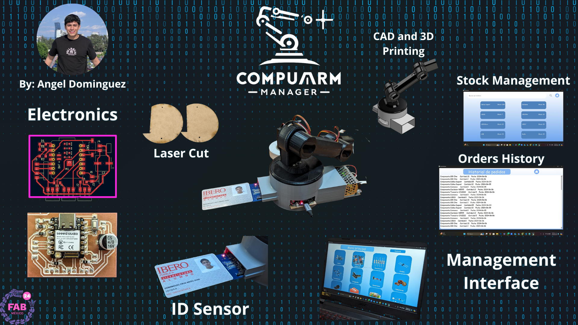
The idea of my final project is to make a system of stepper motors or servomotors that control a light or laser that points to the objects you are looking for. This idea comes from the necessity of knowing what are and where are the components we have available in our teacher's office.
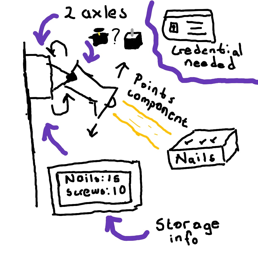
The system will consist of a computer with an interface that will let the students choose which components they want and send this infromation to our teacher and a motorized arm that moves the light or laser according to the coordinates of the desired object. The user will be able to select the object they are looking for from a list of available components on a screen. The system will then highlight the object with the light or laser, making it easier for the user to locate it.
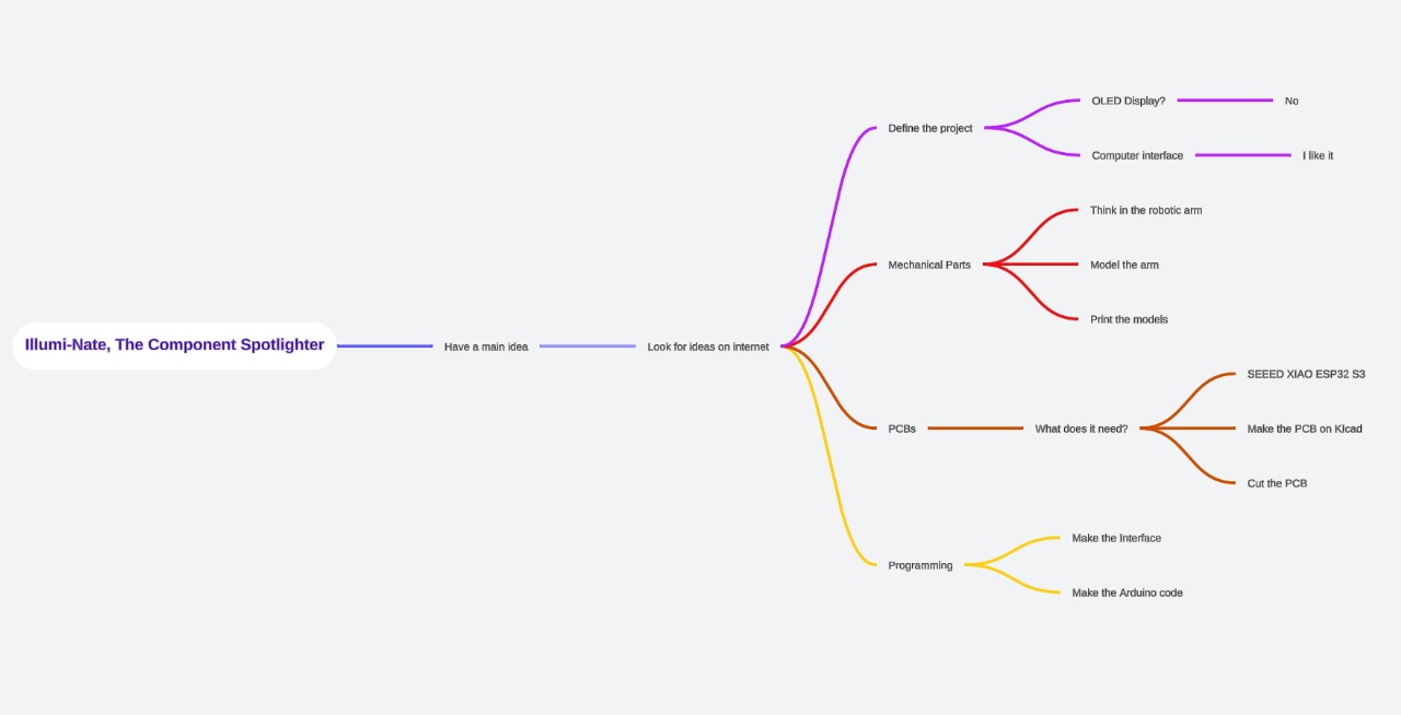
After some weeks of thinking in my final project, I changed some ideas from my first sketch. I decided to change the OLED display to an interface, I decided tu use servomotors (due to my experience using them) and I changed the lantern to a laser.
Similar Projects
There exist a lot of similar projects due to the nature of this project. The first similar project I found was a camera tracking system that uses ARduino to control two steppers. This system uses Python and it calculates the distance of the obejct from the camera frame's center to adjust the motors. The link to this ptoject is this one.
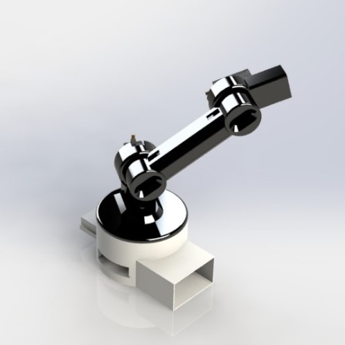
The project above was the most similar project to mine, but obviously I have to mention the robotic arms. We have a lot of types of robotic arms, and you can find on internet a lot of these ones that uses servomotors and steppers as they way to move. It is impossible to expose all the projects related to robotic arms on this section, but I will put some images of similar models to illustrate them.
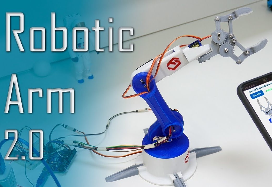
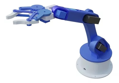
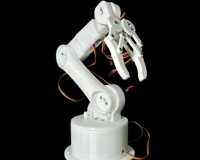
Like I said before, these were the most similar projects to mine, but none of these has the function of helping in a storage room or even pointing something. They were built for a completely other functions (most of them only for fun).
Table of Components
| Component | Number | Price | Obtained |
| Servomotors MG995 | 3 | 5 dls | Yes |
| Xiao ESP32S3 | 1 | 35 dls | Yes |
| Battery | 1 | 6 dls | Yes |
| Copper Plate | 1 | 1 dls | Yes |
| Milling Cutter | 1 | 1 dls | Yes |
| V Cutter | 1 | 2 dls | Yes |
| Laser | 1 | 4 dls | Yes |
| PLA Printing | - | 23 dls per kg | Yes |
Most of these materials were given to me by the university. The materials I bought were the laser and the Xiao ESP32S3.
| Sun | Mon | Tue | Wed | Thu | Fri | Sat |
|---|
3D Modeling
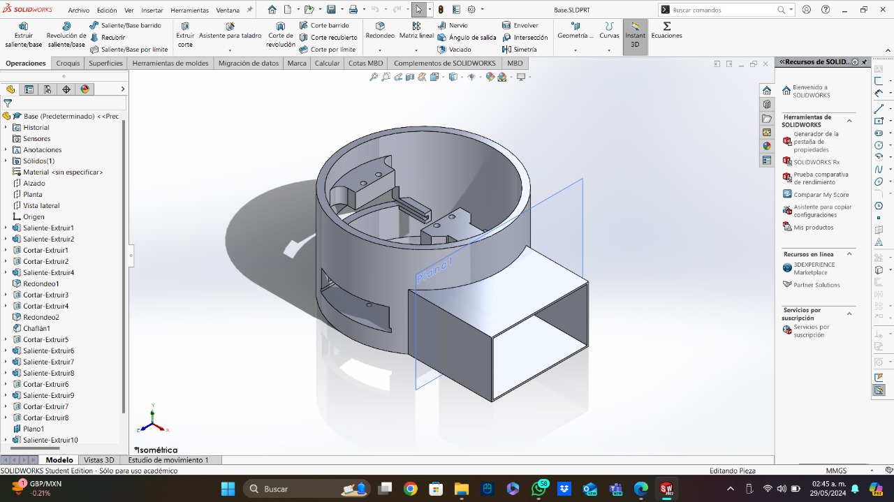
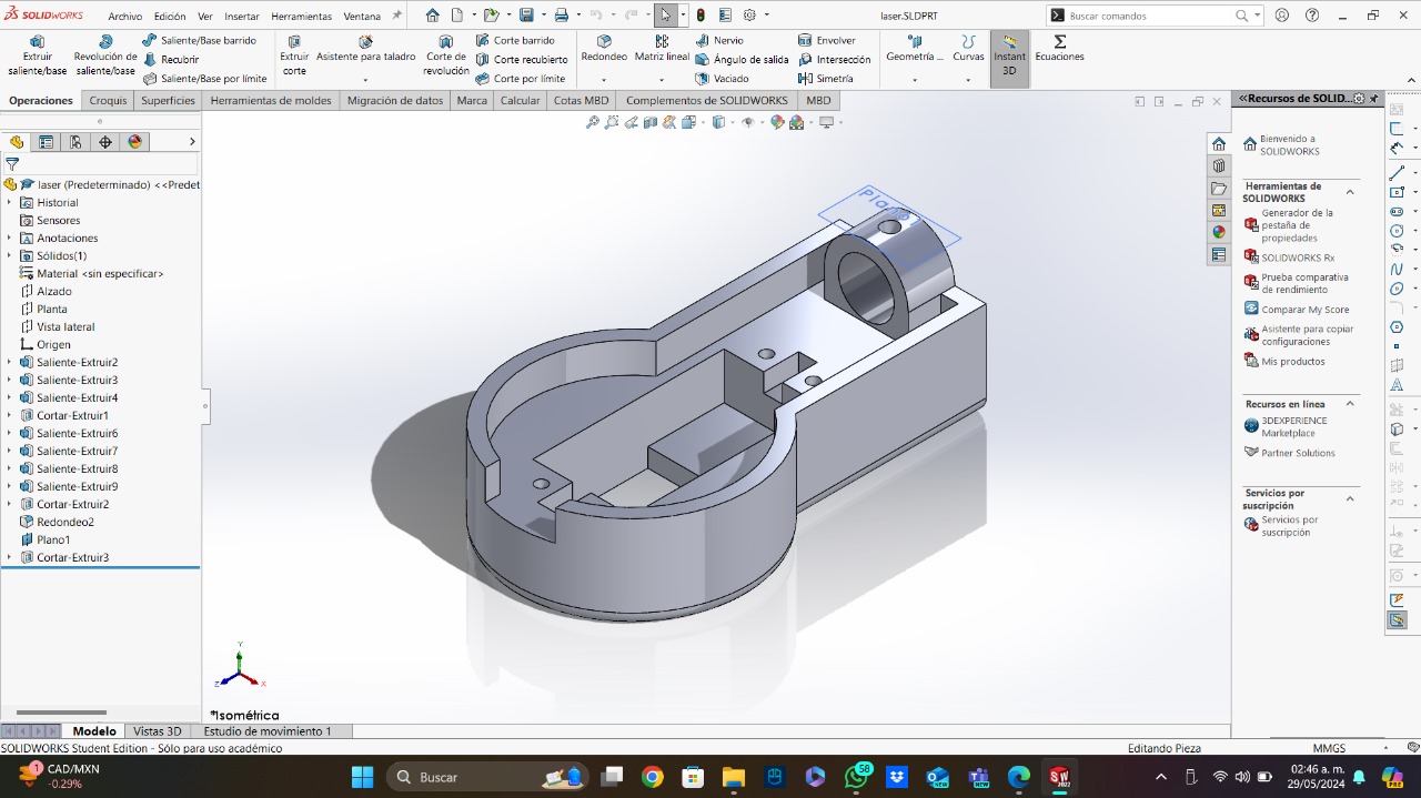
For this part, I designed four different pieces for my robotic arm. I will be using servomotors, so I decided to make a 3 axles robotic arm in order to have a bigger movement range. The first part is the base. I designed it thinking in all the components that are going to be inside the base, like the baterry, the PCB, the ID sensor, and other components. I also added the space for the servomotor.
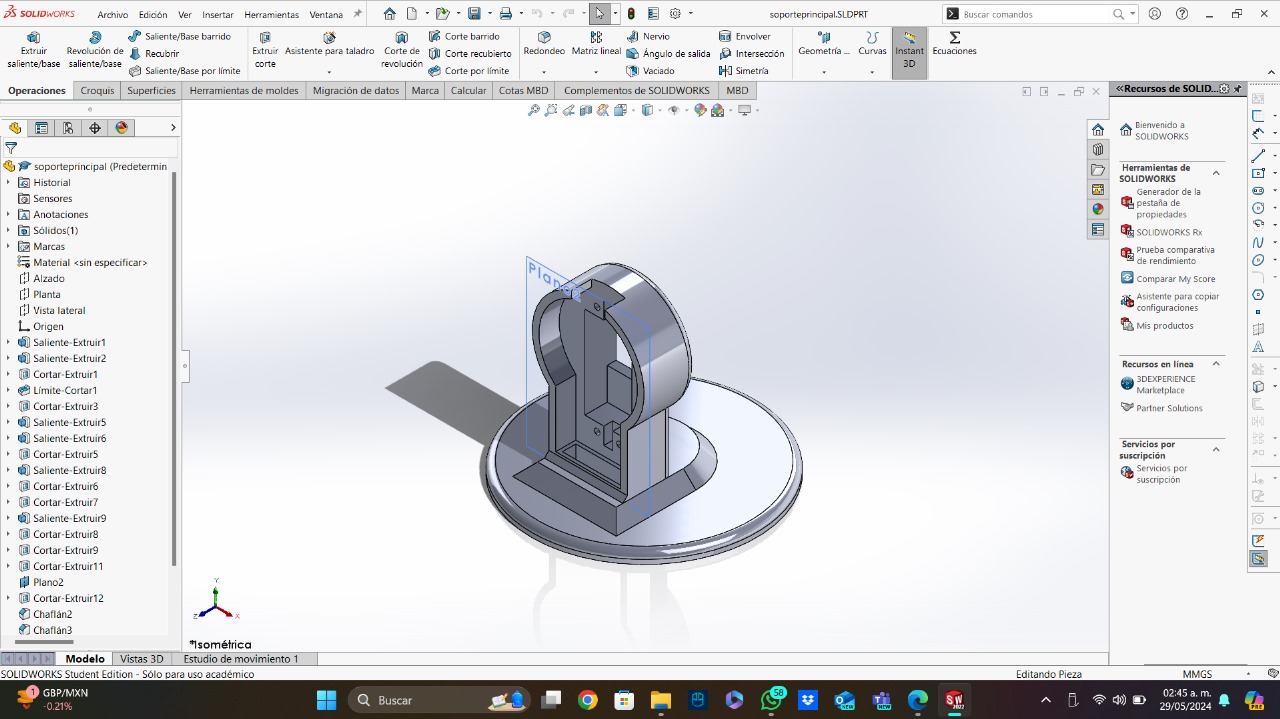
The next part was the arm support. This is the piece that will be connectet to the base. It has the slot for the servomotor and the slot for connecting the servomotor's base. It also has a little slot that connects with the base for the wires, in order to have all the wires inside the base.
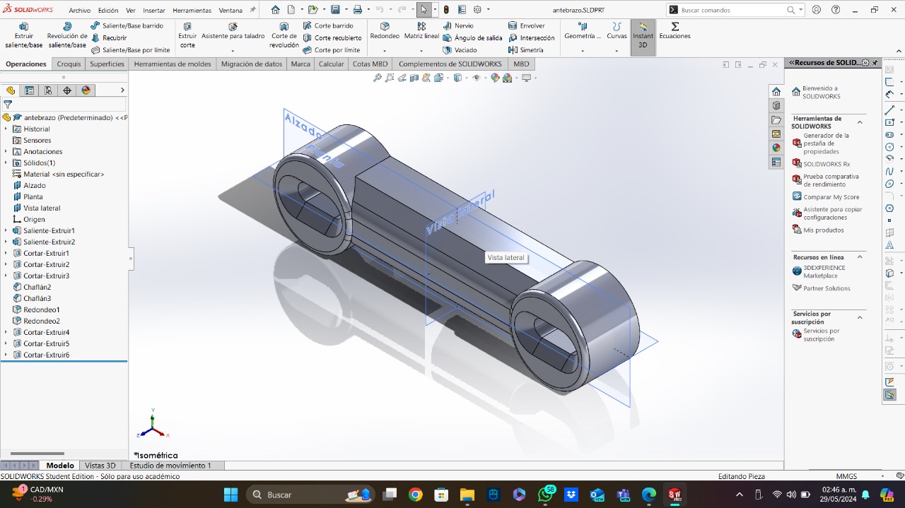
Connected to the support, we have the forearm (that's how I called it). This is a large piece of 3D printing that connects the laser part and the arm support. I decided to made it large in order to have hore height. It also have some slots for the wire management.
Finally, the laser part. This part has the slot for the last servomotor and the slot for the laser. It is a small piece that will give some extra movement range to the laser. I did it due to the servos restriction of only moving from 0° to 180°.
Here is an image of the assembly of all the pieces:
When I made sure the models work (checking them in the assembly), I started printing all the pieces. All the pieces worked in the first try, but I decided to make the forearm a little bit longer.
Electronics
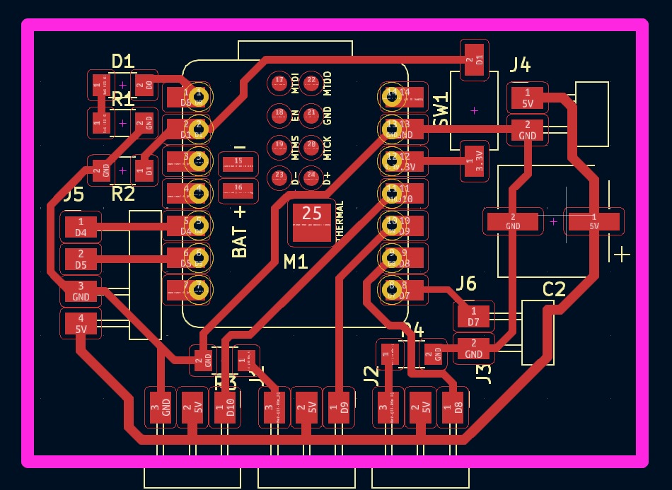
The electronic part of my project is very easy. I designed a PCB that will work using an ESP32-S3. The ESP32-S3 will control 3 different servomotors, the laser and the RFID sensor (which works using the I2C communication protocol). The pcb works with 2 different voltages, the first one is the one from de ESP32 (3.3V) and the other is the one from the power supply (5V). Due to the 2 voltages, I added 2 pins for the ground (to make it common) and for the voltage. I am using servos, so for avoiding voltage spikes, I added the biggest SMD capacitor I found (I need to avoid these spikes in order to delete the false signals). Finally, just for testing purposes, I added a LED and a button.
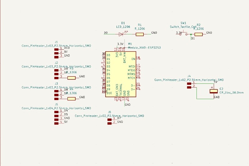
After I finished the schematic, I designed the real pcb. I did all the connections but I realized that some connections were kinda difficult, so I decided to add 2 resistors with a value of 0 Ohms. I decided to use a rectangle as the margin in order to simplify the pcb slot in the robotic arm base.
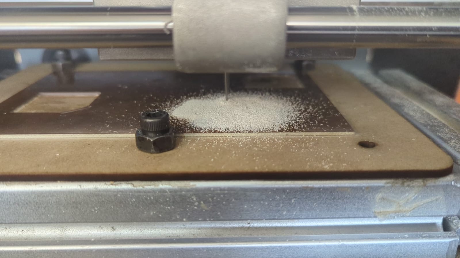
After I milled the pcb, I started the soldering process. To be honest, it took me some days to solder all the pcb, leaving the pins for the servomotos and the I2C communication.
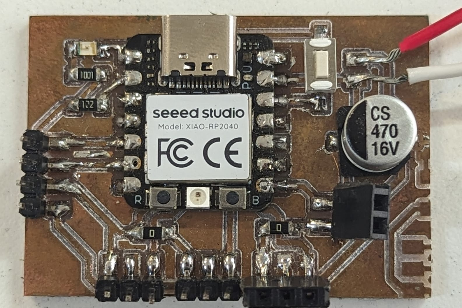
I did some testings trying to move the servos, but I couldn't move any of the servos. I tried using 4 different libraries and using ChatGPT, but some libraries just didn't work and the others marked some errors on the library. I tried a whole day, but I got beaten, so I decided to change the ESP32 t the RP2040. I checked the pinout of both microcontrollers and fortunately I didn't need to change the pcb. The RP2040 works with the common servo library of Arduino, so I unsoldered the ESP32, but in doing so, I tore off some paths, so I had to mill the pcb again.
I soldered all the pcb againg using the RP2040, and in this case, it worked really fast only moving the servos.
Interface
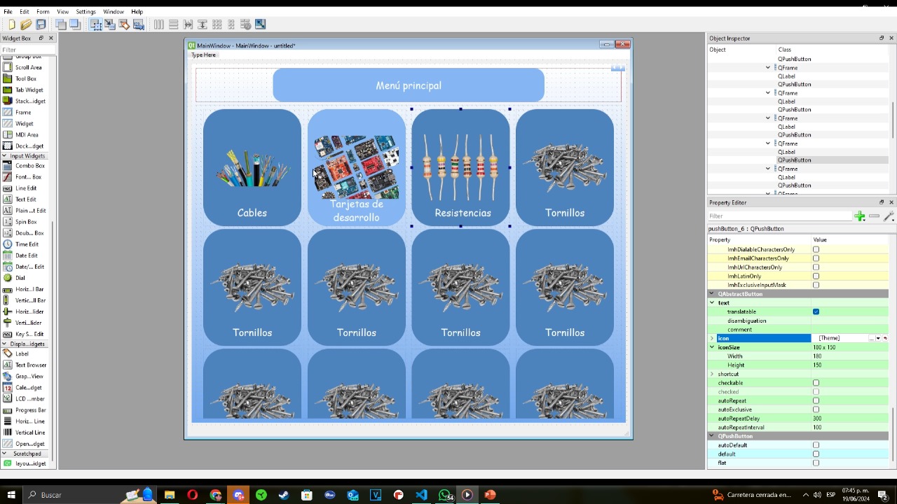
This part is kinda weird if you don't have any kwoledge about data bases and interfaces. First, I created the interface, this was very easy, first I changed the background color added a button with the image of the component and its name.
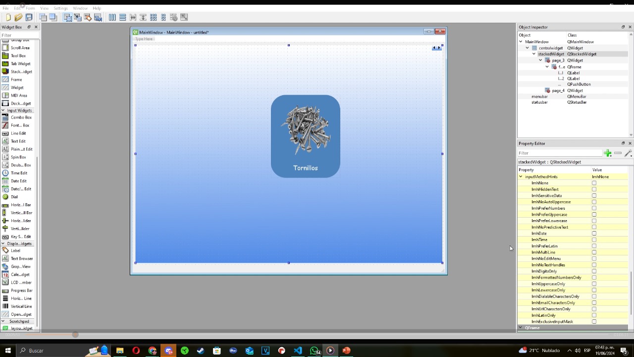
The second step for the interface is adding a grid label to dupliucate the first button in order to have all the components.
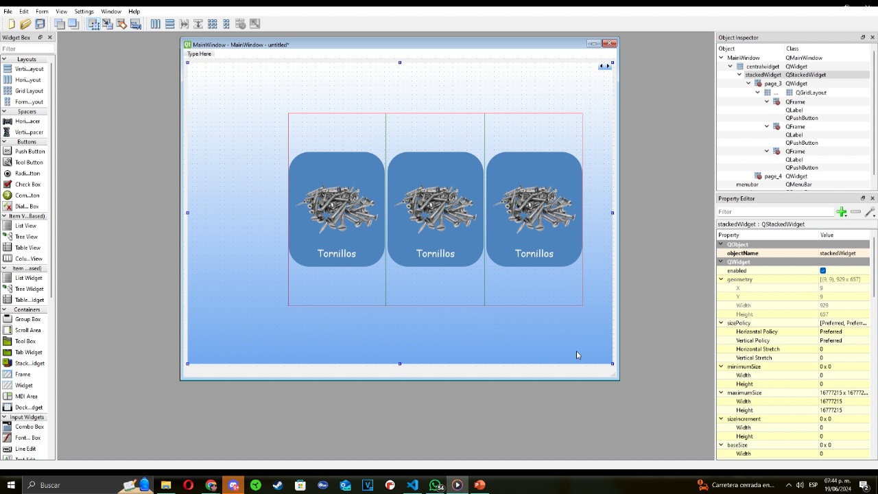
And finally, I changed all the buttons names and images and added the title using a text label alligned to the center of the main page.
This was the easy part, the next part is kinda complex if you don't have any idea of these topics. I needed some help from my system engineer friends. I basically created dynamic buttons that got created when you search the name or category of the object.
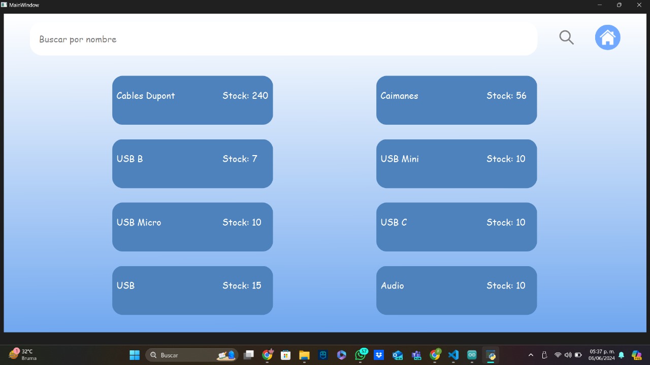
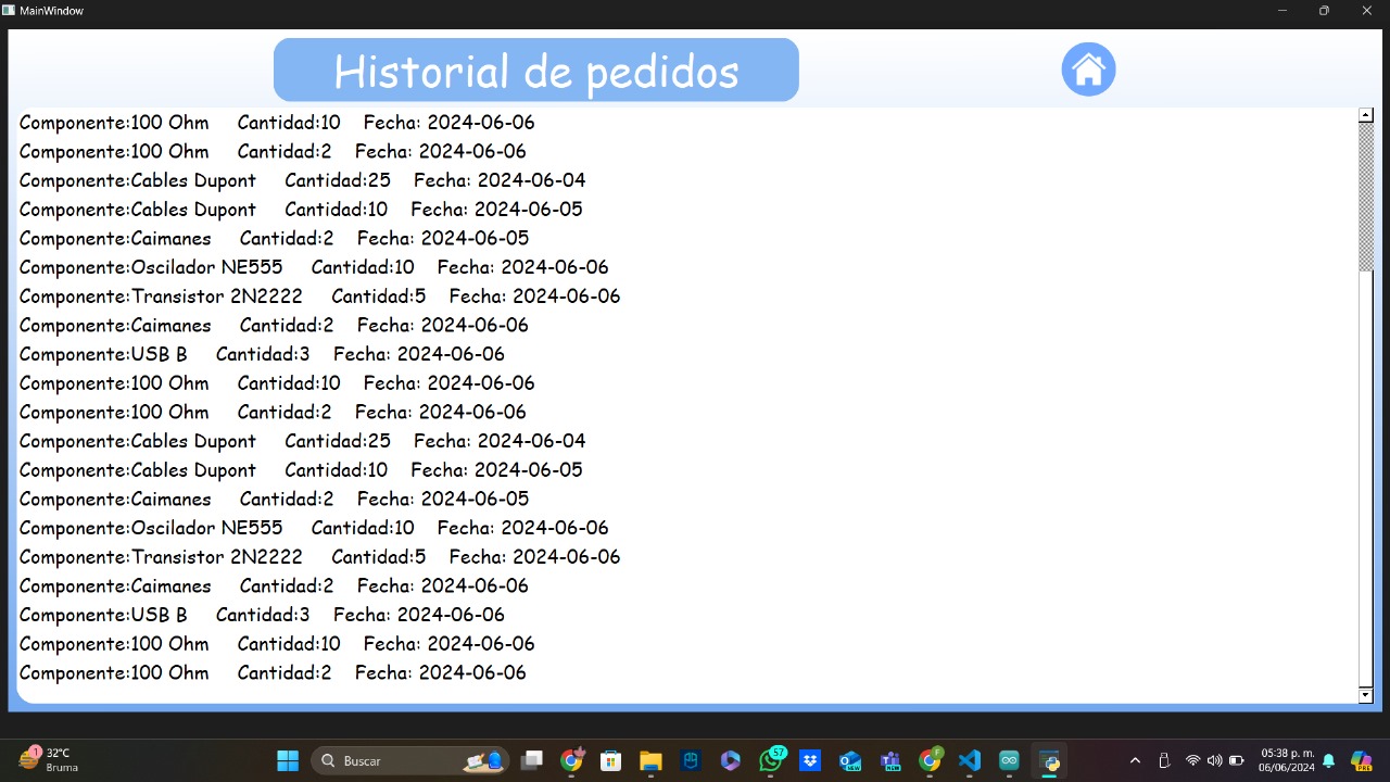
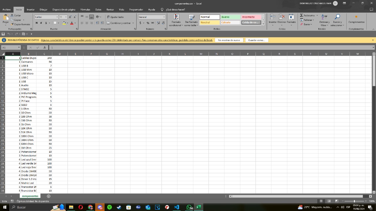
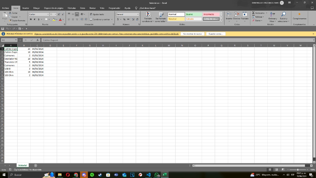
I also created two csv. The first one is used for manage the amount of components taken how many are left. The second one is used to create the interface history. Both of this are to the interface, and worked saving the data on a list and writing the csv.
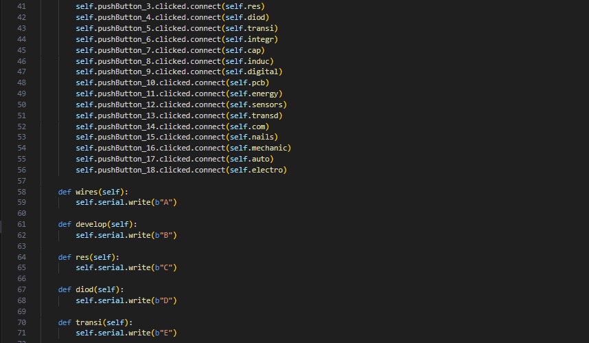
Finally, I creted all the functions needed for the communication between the microcontroller and the interface. These communications consists in buttons that send a different letter depending in which is pushed. The microcontroller receives each letter and depending in the letter, it moves the servos to a position.
Arduino
For this part, I am going to explain the code used in the microcontroller. This code is in charge of reading the RFID card, receiving the letter for the interface and moving the servos.
Arduino Code:
#include
#include
#include

Servo servo1;
Servo servo2;
Servo servo3;

const int servoPin1 = D10;
const int servoPin2 = D9;
const int servoPin3 = D8;
const int ledPin = D7;

#define SDA_PIN 4
#define SCL_PIN 5

Adafruit_PN532 nfc(SDA_PIN, SCL_PIN);

char comando = ' ';
bool tarjetaDetectada = false;
void setup() {
  Serial.begin(115200);
  while (!Serial) { ;
  }
  Serial.println("Iniciando...");

  servo1.attach(servoPin1);
  servo2.attach(servoPin2);
  servo3.attach(servoPin3);
  Serial.println("Servos conectados.");

  servo1.write(0);
  servo2.write(0);
  servo3.write(0);

  pinMode(ledPin, OUTPUT);
  Serial.println("LED configurado.");

  Wire.begin();
  Serial.println("Comunicación I2C iniciada.");

  nfc.begin();
  Serial.println("Iniciando PN532...");
  uint32_t versiondata = nfc.getFirmwareVersion();
  if (!versiondata) {
    Serial.println("No se encontró el PN53x. Check hardware connection.");
    while (1) { ;
    }
  }
  Serial.print("Firmware encontrado: ");
  Serial.print((versiondata>>24) & 0xFF, HEX);
  Serial.print('.');
  Serial.print((versiondata>>16) & 0xFF, HEX);
  Serial.print('.');
  Serial.print((versiondata>>8) & 0xFF, HEX);
  Serial.println((versiondata>>0) & 0xFF, HEX);

  Serial.println("PN532 encontrado!");
}
void loop() {
  if (Serial.available() > 0) {
    comando = Serial.read();
    Serial.print("Comando recibido: ");
    Serial.println(comando);
  }

  uint8_t success;
  uint8_t uid[] = {0, 0, 0, 0, 0, 0, 0}; // Buffer para almacenar el UID de la tarjeta
  uint8_t uidLength;
  nfc.SAMConfig();
  Serial.println("Esperando tarjeta...");
  success = nfc.readPassiveTargetID(PN532_MIFARE_ISO14443A, uid, &uidLength);

  if (success) {
    if (!tarjetaDetectada) {
      tarjetaDetectada = true;
      Serial.println("Tarjeta detectada!");
      Serial.print("UID: ");
      for (int i = 0; i < uidLength; i++) {
        Serial.print(" 0x");
        Serial.print(uid[i], HEX);
      }
      Serial.println();
    }

    if (comando != ' ') {
      ejecutarComando(comando);
      comando = ' '; // Resetear comando después de ejecutarlo
    }
  } else {
    if (tarjetaDetectada) {
      tarjetaDetectada = false;
      Serial.println("Tarjeta removida, esperando nueva tarjeta...");
    }
  }

  delay(500);
}
void ejecutarComando(char comando) {
  switch (comando) {
    case 'A':
      digitalWrite(ledPin, HIGH);
      moverServos(170, 60, 90);
      digitalWrite(ledPin, LOW);
      break;

    case 'B':
      digitalWrite(ledPin, HIGH);
      moverServos(45, 90, 135);
      digitalWrite(ledPin, LOW);
      break;

	...

	default:
      Serial.println("Comando desconocido");
      break;
  }
}
void moverServos(int angulo1, int angulo2, int angulo3) {
  servo1.write(angulo1);
  servo2.write(angulo2);
  servo3.write(angulo3);

  delay(2000);

  Serial.println("Regresando servos a 0 grados");
  servo1.write(0);
  servo2.write(0);
  servo3.write(0);
}
Testing
The testing part was kinda fast and easy. For the first test, I just move the servos to different positions using the RP2040. In this test, I realized that one servo was broken and caused a short circuit on the power supply. I changed this servo and then the arm started to work properly.
The next step was testing the RFID sensor. It took me a while to make it work, but after some research and some help of ChatGPT, I made it work. It is important to setup the sensor to the I2C mode, because the one I used, can be used with different types of communication protocols. Here is an image of how it works.
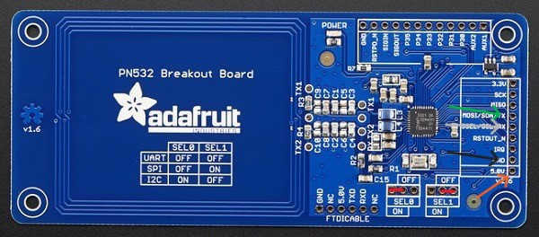
The image above, shows how the sensor needs to be connected. The red wires on the bottom part are for selecting the communication mode (in my case, I2C) and the other pins pointed by arrows are those needed for the I2C communication protocol.
Before I included the RFID sensor on my final project, I tested it using the PCB. Here is the code I used:
#include
#include

#define SDA_PIN 4
#define SCL_PIN 5

Adafruit_PN532 nfc(SDA_PIN, SCL_PIN);
void setup(void) {
  Serial.begin(115200);
  Serial.println("Hello!");

  nfc.begin();

  uint32_t versiondata = nfc.getFirmwareVersion();
  if (!versiondata) {
    Serial.print("Didn't find PN53x board");
    while (1); // Detener el programa si no se encuentra el sensor
  }

  Serial.print("Found chip PN5"); Serial.println((versiondata >> 24) & 0xFF, HEX);
  Serial.print("Firmware ver. "); Serial.print((versiondata >> 16) & 0xFF, DEC);
  Serial.print('.'); Serial.println((versiondata >> 8) & 0xFF, DEC);

  nfc.SAMConfig();

  Serial.println("Waiting for an NFC card ...");
}
void loop(void) {
  uint8_t success;
  uint8_t uid[] = { 0, 0, 0, 0, 0, 0, 0 }; // Buffer para guardar el UID
  uint8_t uidLength;                      // Tamaño del UID

  // Esperar a que se presente una tarjeta
  success = nfc.readPassiveTargetID(PN532_MIFARE_ISO14443A, uid, &uidLength);

  if (success) {
    Serial.println("Found an NFC card!");

    // Imprimir el UID de la tarjeta
    Serial.print("UID Length: ");Serial.print(uidLength, DEC);Serial.println(" bytes");
    Serial.print("UID Value: ");
    for (uint8_t i = 0; i < uidLength; i++) {
      Serial.print(" 0x");Serial.print(uid[i], HEX);
    }
    Serial.println("");

    // Esperar un momento para evitar lecturas repetidas
    delay(1000);
  }
}
This is a video of the working code:
After making the sensor work, I added all the pieces to the 3D models using jumpers for testing the protoype.
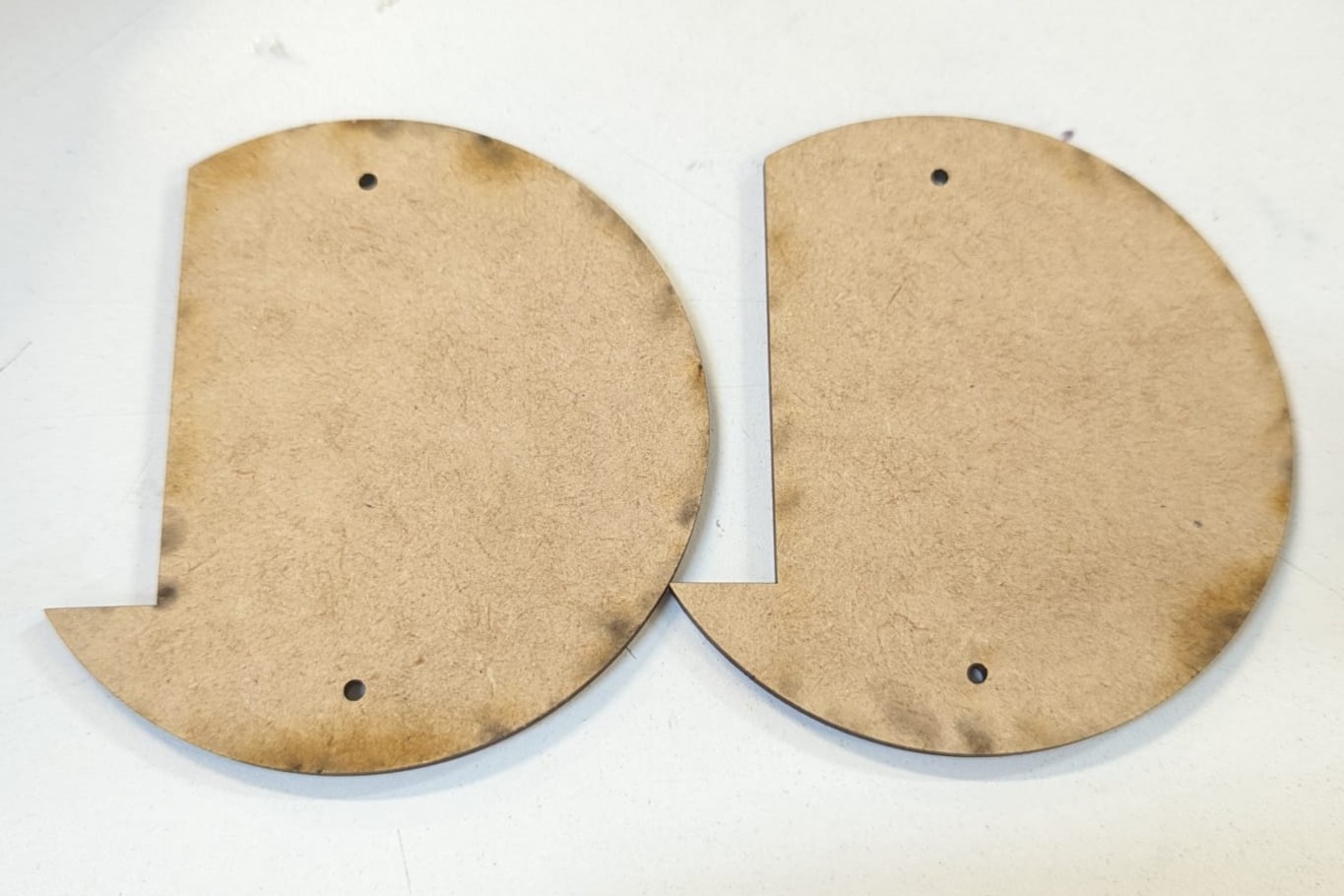
When I discovered the protoype works together, I added the mdf parts used for the bottom part of the base. I took the mdf directly from the bottom part of the model so it fitted exactly to the model.
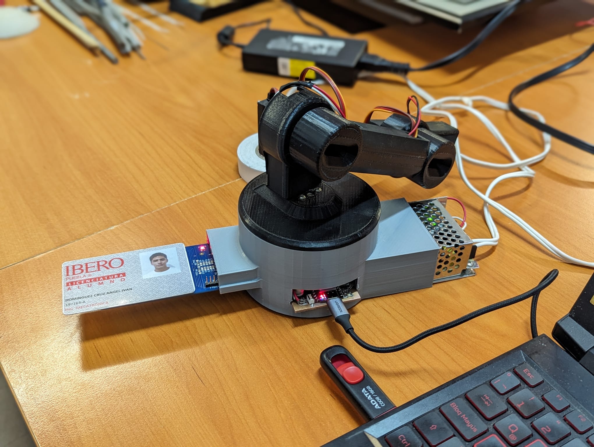
Finally, I added all the components in the model, finished the soldering process of all the wires and finished to connect all the components (servos, laser, power supply and RFID sensor). Here is a picture of the final project assembled.
Final Result
Here is a video of the final product working with the interface:
To download the files used for this project, you can click here.
CompuArm Manager by Angel Iván Domínguez Cruz is licensed under Creative Commons Attribution 4.0 International![]()
![]()