13. Networking and Communications
On this week I learned to communicate different microcontrollers using some protocols. In my case I used the I2C communication, the same one used for controlling the OLED display. To fully understand this week, you should check the week4 and the week8. To visit the group website, click here.
I2C
The I2C (Inter-Integrated Circuit) protocol is a synchronous, multi-master, multi-slave, packet-switched communication interface designed to allow multiple microcontrollers to communicate with each other or with various devices over a common bus. I2C uses two bidirectional lines, Serial Data Line (SDA) and Serial Clock Line (SCL), pulled up with resistors. Each device connected to the bus is software-addressable by a unique address and simple master/slave relationships can be established.
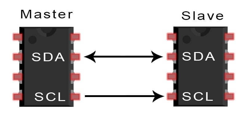
The connection process includes the master microcontroller initializing communication by sending a start condition, followed by the address of the slave device. The address is succeeded by a read/write bit that signals the desired operation. When a slave device is on the bus, it responds by pulling the data line low, indicating that the request has been received. It proceeds to send or receive data according to the operation that has been indicated. Subsequently, the communication ends after the master generates a stop condition. In this addressing method, many slave devices can be independently controlled by one bus. In this way, resources are saved and the wiring aspect is eased in complex systems.
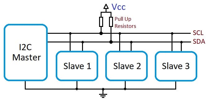
The I2C protocol supports different data transfer rates, from the standard speed of 100 kbps to a high-speed mode of 3.4 Mbps. It also includes features such as clock stretching, where a slower slave can keep the line low of the clock to delay the master until he is ready to board, and officiate. If two masters start transmission at the same time, the one sending the highest priority address (lowest numerical value) wins the bus.
PCB
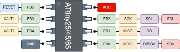
For this week, I designed a new PCB in order to connect the Quentorres, my PCB from the week8 and this new PCB. For this PCB, I used an Attiny45, a push-button and a lot of pins. The pins used for the PCB were the programming ones (MISO, MOSI, SCK, Reset, Vcc, and Ground) and two pairs of the I2C pins. Here's the pinout of the Attiny45:
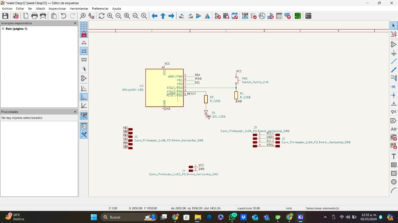
This is an image of the schematic of my PCB:
This is an image of the Kicad design of my PCB:
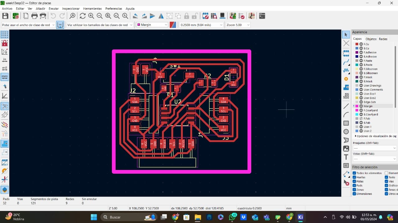
I need to specify that I made a big fail designing the PCB. When I made the schematic, I connected the ground pin of the LED to voltage, something that would have probably burned out the led. Fortunately, I realized this before soldering the components and didn't burn anything.
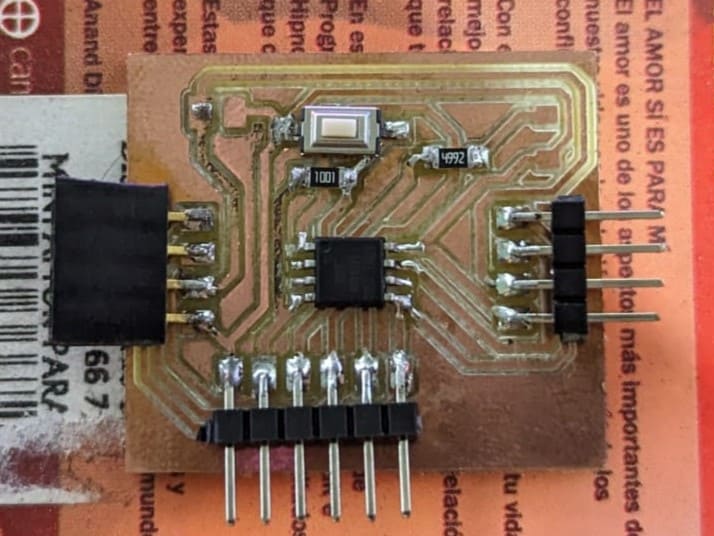
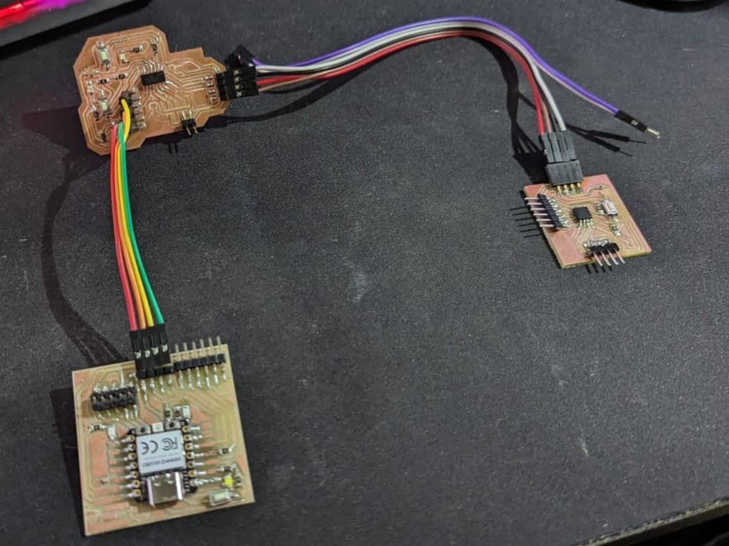
After the soldering proccess of the PCB, I also added some pins to my old PCBs in order to get enough I2C pins for the connections. The images below show the new PCB and the way I connected the 3 PCBs:
For programming the Attiny44 and the Attiny45, I used an Arduino NANO in order to use the Arduino IDE for the codes. I have a short tutorial of how to program the Attiny using the Arduino on my week8.
The Codes
I decided to use the PCB from week4 as the master and the week8 and the new one PCBs as the slaves. I decided to make something simple just to understand how the communication works. The master was in charge of printing in the Serial Monitor a button state, the Attiny44 was in charge of turning on a LED and the Attiny45 was in charge of sending the button signal. These are the codes:
XIAO RP2040 Code:
#include < Wire.h >

void setup() {
  Serial.begin(9600);
  Wire.begin();
}
void loop() {
  int estadoBoton = 0;

  // Solicitar el estado del botón al ATtiny45 en la dirección 3
  Wire.requestFrom(3, 1);
  if (Wire.available()) {
    estadoBoton = Wire.read();
  }

  // Envía el estado del botón al ATtiny44 en la dirección 2
  Wire.beginTransmission(2);
  Wire.write(estadoBoton);
  Wire.endTransmission();

  // Debugging por Serial
  Serial.print("Estado del botón: ");
  Serial.println(estadoBoton);

  delay(500);
}
You can copy the code right here:
Attiny44 Code:
#include < Wire.h >

#define led1 9

void setup() {
  pinMode(led1, OUTPUT);
  digitalWrite(led1, LOW);
  Wire.begin(2);
  Wire.onReceive(receiveEvent);
}
void loop() {
  delay(1000);
}

void receiveEvent(int howMany) {
  while (Wire.available()) {
    int estado = Wire.read();
    if (estado == HIGH) {
      digitalWrite(led1, HIGH);
    } else {
      digitalWrite(led1, LOW);
    }
  }
}
You can copy the code right here:
Attiny45 Code:
#include < Wire.h >

#define boton1 3  // Asegúrate de que este es el pin correcto para el botón
int estadoBoton = 0;

void setup() {
  pinMode(boton1, INPUT);
  Wire.begin(3);  // Configura como esclavo en dirección 3
  Wire.onRequest(requestEvent);  // Responde cuando el maestro solicite datos
}
void loop() {
  estadoBoton = digitalRead(boton1);  // Lee el estado del botón constantemente
}

void requestEvent() {
  Wire.write(estadoBoton);  // Envía el estado del botón al maestro
}
You can copy the code right here:
Here is the video of the all the PCBs and microcontrollers working together: