4. Electronics Production
On this week I worked on learning how to solder SMD components. Thanks to what I am studying (mechatronics engineering) this wasn't my first time soldering, so I didn't last a lot on thew soldering process.
Making the PCB Program
This week wasn't focused on designing the PCB, so the PCB I used for this week was designed by our main evaluator. You can find these files on the gruop task website, the link to the website is this one. For this week, I am going to use a cutting machine to bring the PCB model into real life. This machine uses a cutter tool to remove all the copper that isn't needed on the PCB paths. On the group website you can also watch the tolerances and cofigurations needed to use the cutting machine.
Now, I am going to explain how to create the file needed to use the cutting machine and create a physical PCB. To create this file, I used the MODS website because it has a program already made for the SRM-20 Mill (this is the cutting machine we have in Puebla). You can find the MODS website at our gruop website or at this link.
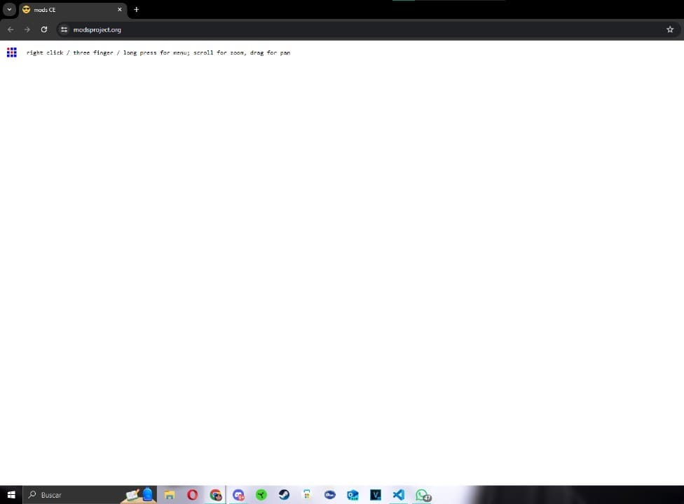
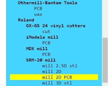
- The Website: After clicking the website link, you are going to find a white screen with no buttons. To get into the SRM-20 program, I right clicked the white screen and selected the "mill 2d PCB".
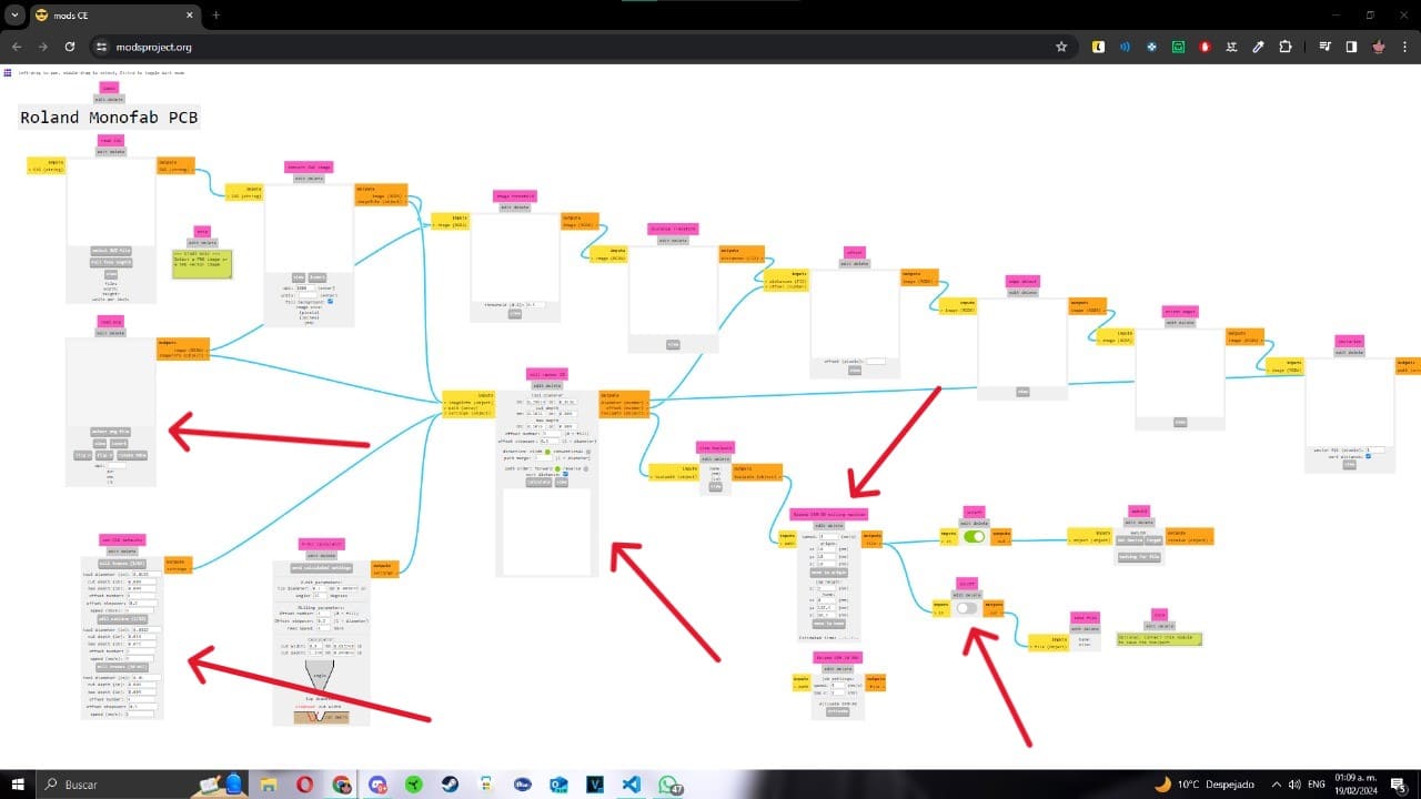
- The Program Screen: On this screen, you are going to watch a lot of many interconnected optiones. This screen looks kinda difficult to understand, but we are only going to use some of the options to create our PCB file. The options that we are going to use are marked with an arrow.
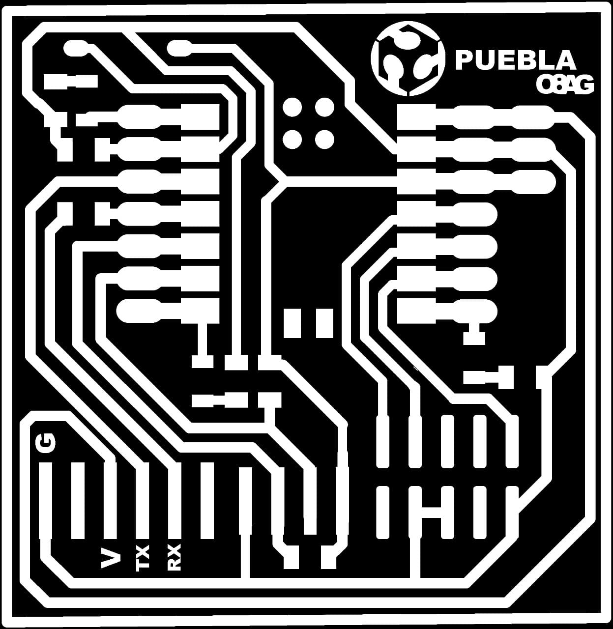
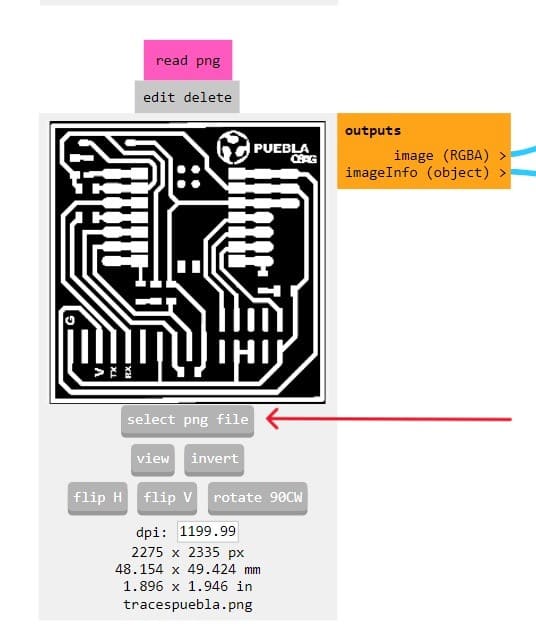
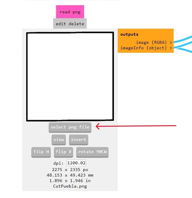
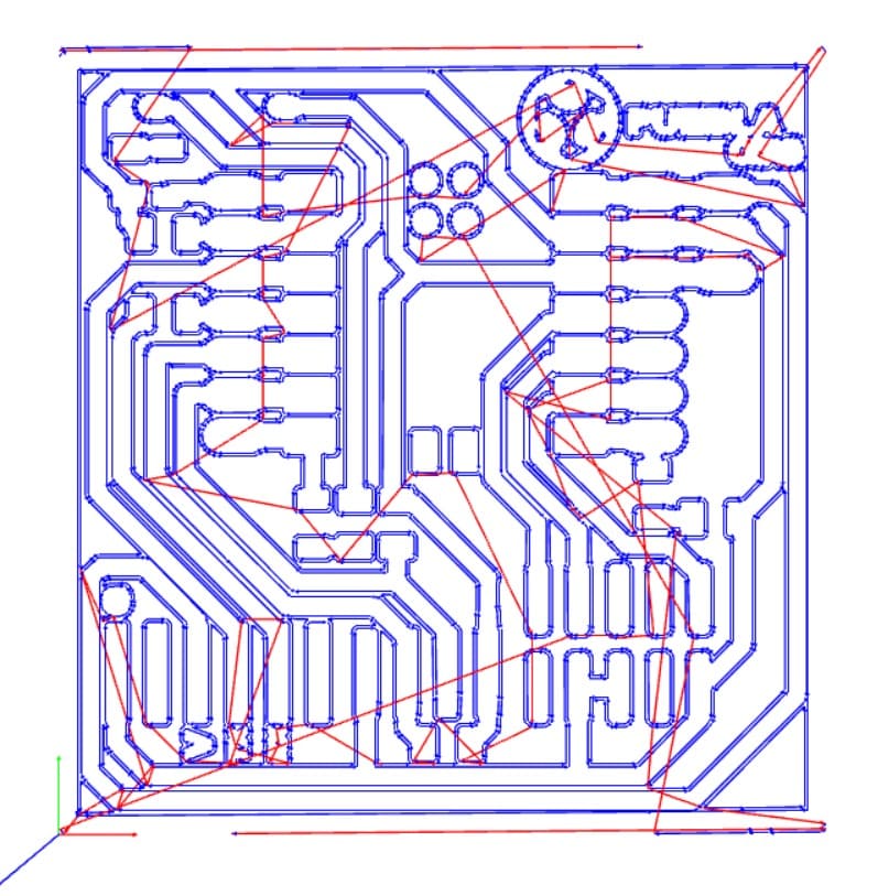
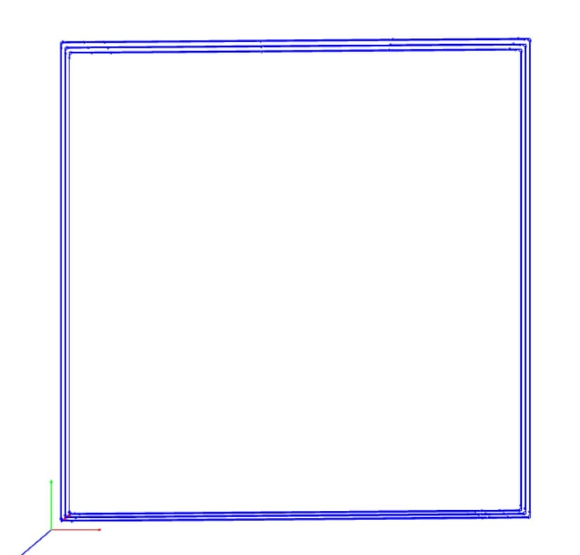
- The Images: In this week, we use two PNG images to create our PCB. The first image is the PCB paths and the second one is just the frame of this paths. These images can be found on the group website and are these ones:
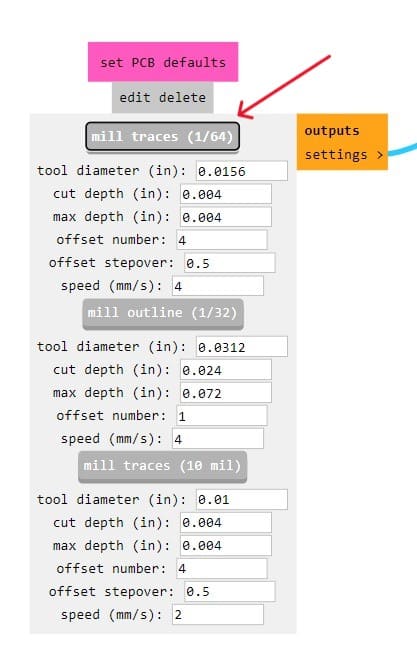
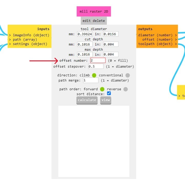
- PCB Paths: For the first image, I uploaded the paths image, then I used the "mill traces (1/64)" option, next I change the offset number to 2, after that I set the origin to 0 and I turned on the "edit delete" button.
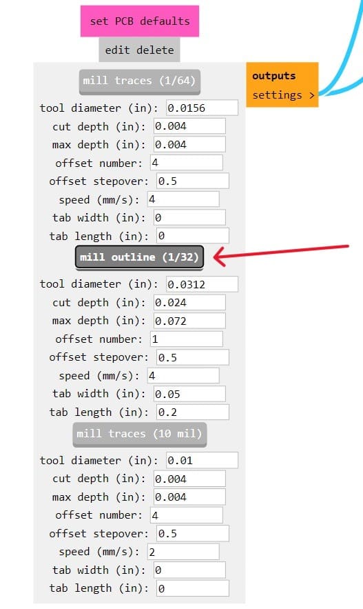
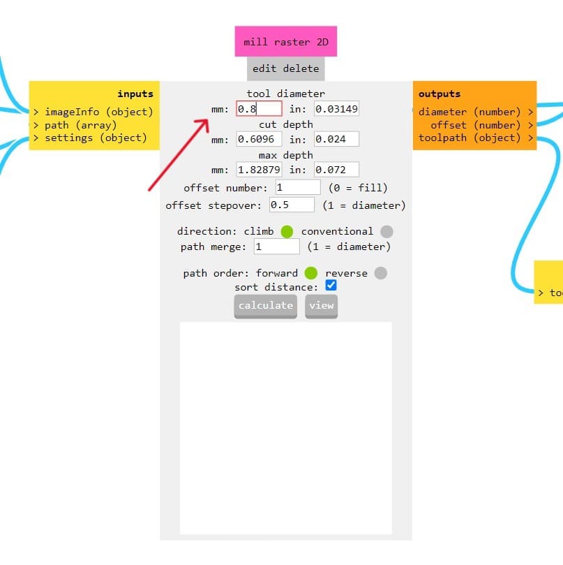
- PCB Frame: For the PCB frame, the settings to changte were kinda different. The first thing to do is uploading the frame image and inverting this image, next I clicked on the "mill outline (1/32)" option, I changed the tool diameter to 0.8, and set the origin to 0 and turned on the edit delete button.
- Processing The Program: If you complete all the steps, you can click the calculate button that is on the middle box. After clicking this button, you will see a different webiste with the routes that the cutting tool will follow to complete the PCB.

To download my files for the cutting machine, you can click here.
Cutting the PCB
After having the programs needed to use the SRM-20 cutting machine, you will need to download the drivers and programs required to use this machine. To download all these files, you can visit the official SRM-20 website were you can find a tutorial. The link to the website is this one. To finish the cutting machine configuration, you will need to have connected the machine to your computer using an USB. With the machine connectd, you will open the VPanel software were you can find the next things and functions:
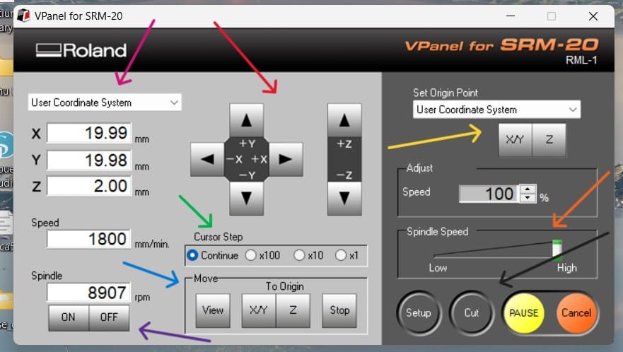
- Moving Panel: Marked with a red arrow, we have four buttons to move the tool on the X and Y axles and another two buttons to move the Z axis.
- Cursor Step: Marked with a green arrow, we have the cursor step options, these options are used to move the tool in four different speeds.
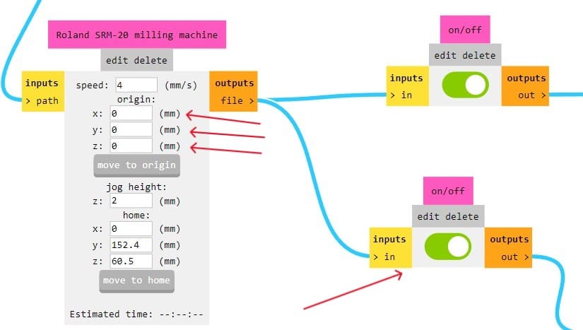
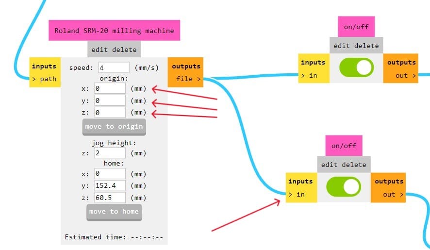
- Move: Marked with a blue arrow, we have the move buttons, were we can automatically move the tool to an specific saved positiion (the origin position).
- Spindle: Marked with the purple arrow, these buttons can turn on or off the spindle.
- Other Information: Pointed by the pink arrow, we have some useful information, like the tool position or the spindle speed.
- Set Origin: Marked with the yellow arrow, we have the buttons to set both of the tool's origin points. These points points are the X and Y axles and the Z axis.
- Spindle Speed: With an orange arrow, we have a bar to set different speed of the spindle.
- Setting Buttons: Pointed by the black arrow, we have four different buttons, but I only used three of them. The "Cut" button is used to upload the cutting files, the "Pause" button is used to stop the cutting process and the "Cancel" button is used to permanently stop the cutting process.
Now that we know how to use the Vpanel software, it is time to prepare the machine. This are the steps to prepare the SRM-20 cutting machine:
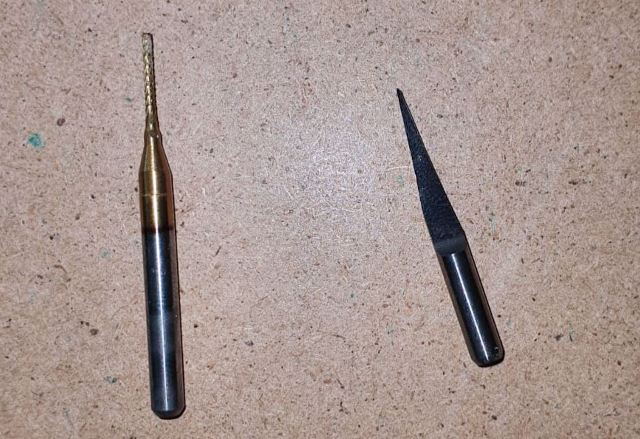
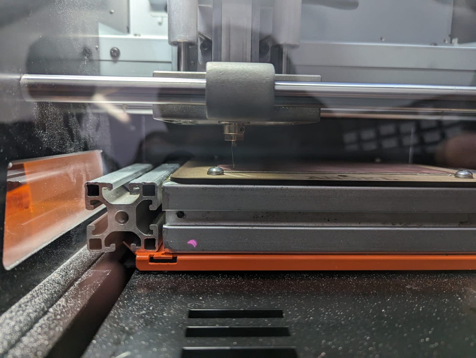
- Changing the tool: Before moving the tool or setting the origin, we need to change the machine tool. For this week, we used two different tools, the first one is a V cutter and the other one is a small milling cutter.
- Putting the Copper Plate: After changing the tool, it is time to paste the copper plate to the sacrificial bed. After that, you should locate the sacrificial bed (with the plate) in the SRM-20.
- Setting the Origin: The process of setting the origin, in this case, consists in locating the tool at the left down corner of the copper plate and then, you should bring the tool closer to the bed. You should set the tool close to the plate, but at a really close distance between the plate and the tool, you should loose the tool until it touches the plate. After that, you should turn on the spindle to low the tool a little bit more.
If you completed the steps succsefully, the next thing to do is clicking the cut button, and selecting your file. It is important to mention that the programs used for this PCB need a different tool. For the PCB paths I used the V cutter, but for the PCB frame, I used the milling cutter. This is not a big problem, because both of them share the same X and Y origin, but for the tool changing, you will need the set the new Z origin for the tool changed. This Z origin process is the same used for the V cutter.
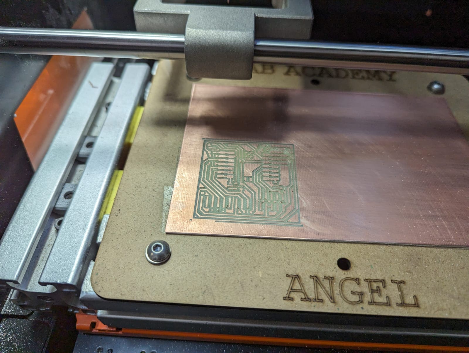
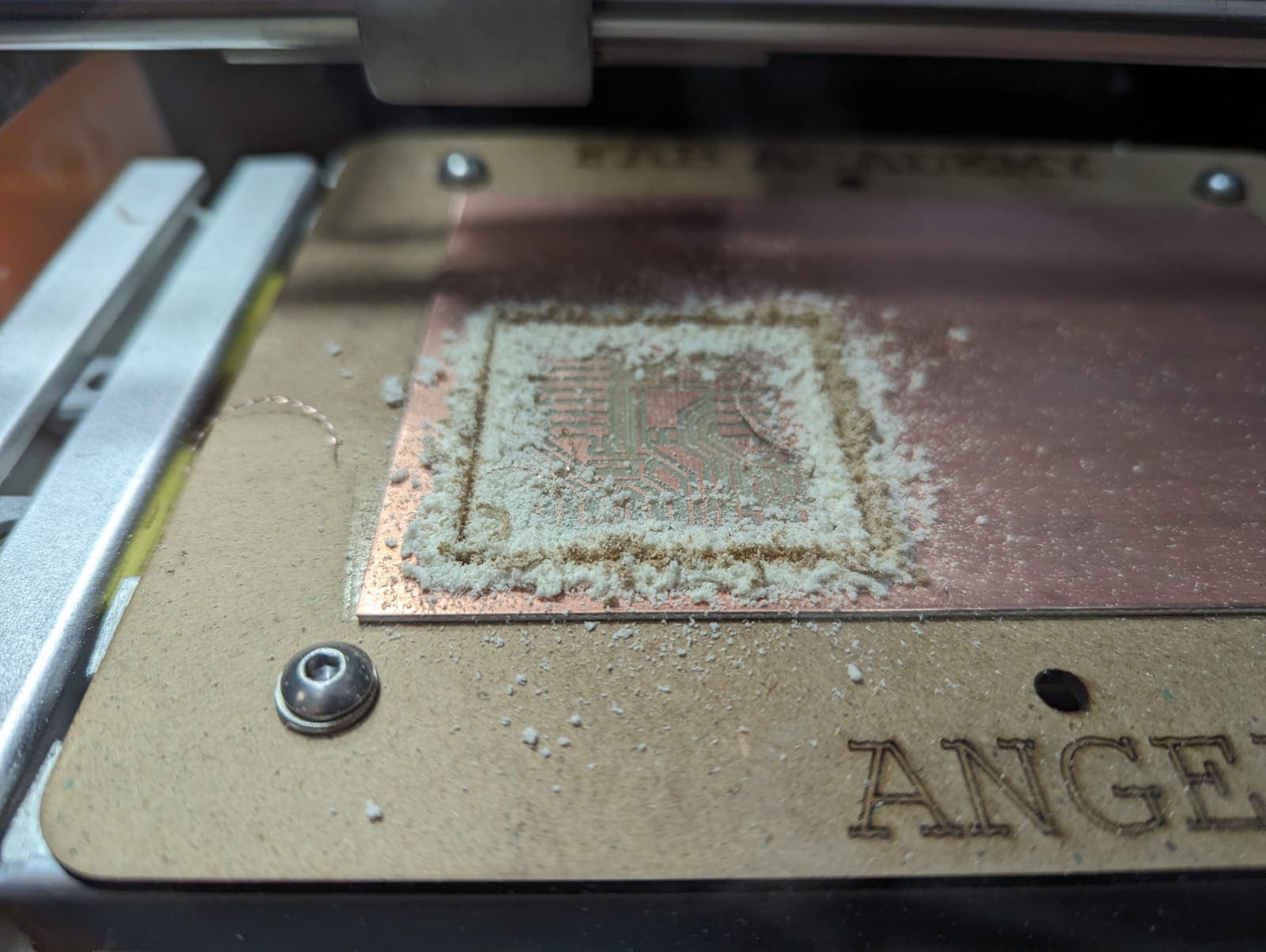
If you have some doubts wuth the machine settings and preparation, you can check this FabLab Barcelona link. Now, if you did everything right, this is hiw the PCB should look like:
Time to solder
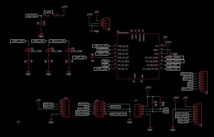
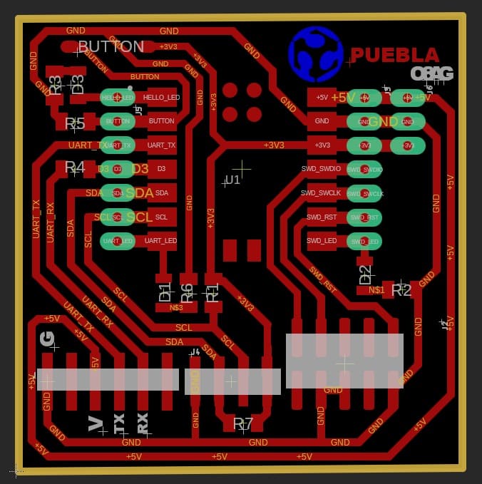
To start soldering, we should know what we are going to solder and the places where each component should be solder. To get this information, I have the connections diagram and the PCB digital design (in general terms, we are using a Seeed Xiao, 16 pins, 3 LEDs, 1 button and 7 resitances). These are the images needed to create an useful PCB:
Now that we have the diagrams to check the components needed, it is time to start soldering. This PCB uses SMD components instead of true holes components. This type of components have the characteristic that they are soldered directly on the top part of the PCB because they don't have large pins that pass through the PCB. This type of components are also smaller than the usual ones. So, thanks to these characteristics, the soldering process is, in my opinion, more difficult.
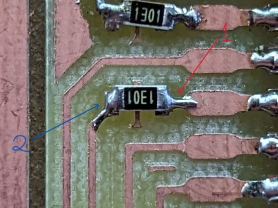
This was my first time soldering SMD components, but the soldering process, was not as difficult as I thought it would be. To solder the SMD components, we should apply tin on one of the path sides, then we should solder that side of the SMD, and finally, we should solder the other side of the component. Here is an image that shows this process in a better way:
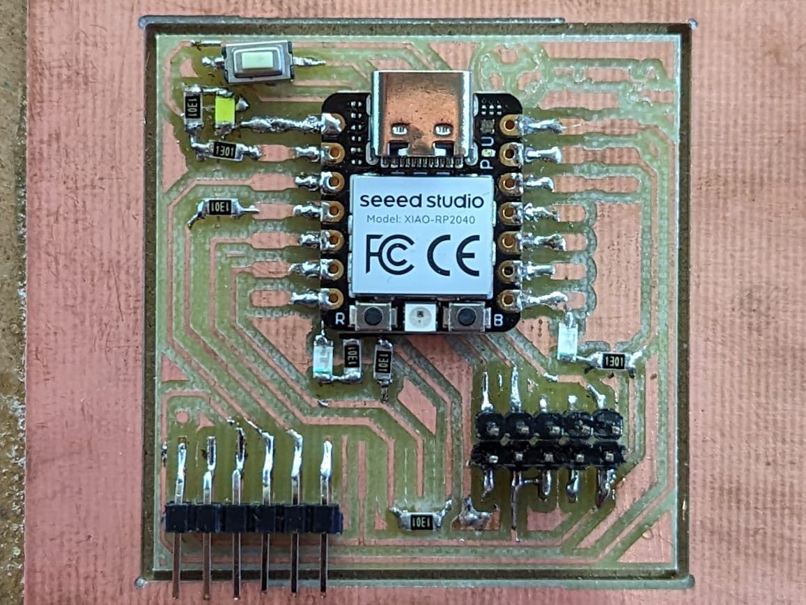
This is the process I followed to solder all the components. After some hours soldering, this is how my PCB looked:
Programming Time
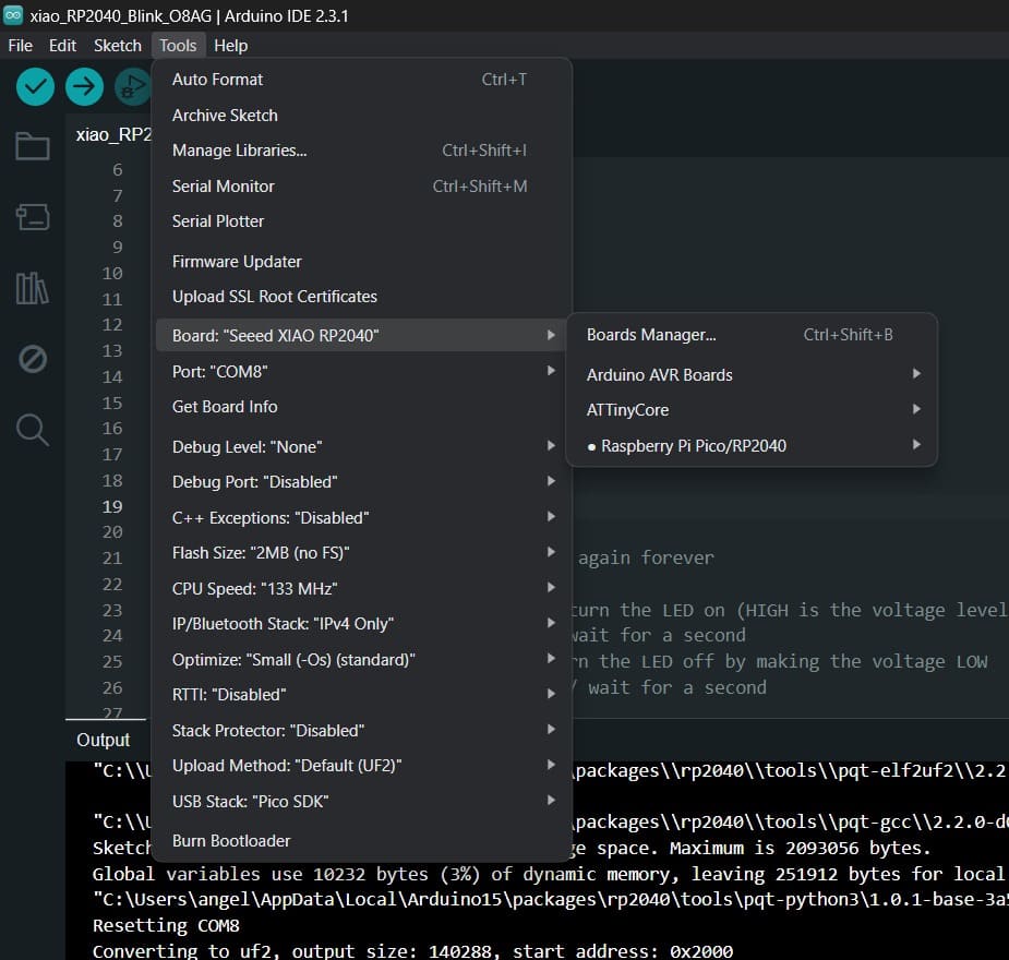
Now that I have a beautiful PCB, it is time to check if it works. To do this, I am going to connect the Seeed Xiao to my computer to upload the code given by my evaluator. To upload the code, I am using the Arduino IDE software with the Xiao board package. If you don't know how to install and used the Xiao package, you can visit this link. Now that we have the board package, it is time to select the USB port and the Xiao board. This is the configuration needed to upload the code:
The code that I am using for this week, is this one:
Finally, it is time to click on the "Upload" button of the Arduino IDE and check if our PCB is working correctly. This a demostration of what the PCB is suposed to do: