12. Molding and Casting
On this week I worked on designing a mold, cutting this mold and using it to create something. For this week, I didn't design the mold's figure. I downloaded the figure in a STL format and imported it to SolidWorks. To visit the group's week website, click here.
Designing the Mold
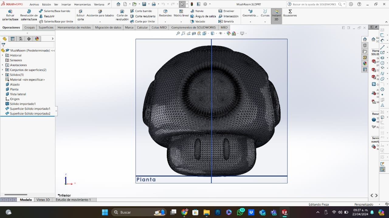
For the mold I checked different models of the Super Mario mushroom on the internet. I found a nice model of the mushroom for free on Cults 3D, I downloaded the STL and imported it into solidworks to work with it. To visit the mushroom's STL download page, you can click here.
Now, I am going to explain how I created the mold using SolidWorks. This was an easy process with simple operations.
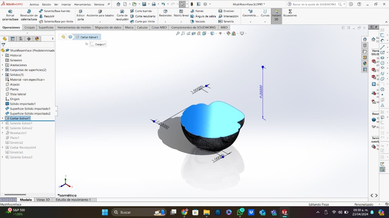
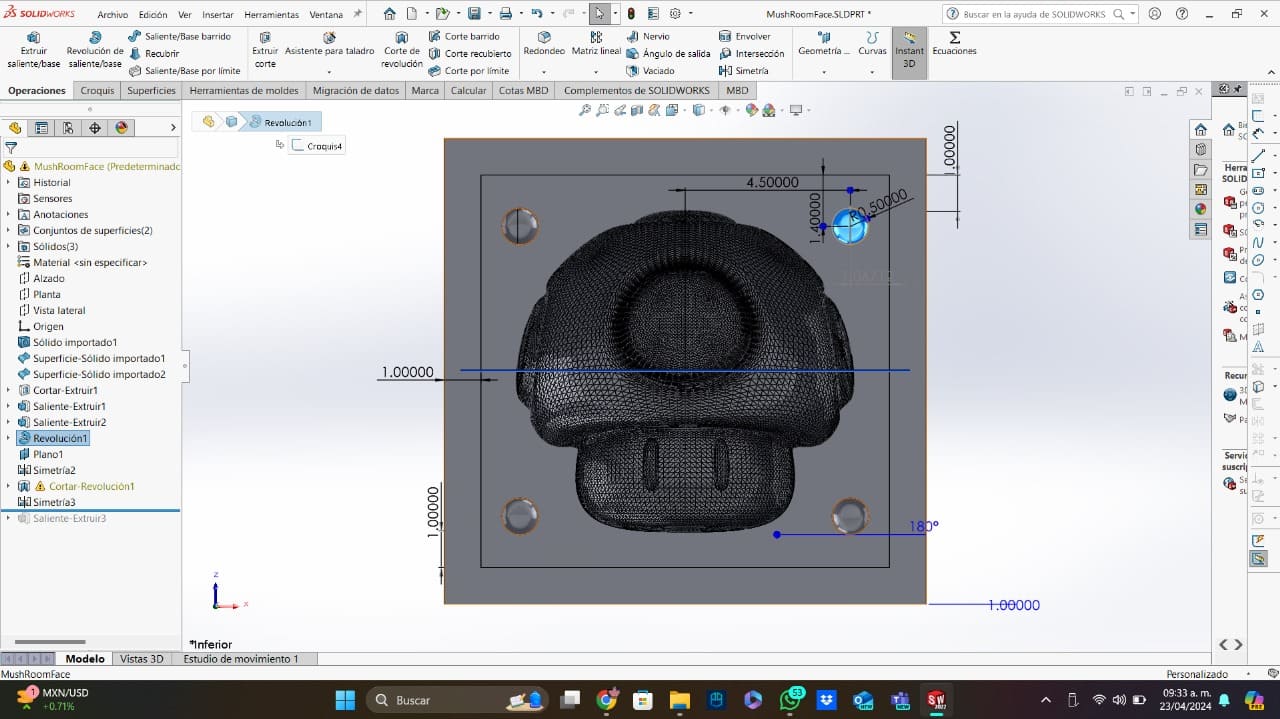
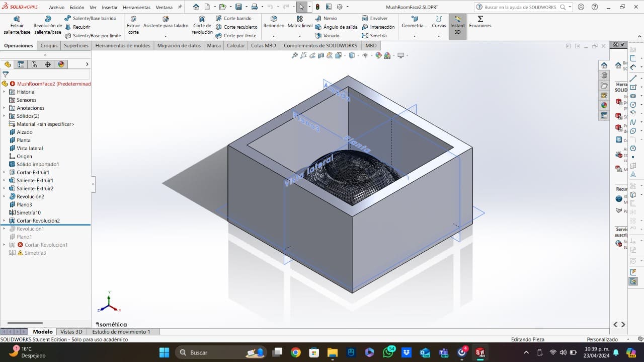
- The Half: The first thing I did, was deleting the half part of the mushroom using a pocketing operation. The dimensions of the pocketing square aren't important.
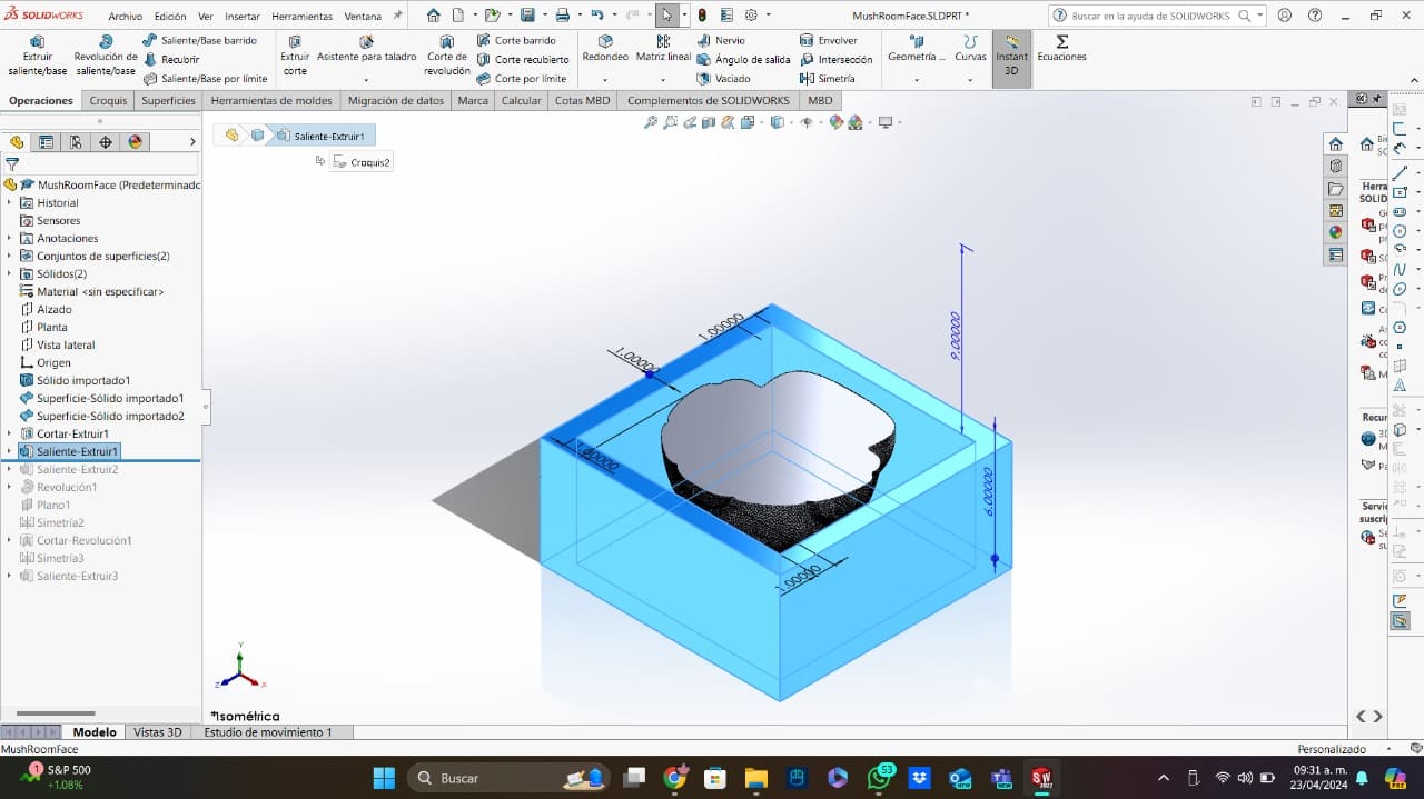
- The Margins: Now that I only had a half part of the mushroom, I created the mold margins using the same plane of pocketing but extruding them in the opposite direction.
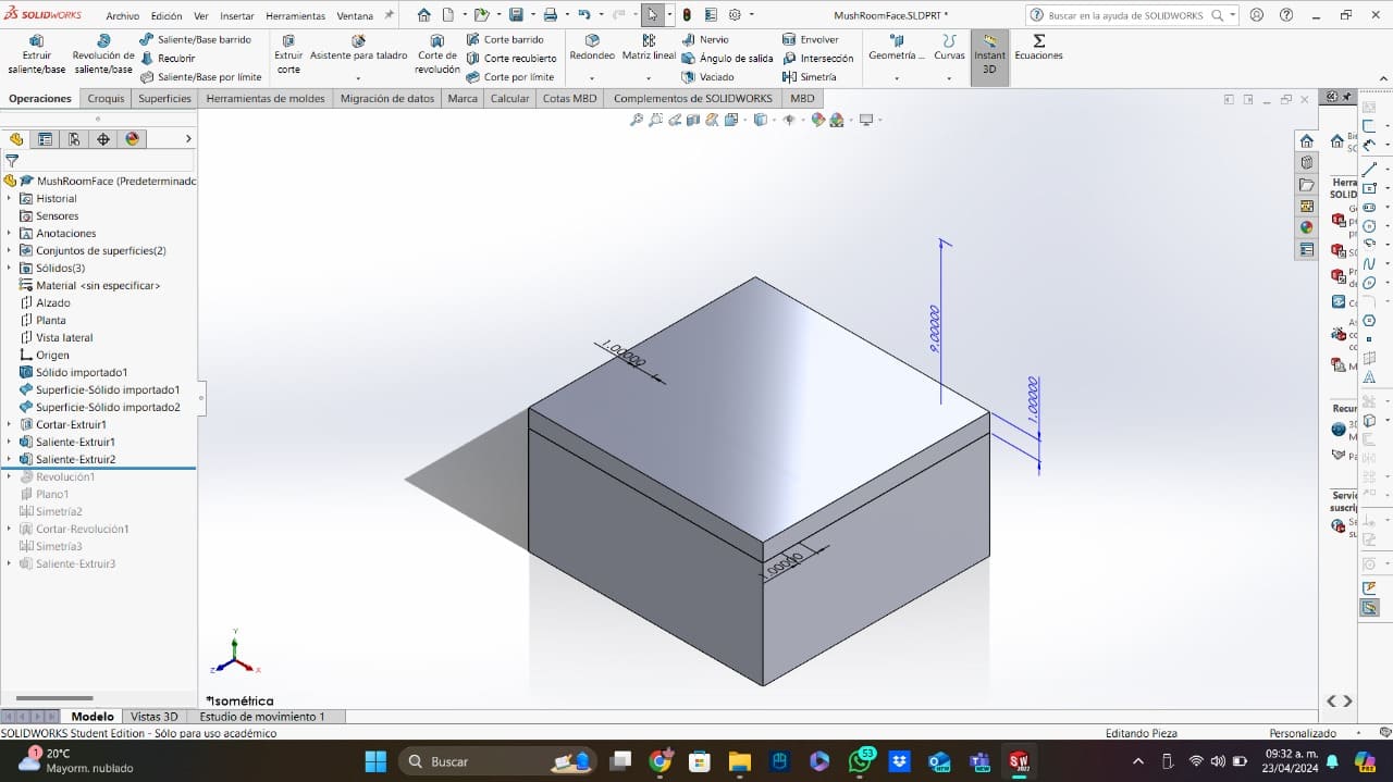
- The Bottom: Using one of the margins plane, I created a big square with the same dimensions of the margins and I made a small extrusion to create the mold floor.
- The References: I made half spheres in the 4 corners of the mold to use them as references when putting the molds of both parts of the mushroom together. These references serve to assemble both molds exactly and prevent the part from moving. Two of the references were extrusions and the other two were pockets.
- The Other Half: For the other half of the mushroom, I literally made the same operations, but in the opposite direction. The only thing that I changed were the references, I mirrored them in order to make them fit with the first half (the two extrusions now are pockets and vice versa).
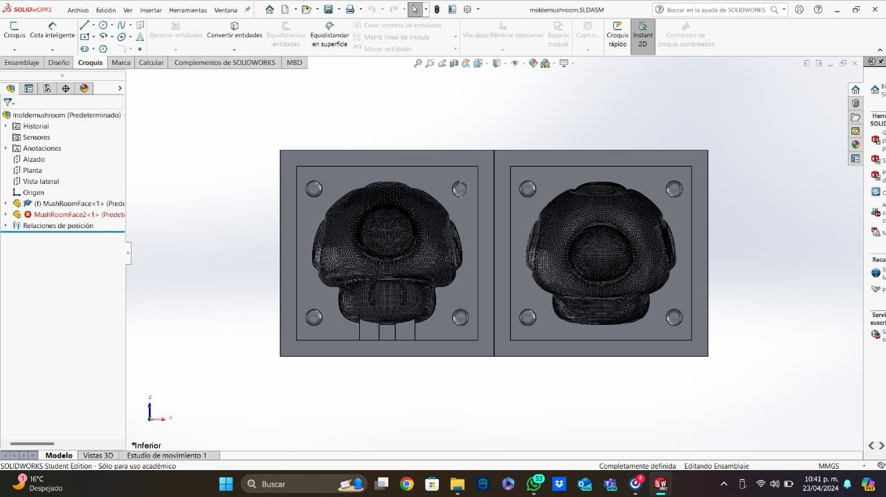
- The Mold: Now with the both molds of the mushroom, I created an assembly with both of them joined together. I saved this assembly as a single STL part.
Cutting Process
To create the mold, my advisors gave me a block of jewelry wax that I was going to be able to cut. In my case, I used the Asia Robotic CNC found at my university. To create the code for the router, I used the VCarve 9 program (it is important to use at least this version of thew program). To learn how to use the VCarve program, you can visit the week 7 clicking here.
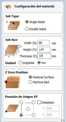
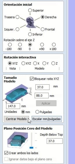
- Setting The Mold: To create the G-code, I first set the dimensions of the wax block and fit my mold on the block leaving the mushrooom (the part that will be cut) on the top of the block.
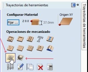
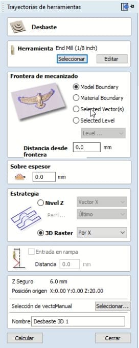
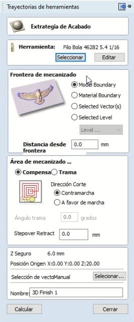
- Operations: For this process I just used 2 operations. The first one is called "Desbasting", this one consists in some initial cuts that will generate the basic forms of the mold. The second one is called "Finishing", this one will generate the details of the mold. The finishing process is also the longest.
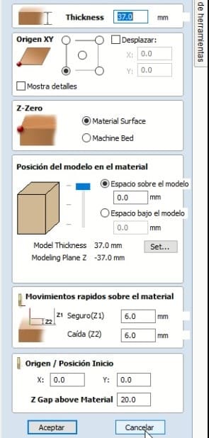
- Setting the 0: After clicking the first operation (Desbasting), a window for setting the zero will appear. In my case, I always set the 0 on the left bottom corner of the block.
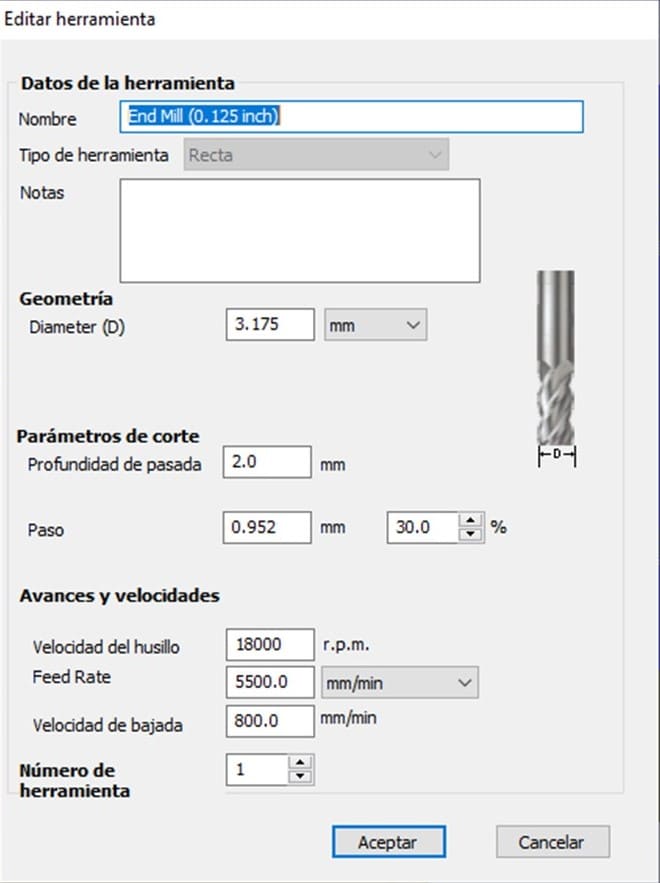
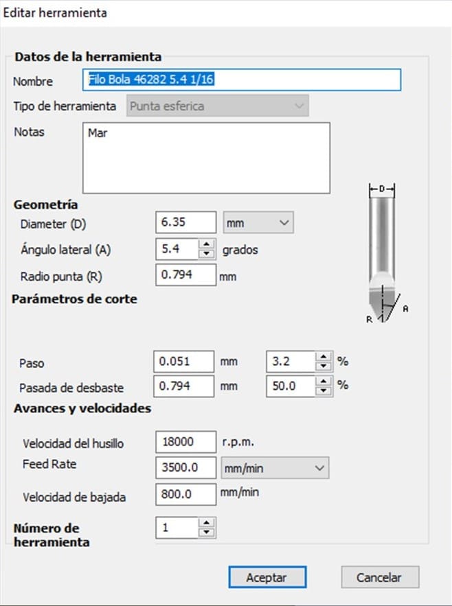
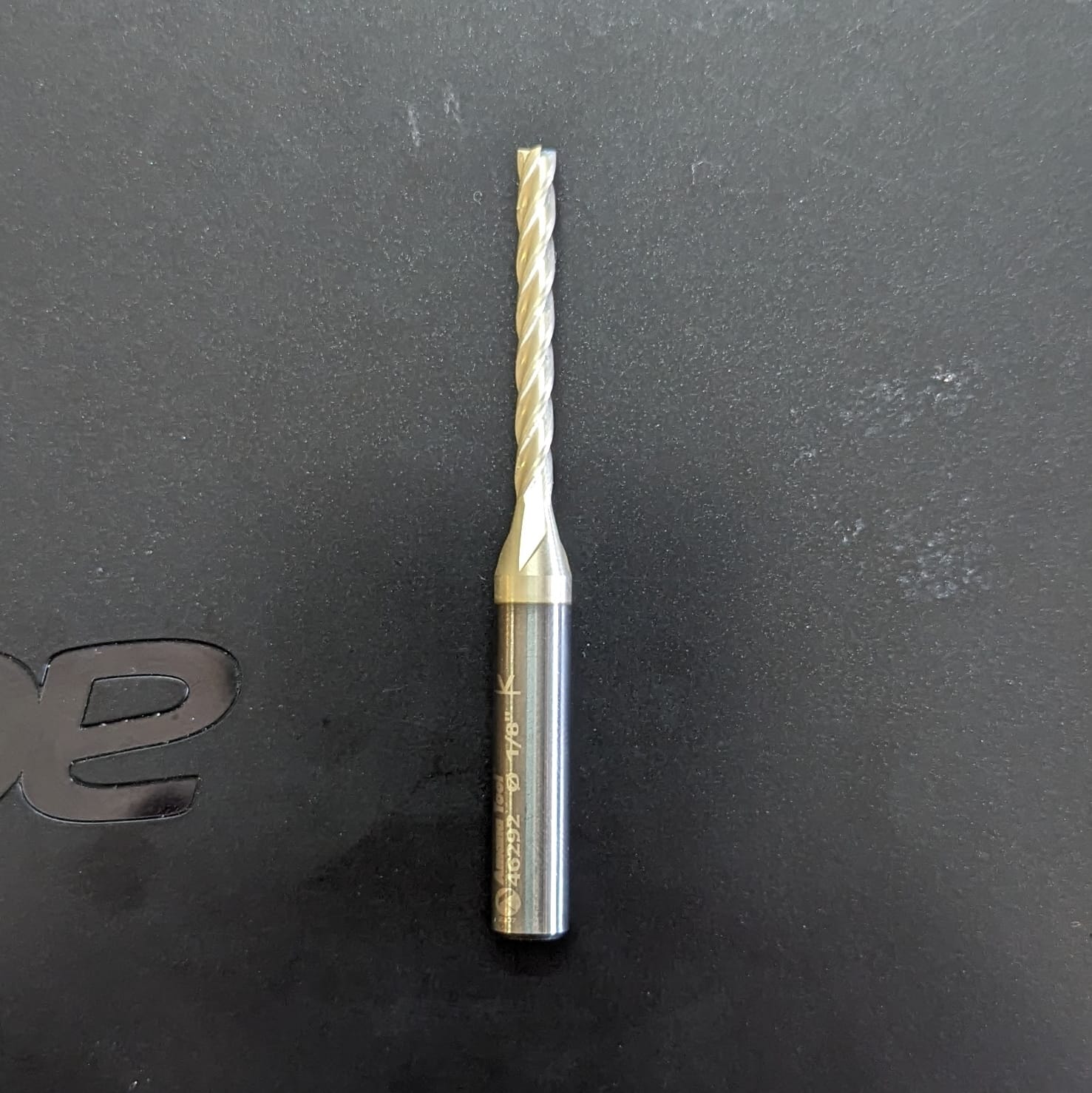
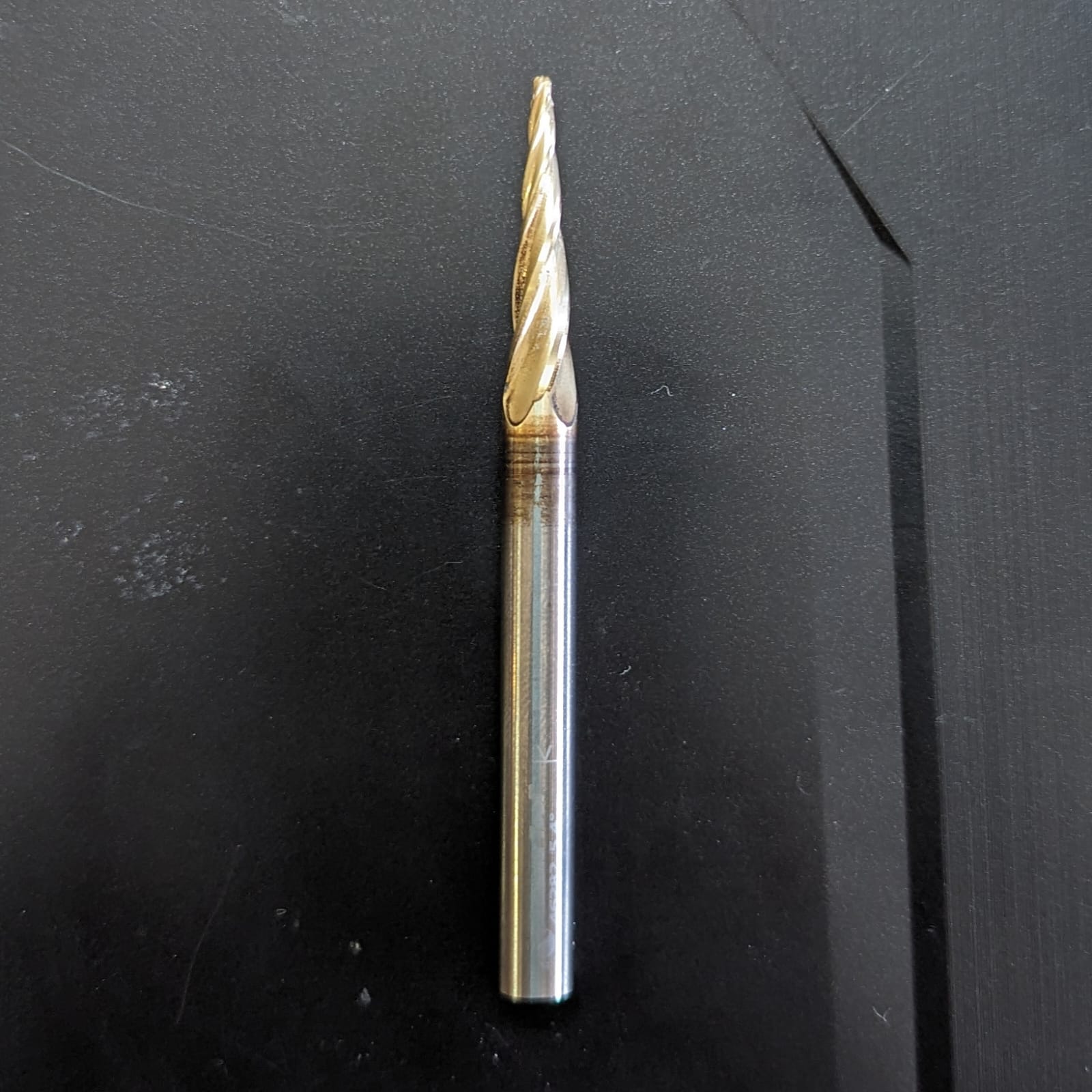
- The Tools: Like I said before, I used 2 different operations for my mold, so I used 2 different tools. The first tool, was used for the desbasting and the other one was used for the finishing. The images below show both of the tools:
- Setting The Operations: The following screenshots show the other settings used for each operations. After clicking "calculate", I saved each of the operations in different files to use the router.
For this week, I used the Asia Robotic CNC, this was my first time using this CNC, so I am going to explain the Asia Robotic control. The preparation process of the router is the same one explained on the week 7. To go to the week 7, click here.
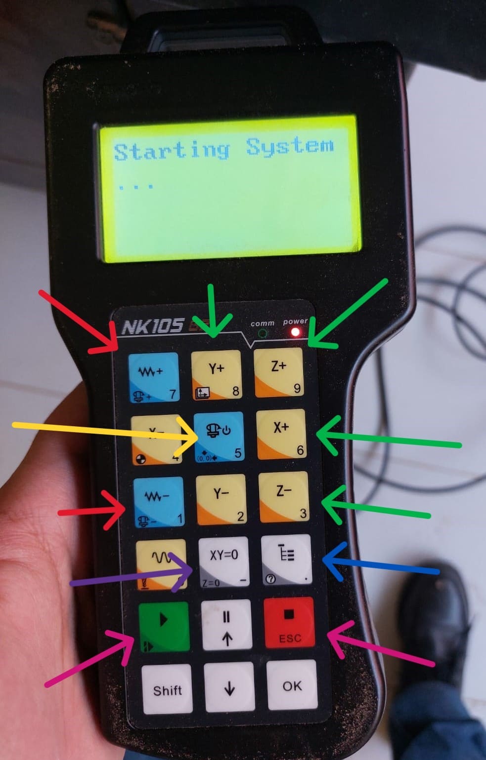
- Speed: Marked with a red arrow, we have two buttons used for changing the speed of the axles and programs.
- Axles: Marked with a green arrow, we have the buttons used for moving each axis.
- Files: Marked with a blue arrow, we have the button used for selecting the program to run.
- Origin: Marked with the purple arrow, this button is used for setting the tools zeros.
- Running: Pointed by the pink arrow, the green button is used for running the program, while the red one is used for stopping the program.
- Spindle: Marked with the yellow arrow, we have the button to turn on or off the spindle.
Now that we know how the Asia works, it was time to cut. This was a very easy process, just be careful with the program you select first.
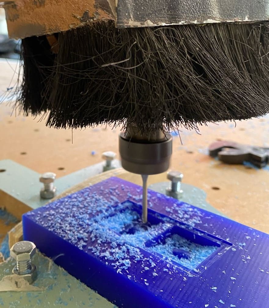
The first program and tool used was the desbasting one. When that program finished, I changed the tool and selected the finishing program:
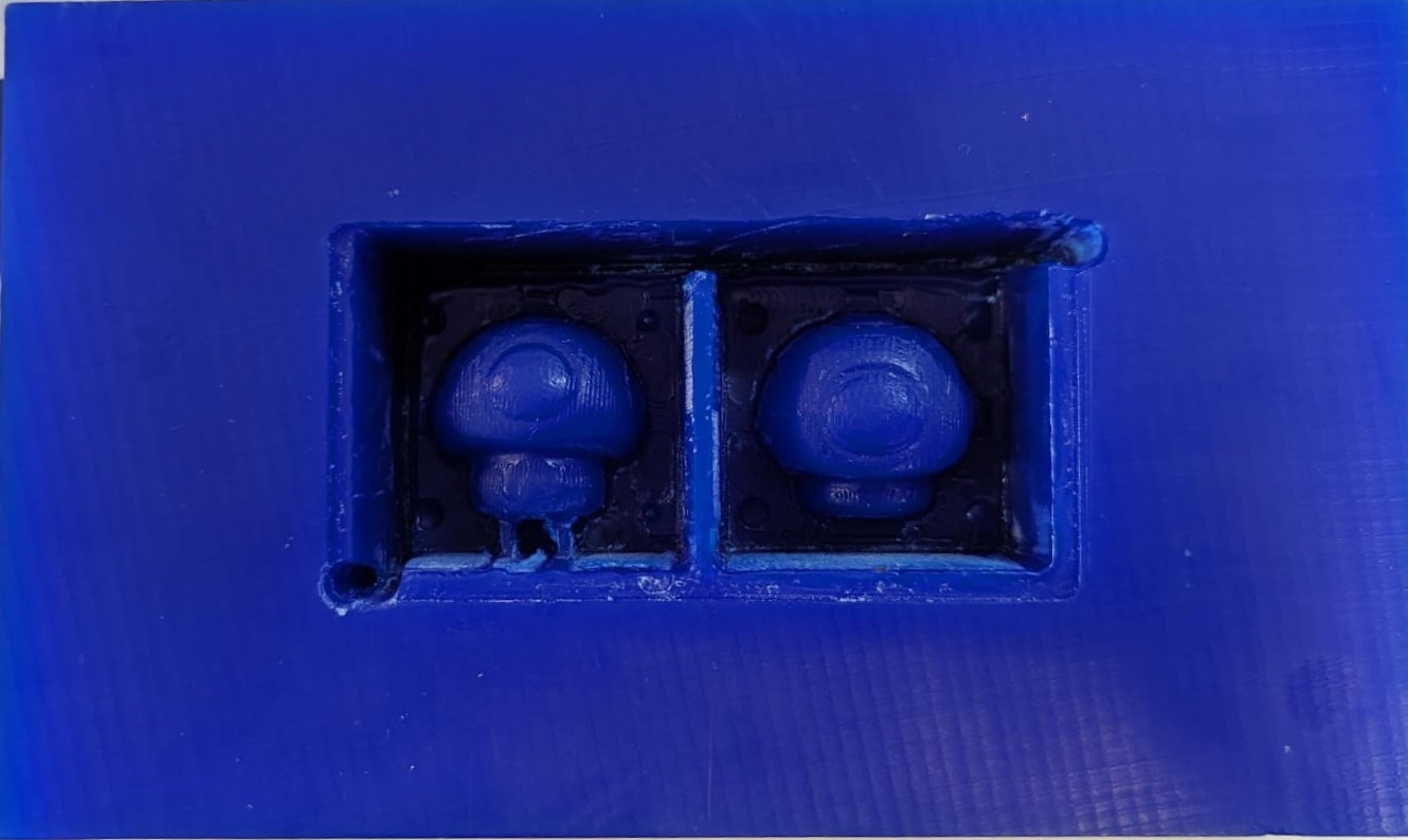
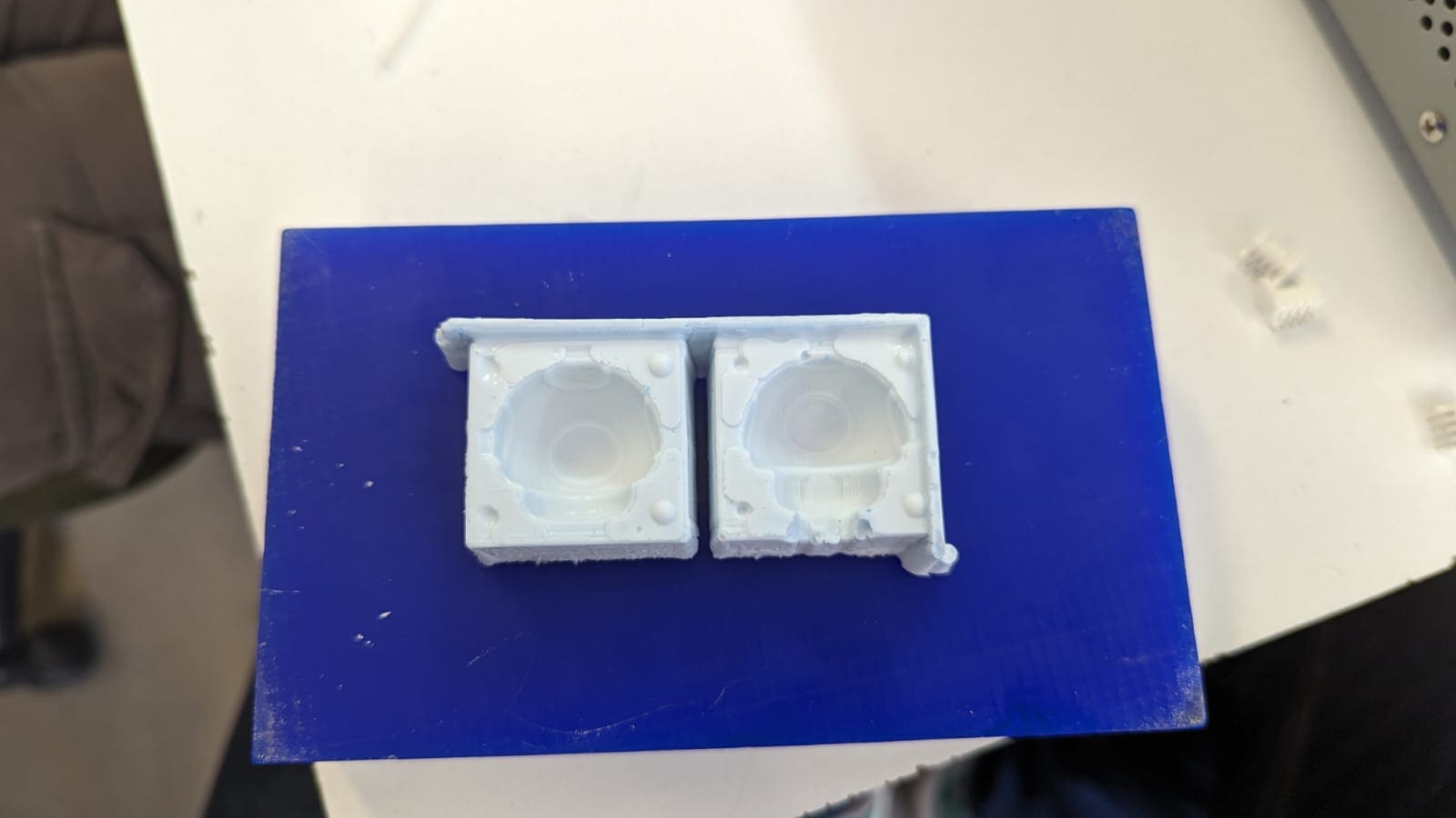
The result of the cutting and milling process is this one:
Silicone
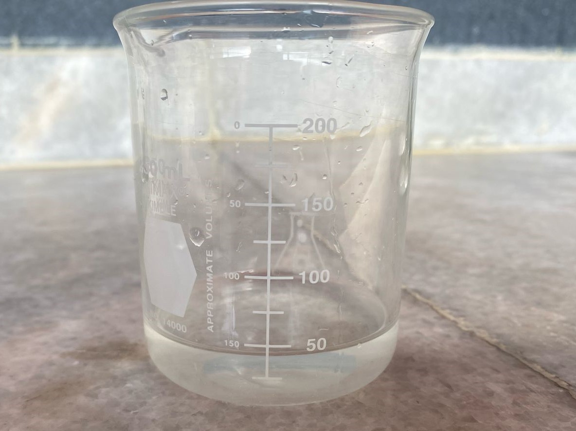
After cutting, it was time to mix the silicone and add it to the mold. For this task, I first checked the volume of my mold. I meausred this using a beaker, fulling the mold with water and then passing it to the beaker. With this process, I determined that that the volume of my mold was around 50ml. I passed the water from the beaker to a normal glass to make the silicone mix with the catalyst.
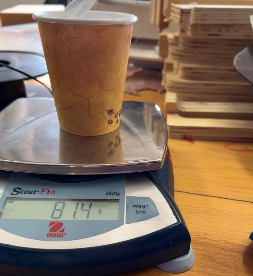
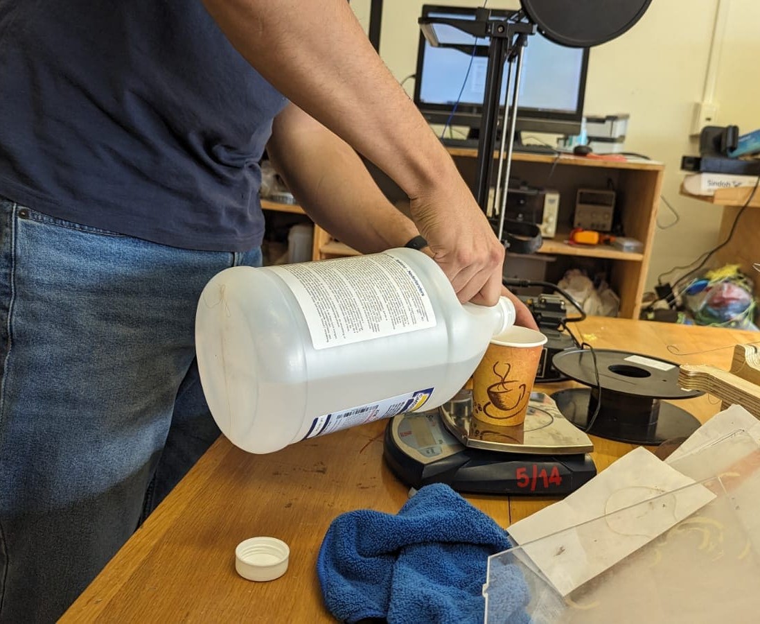
I filled the glass with silicone up to the mark I made, weighed it and then added 10% of the weight in catalyst. I added only the 10% because this was the relation the datasheet marked.
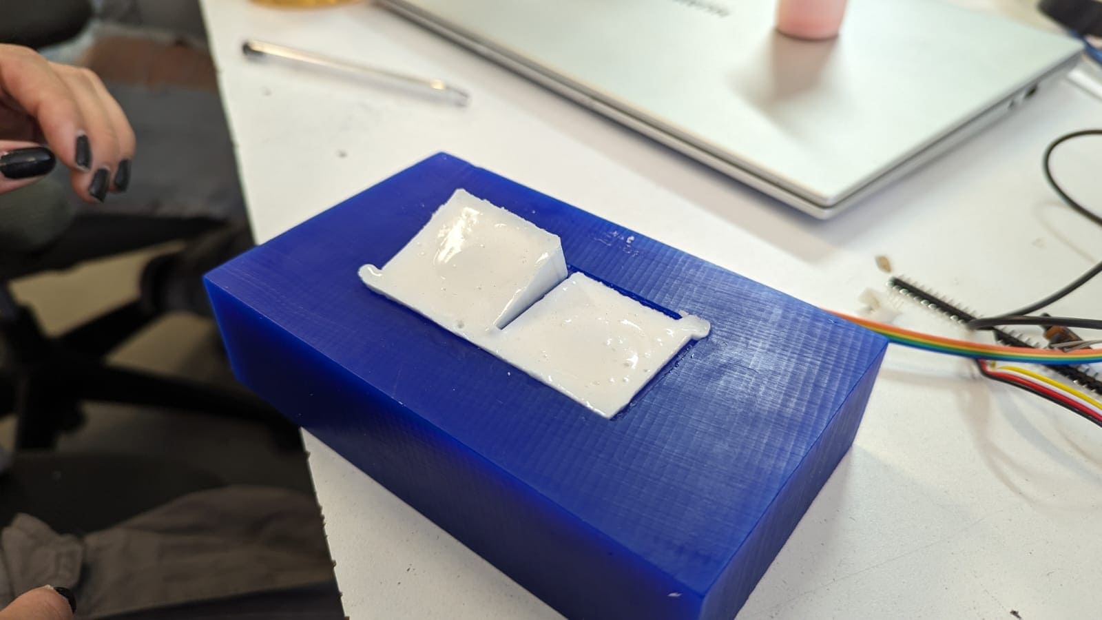
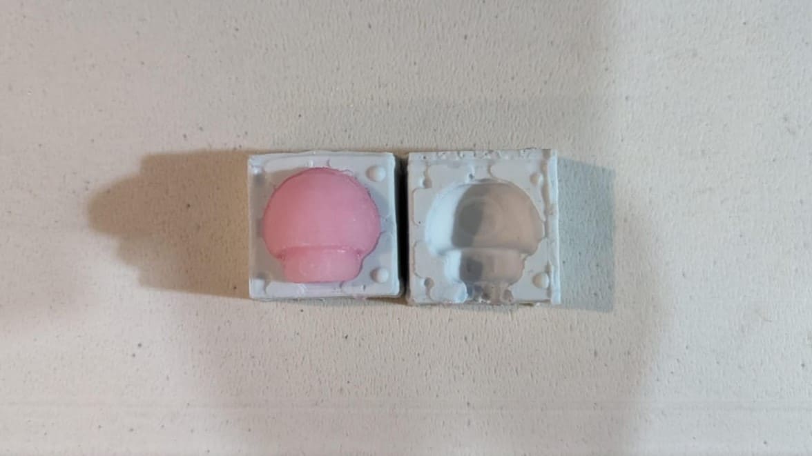
After mixing for a few minutes, I poured the silicone into the mold and waited around 20 hours to be able to remove it. Fortunately, the mold came out with very few bubbles, so the result was good.
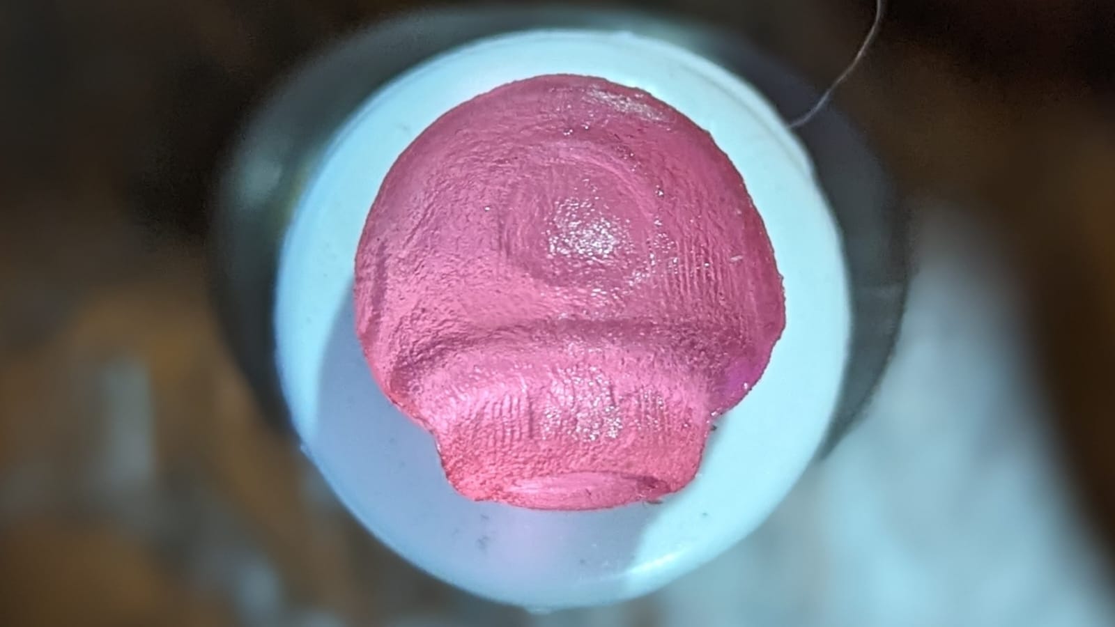
This silicone was not food grade, however, I had the idea of making a kind of gummy with the mold. For this gummy, I used a package of soursop jelly with more water than normal, poured it over the mold and waited for it to solidify. I put the gummy with the mold in the freezer to speed up the solidification process. After getting the amount of "gummy" needed for the mold, I made the rest of the gelatin as normal adding more water. But remember, this is not an edible piece, it is just for decoration. These are images of the result:
To download the files used for this week, you can click here.