10. Mechanical Design, Machine Design
On this week, I worked on a team task, making our own CNC machine. For this week, I helped my team designing the X and Z axles and using some of the Ibero's machines for adapting the components to our CNC.
We basically divided this project in non engineers and engineers. The non engineers were responsible of the designing of the machine and some minors details like the Arduino case. The engineers team were in charge of designing the mechanical and electronic parts (steppers, screws, nuts, etc) and the assembling part (including the adaptation of the materials bought). The non engineers team were also in charge of making the G-codes for the testings.
The X and Z Axles
For the first part of the CNC, I was in charge of checking the pieces my partners design and change them in order to make them functional for our CNC. I worked closely with my partner Juan Carlos Chavez. The pieces I changed were the X and Z axles ones:
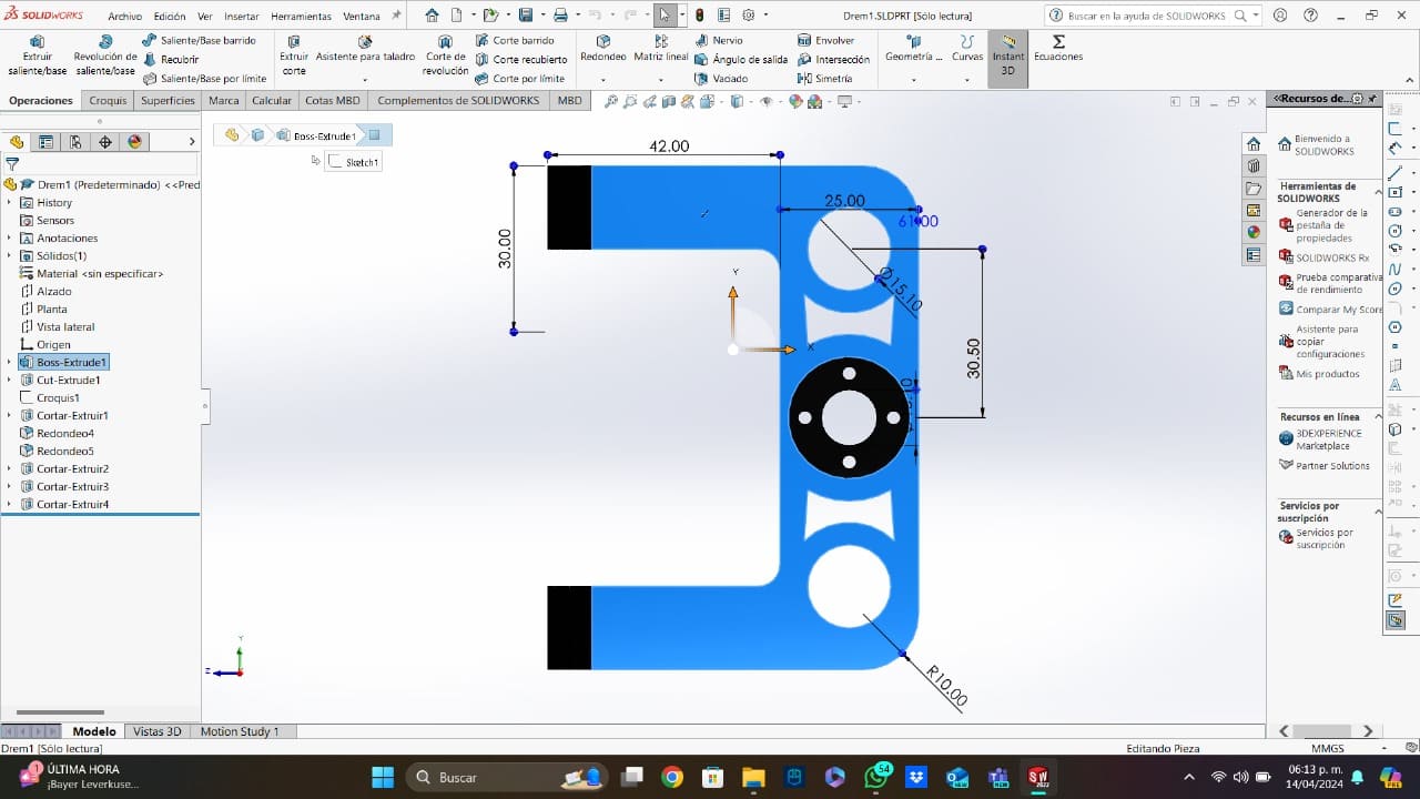
- X Axis Side Holes: The first thing I did was checking the X axis holes size. I changed the linear bearings size, because my teammate just created the holes as a guide and I created the slut for the nut. On this first design, we considered using a metric endless screw, a bad idea that will cost time and material.
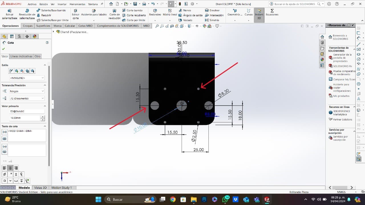
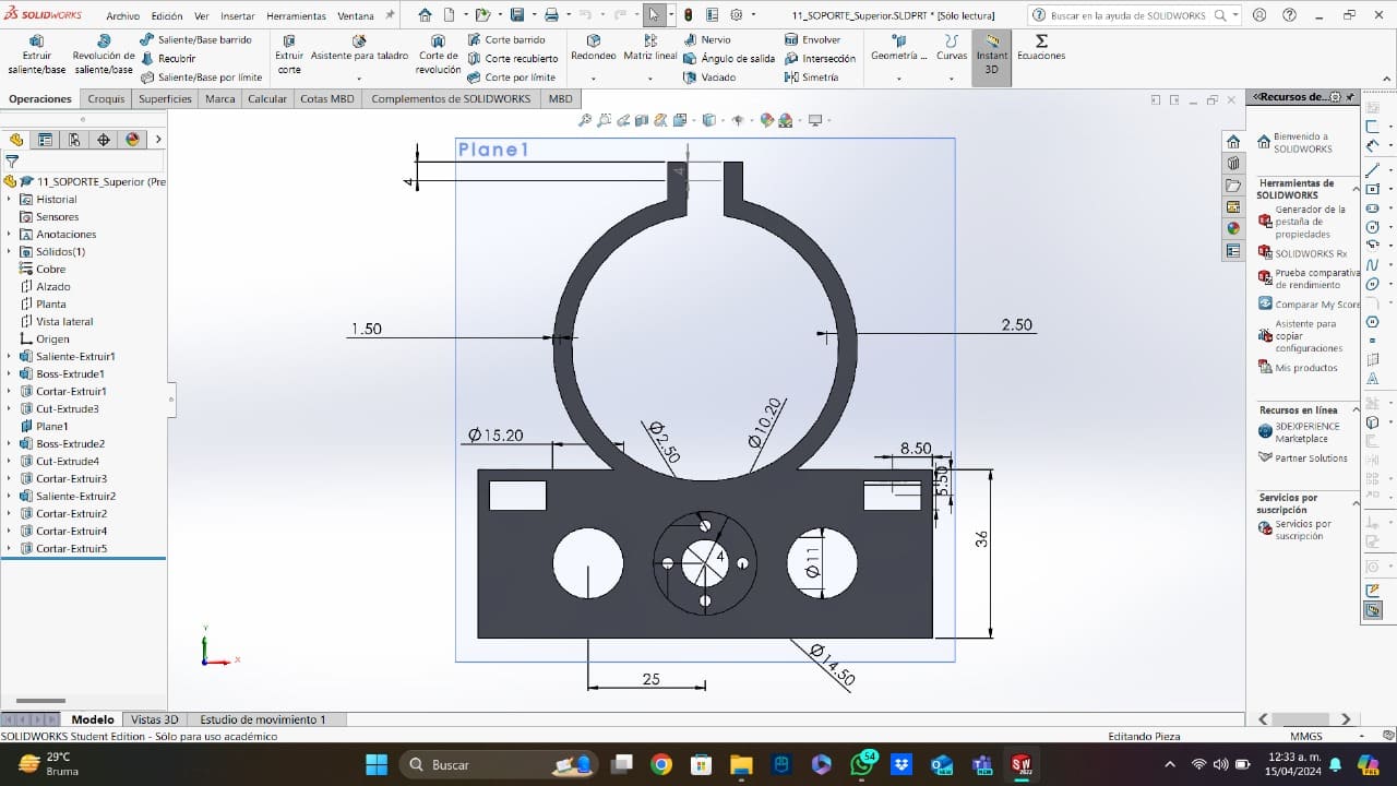
- X Axis Top Holes: Like the side holes, I changed the top holes to the right size for the steel rods and the endless screw. For this design, we considered leaving the screw coupling above the 3D printed piece, that's the reason why the middle hole isn't that wide. Finally, I added the screw holes to support the stepper motors. I did these holes using the measurements I found on Internet using the stepper model.
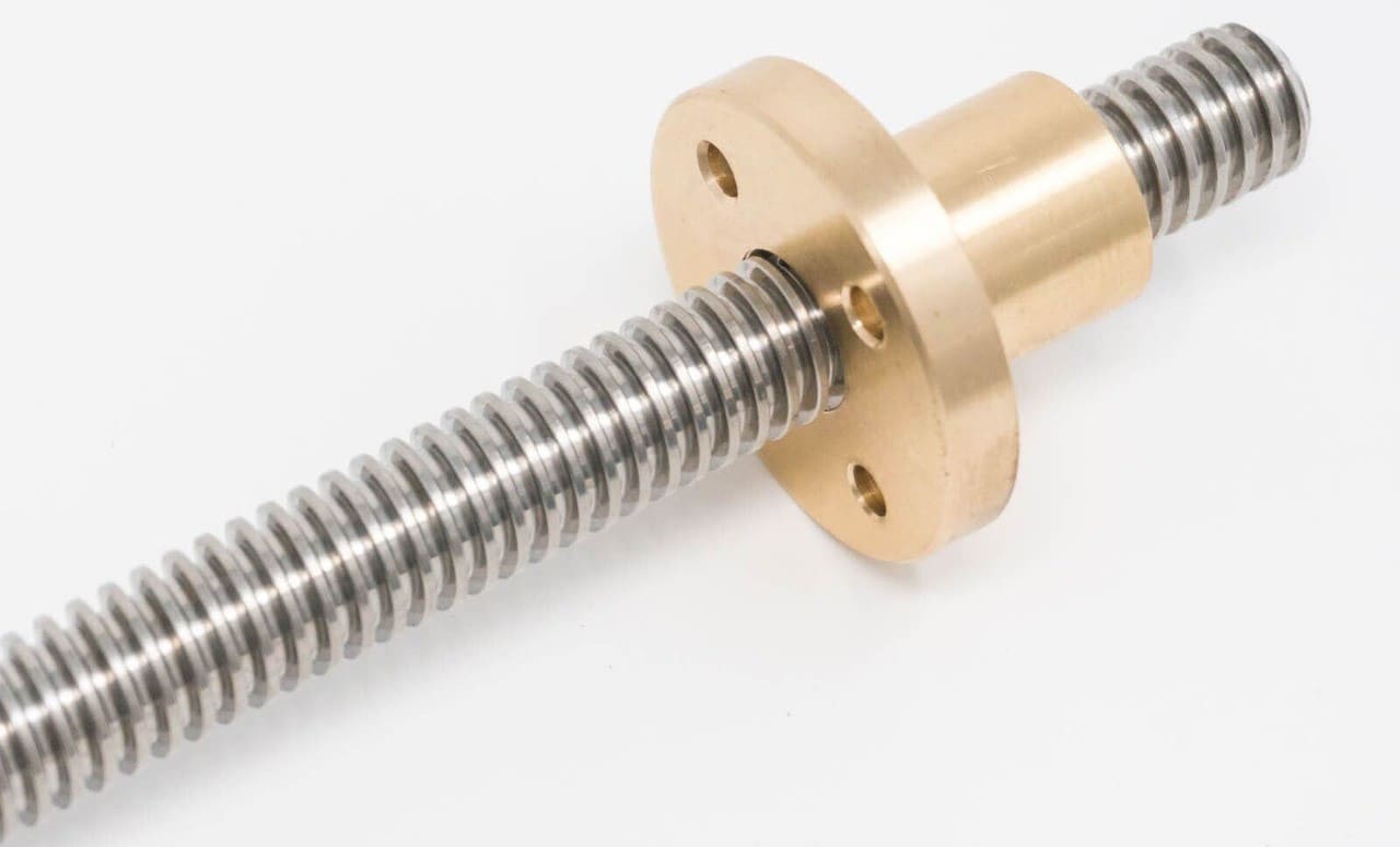
- Buying Before Designing!!: After changing the 3D models, I went to a 3D printer's store to look for the missing components. I bought the endless screw, the steel rods and the 8mm bearings. The big problem here was the endless screw, we modeled the pieces having a metric endless screw in mind, but we didn't find any metric screw, so I bought an ACME endless screw, that uses a different type of nut. This nut has a complete different form, so it was time to change all the models that uses a nut.
- X Axis Nut: After buying the ACME screw and its nut, it was time to change the nut slot from a metric one to the ACME one. This was kinda easy, I just changed the hexagon form to a circular form with the ACME nut sizes.
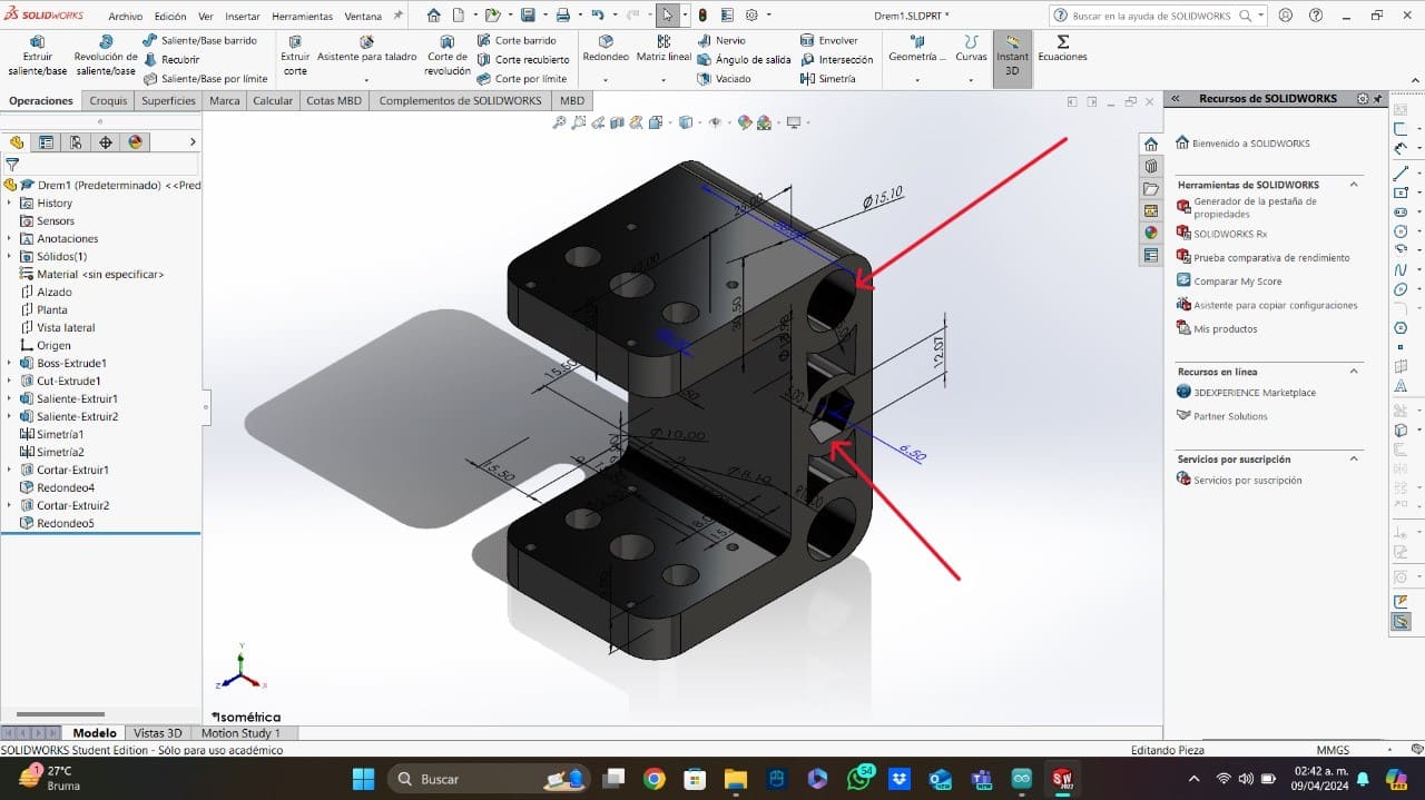
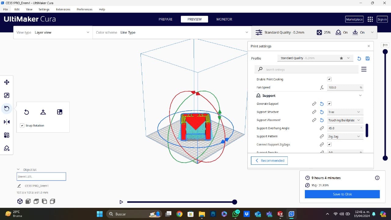
- Z Axis: For this axis, I changed the top part of the Dremel holder. I changed the lineal bearings holes size and I added the ACME nut slot, I also made the Dremel hole a few milimeters bigger.
Assembling
For the assembling part, I helped printing the pieces I modified and adapting the components to our machine measurements.
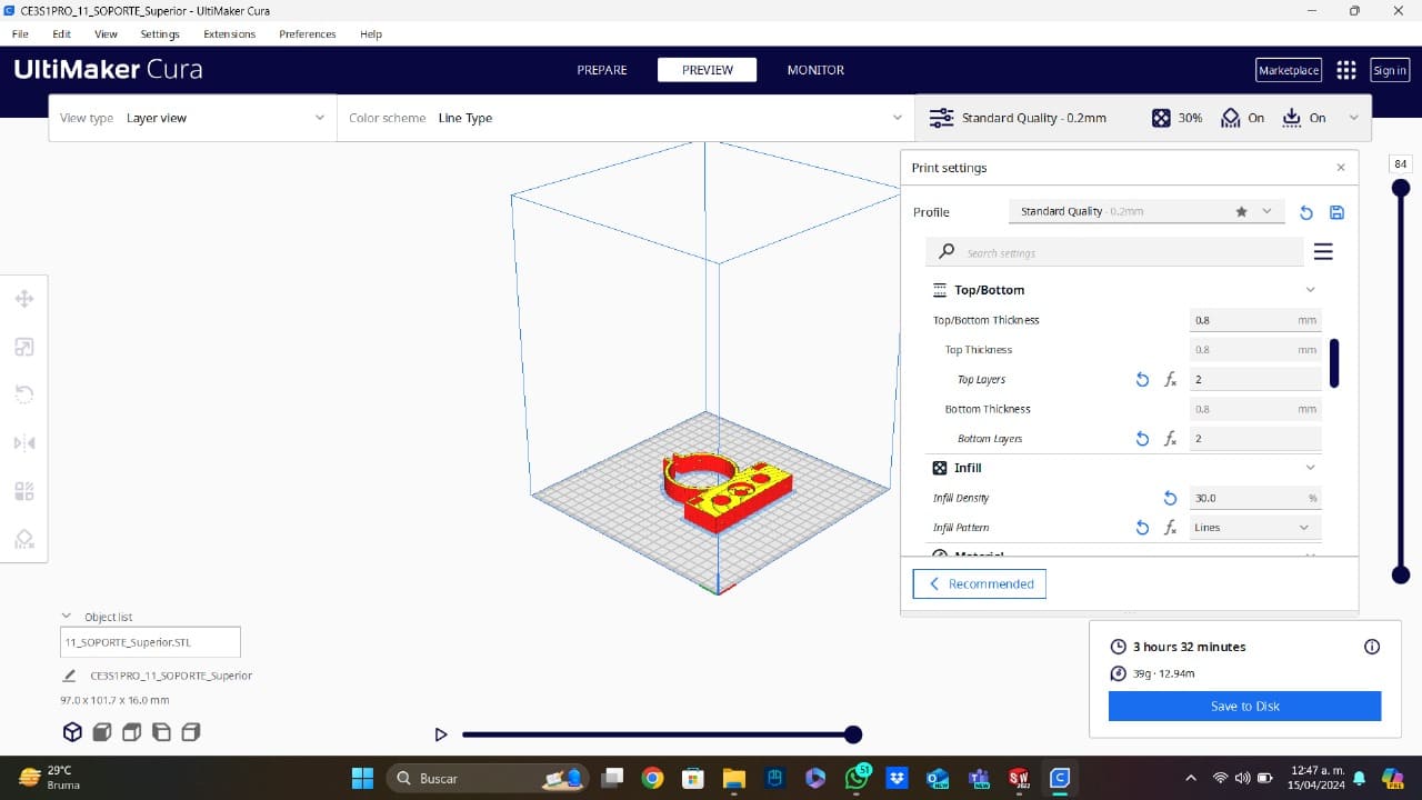
For the printing part, I first printed some testings using a low infill percentage. When the pieces were completely right, I printed them using 30% of infill. I used basically the same settings I used on my week 5. The settings I modified for the X axis piece, were the infill and the supports. Like I said before, I changed the infill percentage to 30% leaving the same pattern (Lines). I added a tree support useful for the screw and rods holes. For the Dremel holder, I only removed the tree support. The pieces I printed were the X axis one and the 3 pieces that the Dremel holder uses.
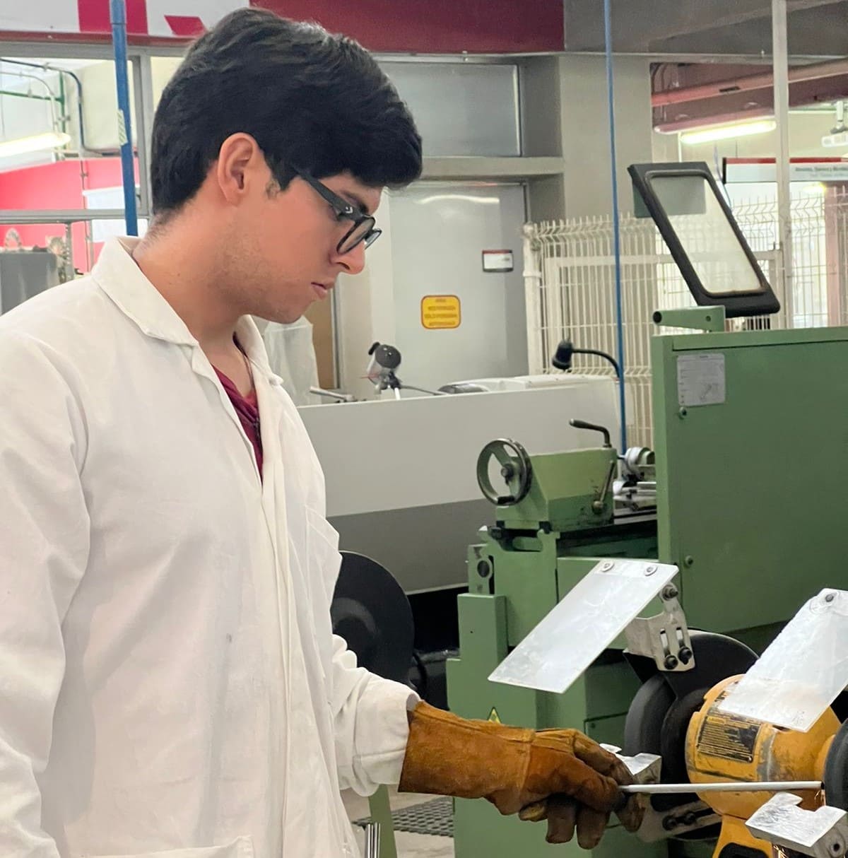
Finally, I helped my team cutting and filing the endless screws and the steel rods, adapting them to our machine dimensions (remember to use the safety equipment and be careful with the cutting disc!!). I also helped screwing some machine components (like the steppers), testing the steppers movement (making little corrections to some pieces if it was neccesary) and preparing the machine for the cutting tests.
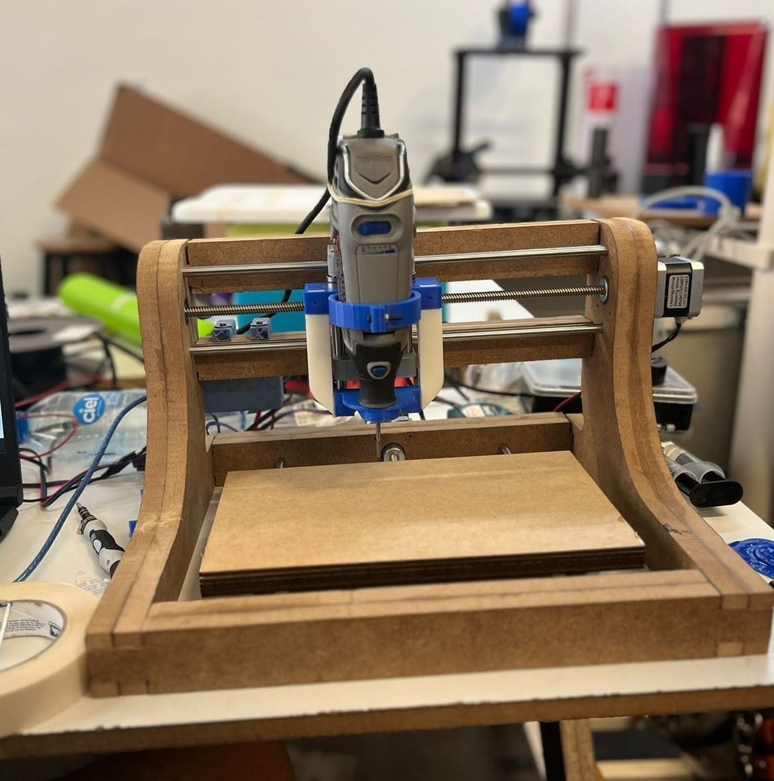
To download the files used in this week, click here. To download the pieces of the bed, clicking here. To download the case for the Arduino, click here. If you want to check the complete process used for the creation of the CNC, you can visit the team's website clicking here.