9. Output Devices
On this week I learned to use some output devices. In my case I used an OLED display that I will use in my final project and a servomotor. This was a week full of fails and it was harder than I thought. To fully understand this week, you should check the last week and the weeks mentioned there, you can click here to go to week 8. To visit the group website, click here.
OLED Display
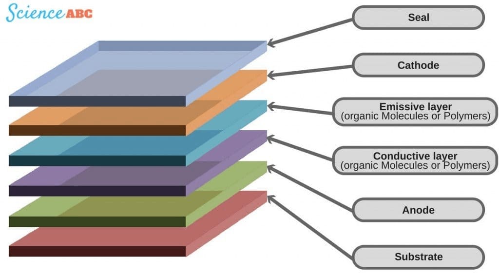
OLED is an abbreviation for Organic Light Emitting Diode. The traditional LCD screens have pixels lighting from a backlight, while the OLED screens are made out of organic molecules lighting the moment an electric current has been applied. This enables individual control over every pixel to help produce blacks, and a contrast ratio is improved since a pixel can be completely turned off, not just dimmed. The OLED displays are much slimmer, lighter, and more flexible than the LCD ones, and so they are highly desired in many applications like smartphones, televisions, wearables, and others.
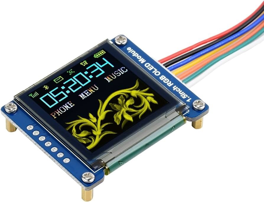
OLED display operates on the principle of using organic materials that emit light upon energization. These materials are sandwiched between two electrodes, one of which is transparent. Electric voltage of a given value applied across the electrodes forces electric current in the organic layers, this excites the organic material, allowing it to produce light. So, this type of organic molecule is designed in such a way that it decides the color of light and gives the panel of OLED any range of colors by combining the different types of organic compounds. The display used on this week has only one color.
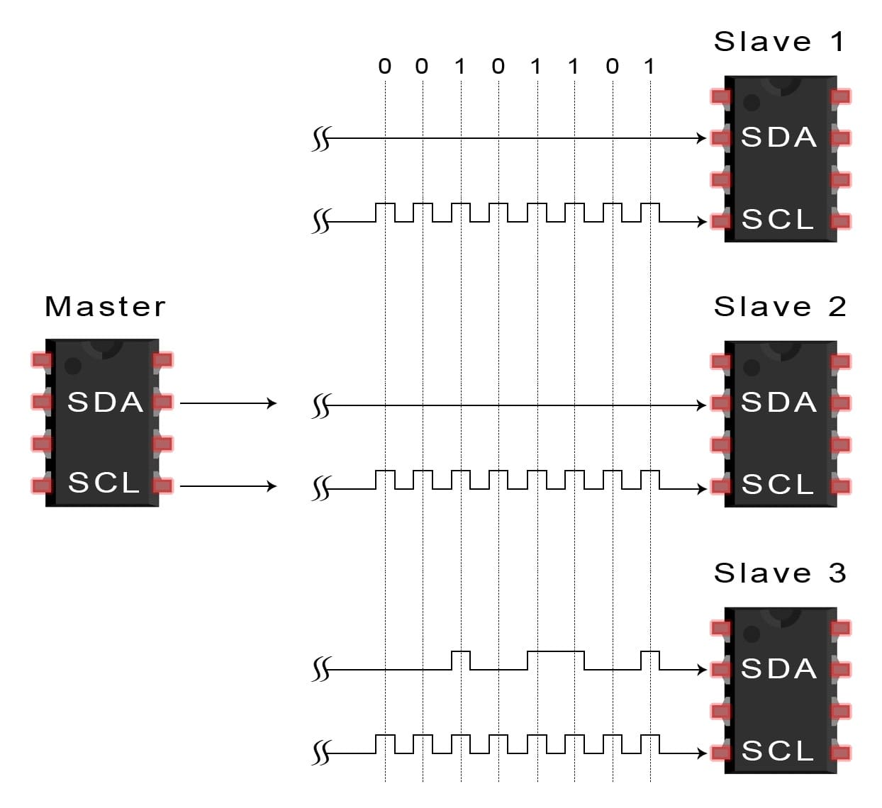
I2C means Inter-Integrated Circuit, and it is probably the most popular communication protocol that takes place between microcontrollers and devices, operating at a relatively low speed, like an OLED display. It is the bi-directional two-wire serial communication bus to control the operation of more than one slave devices (sensors, displays, etc.) by a single master device (microcontroller). The protocol uses only two wires, irrespective of the number of devices connected. The two wires are the Serial Data Line (SDA), carrying the data, and Serial Clock Line (SCL), carrying the clock signal used to synchronize the data transfer from host to peripheral device.
The process that I2C communication follows with an OLED display is that it sends a series of signals to address the display. It will first send a start condition, and then it will be followed by the address of the OLED display. If OLED is ready to communicate, an acknowledgment signal is returned. Later, the master device sends another command to the display device and again gets acknowledged by the OLED. It might contain the decision about what has to be displayed, changes in brightness, or a command for a single pixel to be turned on or off. It is the simplicity and efficiency of I2C that makes it the best choice for controlling OLED displays.
Fortunately, using an oled display with arduino development software is very easy, due to the open-source nature of the Arduino IDE. To control an OLED display there are many libraries that we can use depending on many factors, such as the power of the microcontroller, the flash memory capacity, among other things. For this week, I used the "TinyWireM" and "Tiny4kOLED" libraries. The first one is a lighter version of "Wire", library used to establish communication between an Arduino and i2C devices, adapted to more limited devices (in this case the Attiny44). The second library is specifically designed for the control of the oled display with a focus on the Attiny44.
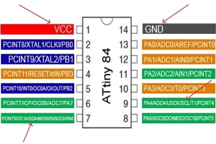
To connect the Attiny44 to the OLED display, they are neccesary only 4 wires. One for VCC, another for Ground, and the other ones for the SDA and SCL. In my case, I used the PCB y desgined the last week. I made the last week PCB thinking in using an OLED dispplay, so I had the necessary pins to connect the OLED Display. You can check the Attiny44 pinout here:
Now that the OLED Display is connected to the Attiny44, it is time to program it. I programmed my Attiny44 using an Arduino as ISP. You can see how to use an Arduino as a programmer on my website, to be more specific, right here. This is the explanation of the code used this week:
#include TinyWireM.h
#include Tiny4kOLED.h

#define pwmPin  3
#define enPin   4

#define buttonPin1 10
#define buttonPin2 7
#define buttonPin3 5
void prepareDisplay() {
  oled.clear();
  oled.begin();
  oled.setFont(FONT6X8);
}
void setup() {
  oled.begin(128, 64, sizeof(tiny4koled_init_128x64br), tiny4koled_init_128x64br);
  oled.clear();
  oled.on();
  prepareDisplay();
  oled.setFont(FONT6X8);
  pinMode(buttonPin1, INPUT);
  pinMode(buttonPin2, INPUT);
  pinMode(buttonPin3, INPUT);
}
void loop() {
  if (digitalRead(buttonPin1)==HIGH) {
    oled.setCursor(0, 0);
    oled.print("Button 1");
    }
...
  else if (digitalRead(buttonPin1)==LOW && digitalRead(buttonPin2)==LOW && digitalRead(buttonPin3)==LOW) {
    oled.setCursor(0, 0);
    oled.print("OFF     ");
    }
}
Before showing the video of the working code, I need to add that making the OLED work was harder that I thought. In my case, I lasted a lot trying to show something on the OLED, and thanks to this problem, I desoldered and burned 2 different Attiny44 microcontrollers. This was a desperate experience that I hope not to repeat. I also need to add that the Attiny44 is a very simple microcontroller to use with an OLED. This microcontroller has a very small memory flash thatmakes it impossible to use it optimally with the OLED display. I highly recommend to use a faster microcontroller like an ESP32 or a SEEED XIAO.
Here is the video of the Attiny44 working with the OLED display:
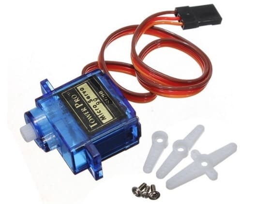
Servomotor
A servomotor is a special type of motor that is designed to move or maintain a specific angle or position. The reason why servomotors are very accurate is that they can be controllable and moved to an exact spot, as such are perfect for tasks that are needed for careful movement, for example, operating the arms of a robot or moving the control surfaces on remote-controlled airplanes.
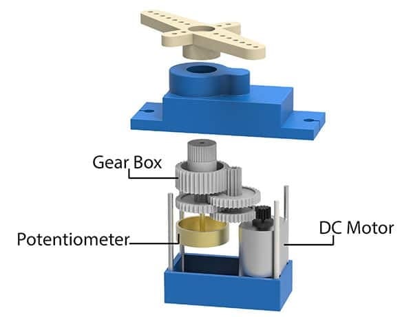
Inside a servomotor we can find a small motor, some gears, and a control circuit. The gears give additional strength to the motor and regulate its speed. When given appropriate power, the servomotor shall stay in its position. This control circuit listens for directions on where to move. If it indicates a movement to another place or position, it controls the motor. It starts the motion gears that make the connected part relocate to the indicated spot and stop there. Once the part reaches the intended position, the servomotor stops and holds it there until it's told to move again.
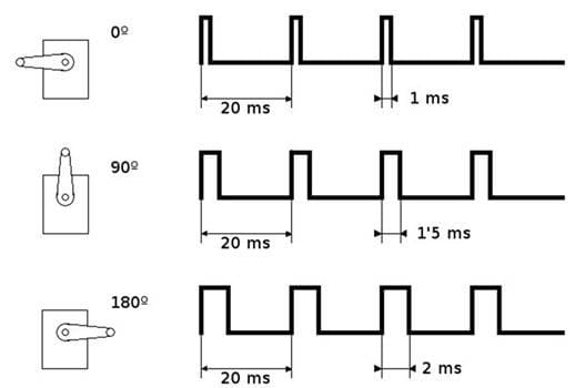
Pulse Width Modulation, or PWM for short, is how we operate the servomotor. Assume you have an on/off light switch. PWM is similar to rapidly flipping on and off and adjusting the duration of a switch. Where servomotors move is determined by the PWM signal's "on" time. The length of time the motor is "on" determines how long it will spin in one direction. You may accurately control the location of the servomotor itself by varying this "on" time.
Using PWM to control a servomotor is a clever way to give instructions to the motor using a simple electrical signal. The microcontroller sends PWM signals that have different "on" times, and so the servomotor follows them until it moves and eventually stays in the position corresponding to the signal. In fact, that arrangement is what makes servomotors useful for so many different applications, as they allow very precise control with just a few electronic components.
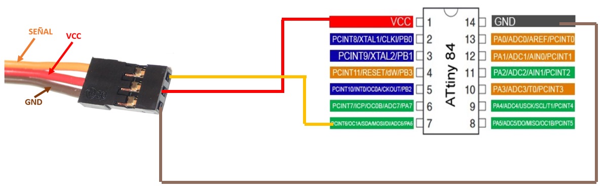
Just like the OLED display, thanks to the Arduino IDE, using a servomotor is easier thanks to the libraries availables on the software. Just to mention it, thanks to some university subjects, I have used servomotors without any library, and it was time-consuming and tedious, because I needed to use an oscilloscope to view the PWM signal of the microcontroller. For this week practice, I used the same Attiny44 board to control the servomotor. To connect the servomotor with the Attiny44, I only used the VCC and Ground pins and a PWM pin. In this case, I didn't have any trouble with the microcontroller or uploading the code. In the image below, I pointed the PWM pins of the Attiny44.
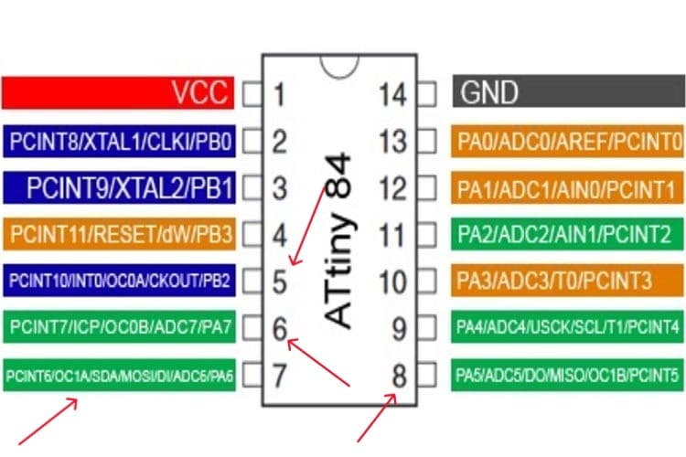
In my case, I used the seventh pin of the Attiny44 to use the first timer. The image below shows how I connected the Attiny to the servomotor:
Now that the servomotor is connected to the Attiny44, it is time to program it. I programmed my Attiny44 using an Arduino as ISP. You can see how to use an Arduino as a programmer on my website, to be more specific, right here. This is the explanation of the code used this week:
#include

Servo myservo;
int angulo;
void setup(){
  myservo.attach(6);
}
void loop() {

  angulo= 0;
  myservo.write(angulo);
  delay(2000);

  angulo= 90;
  myservo.write(angulo);
  delay(2000);
...
}
It is important to add that if you are using your USB port for the PCB power, you should use only a few servomotors, because you can burn the port.
Here is the video of the Attiny44 working with a servomotor:
To download the codes used for this week, you can click here.