Building a FABulous desk

For my final project I will construct a collaborative desk that could be used for courses such as Fab Academy and project development or coworking.

Please check out my week 18 site for licensing info and future plans of the project. And also check my week 17 site for schedule and system integration, and for the bill of materials and other questions check my week 16 site.
Research and Inspiration
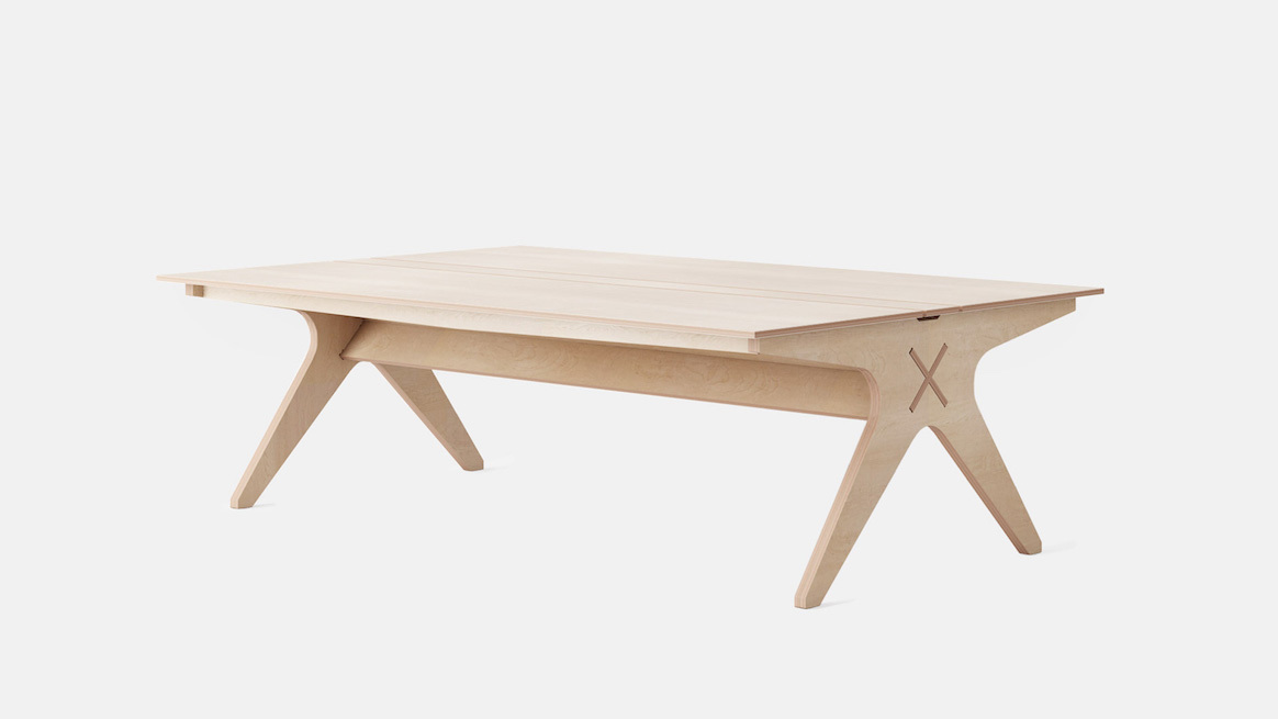
On the past summer, I helped my instructor Rafael build a collab desk for his classroom, this was a desk made by opendesk, it was a mess and in the end it needed screws to be assembled. But I learned a lot from this for example to use the CNC machine. So when I joined the course I wanted to build something similar and improve in some areas I saw fit to.
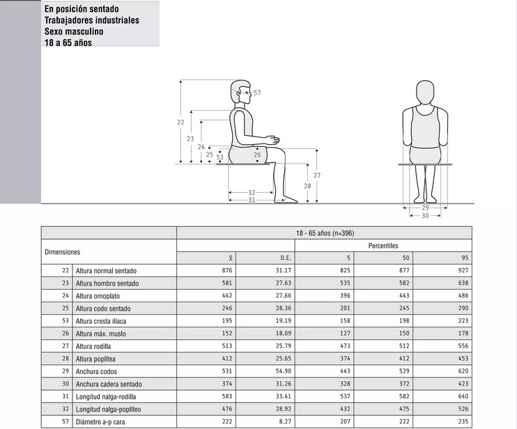
In order to make the desk I made some research on ergonomy, I first used the meassurements of the desk and made them fit the ergonomics of this book. Mainly I focused on 18-65 age gap for male workers sitting, for the meassurments I stayed with the percentil 50.
Sketching
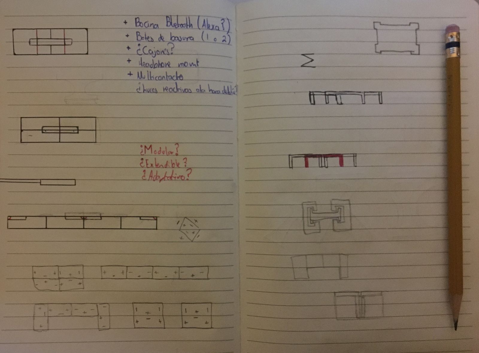
Here are the first sketches I made on a notebook, I finally settled on how the unions for the modules will be and the shapes of the legs and table, I only need to get accurate meassurements to start designing it.

In the third week which was about laser cutting, as part from the assignment I modeled my final project in scale and cutted it. I cutted it on a 1:10 scale to check if the legs I designed were able to support the weight of the table and if it didn't tilt, which it didn't so I will use that desgin for the legs on the table I just had to adjust the distance between the legs.
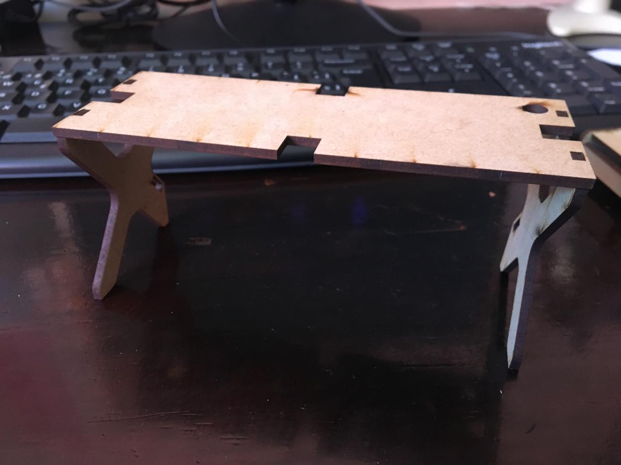
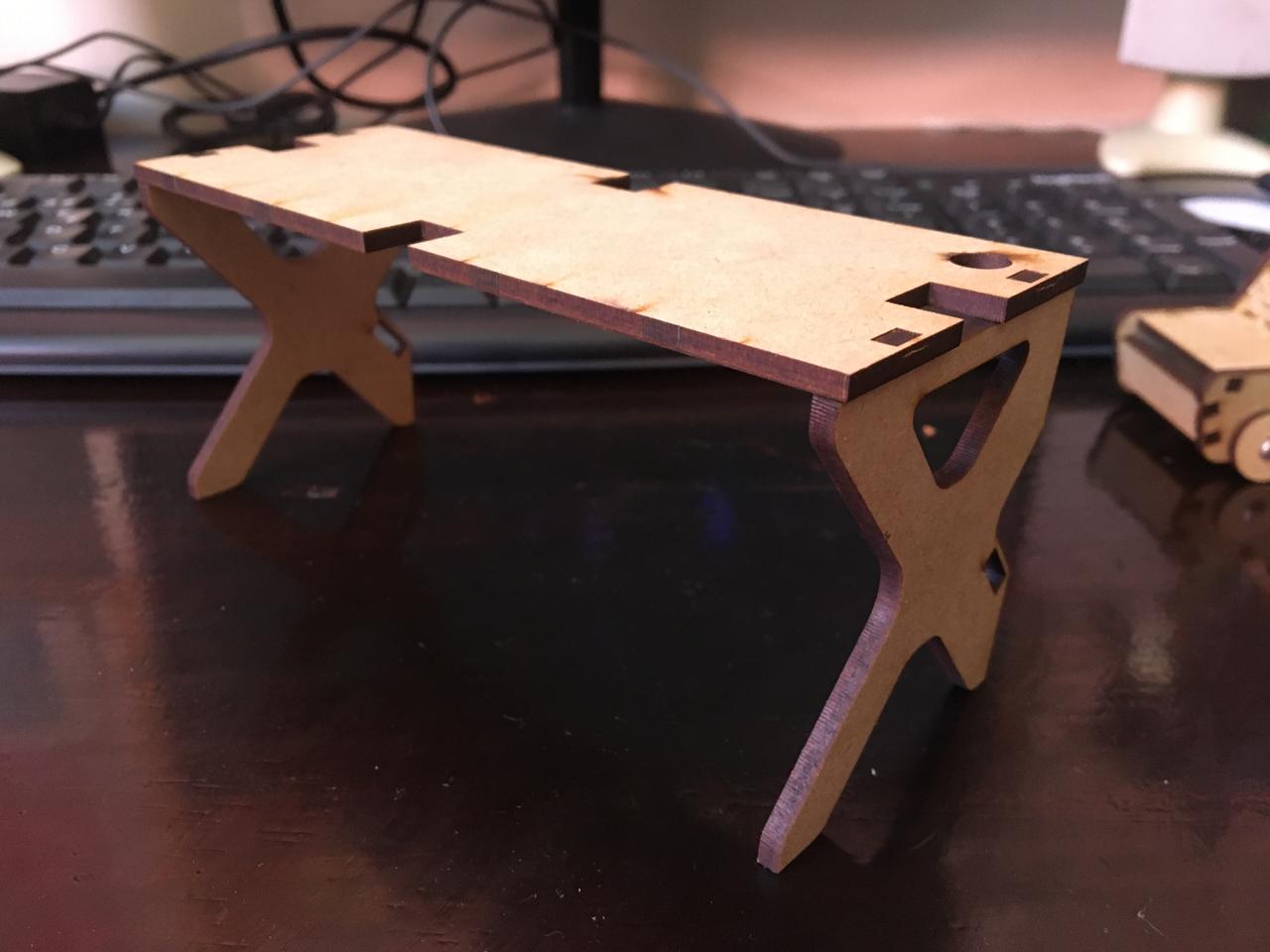
I needed to do some adjustments but it was a good start, because making scaled models can help us solve problems before they are presented on the real deal. One of the improvements I made after the model was to include a pegboard based on the IKEA Skadis.
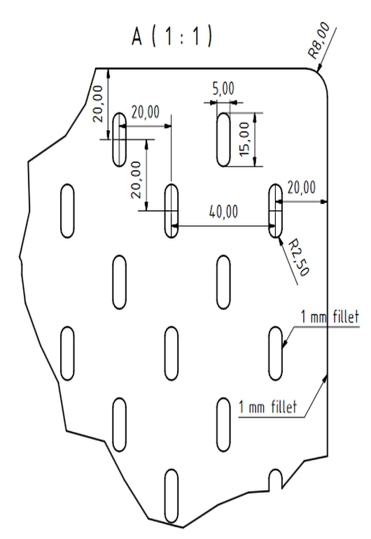
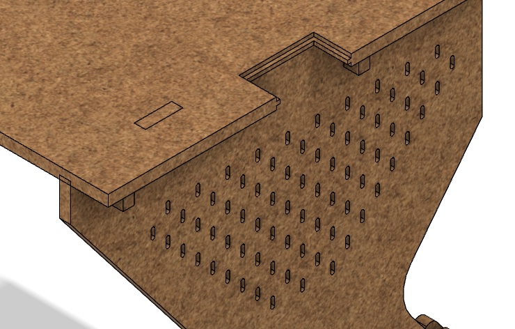
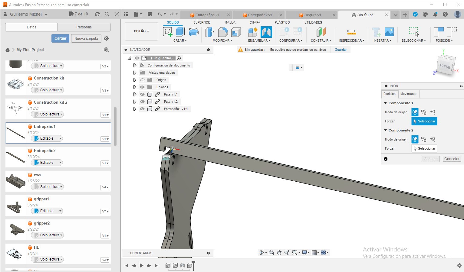
I designed the rest of the parts and made ensambled it on Fusion to check everything fitted correctly, I liked using Fusion because of the animation and rendering tools, and also because since all the models are saved on the cloud I can work from my laptop and my pc.
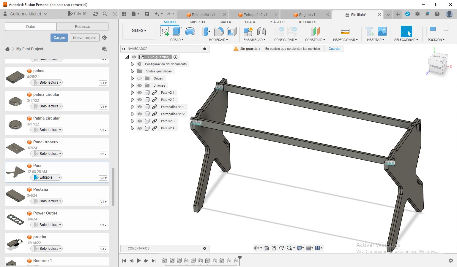
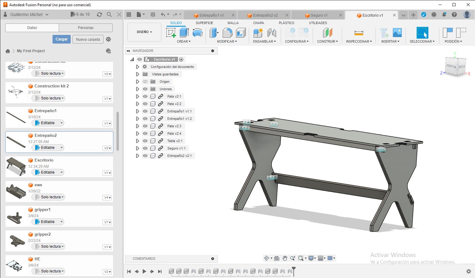
This are all the necesary pieces to assemble one desk, all of this fit on one 122x244 board, as many desks as needed can be made.
Desk CNC routing and building
I exported all my designs to .DXF and imported them on Vcarve, I made everything fit properly on one 122x244 board.

I exported the file for the ASIA CNC, and cut the board there.
Afterwards I sanded all the pieces and assembled it, one desk takes about 2:00 - 2:30 hours to cut at 70-100%
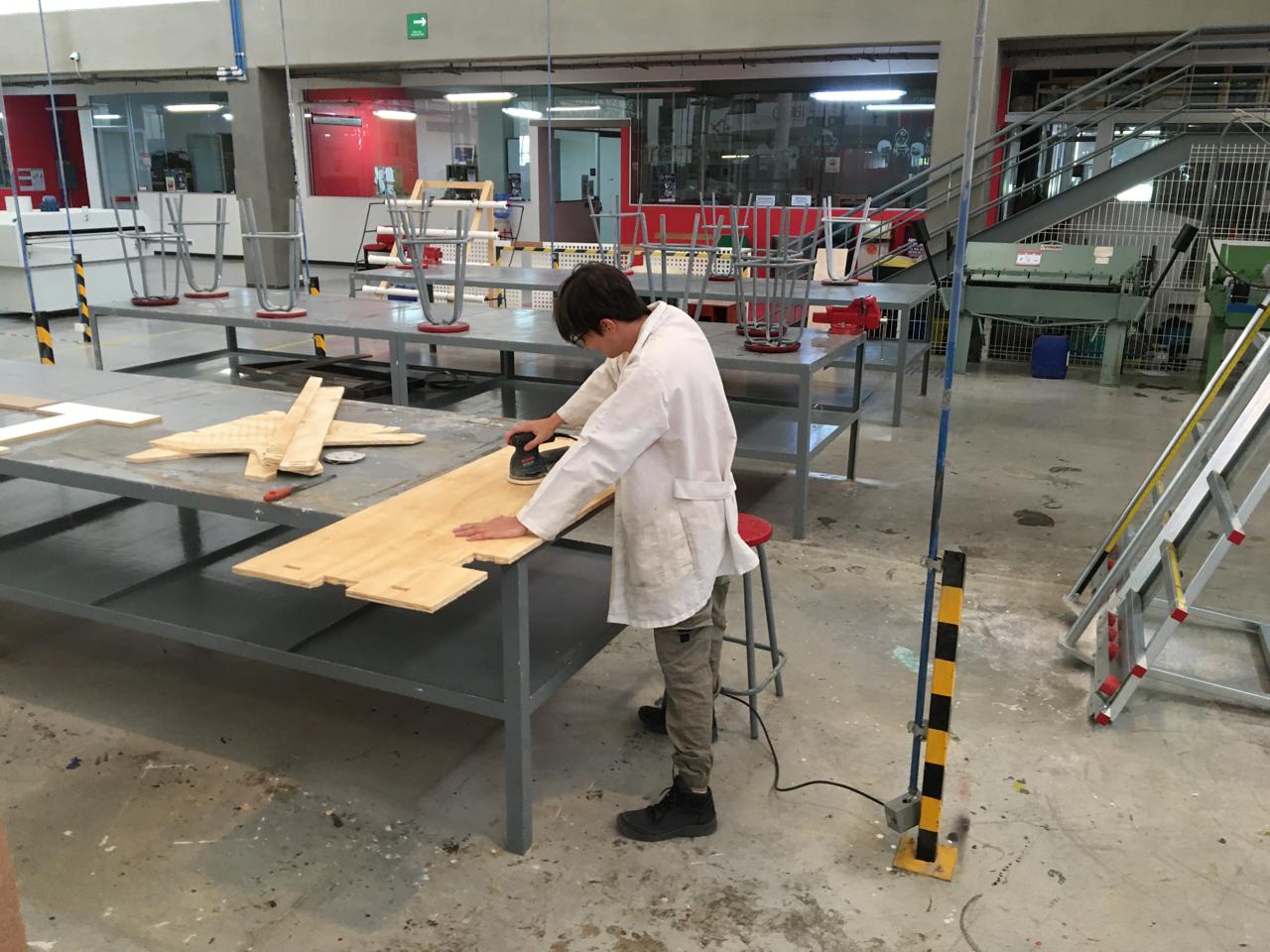
Then we can assamble the desk, it takes about 1-2 minutes to put it together you just need a rubber hammer.
Here you can download all the files to build your desk, I would advice you make your own G-code but here are the codes for the ASIA and Mach machines
Power outlets and AC input
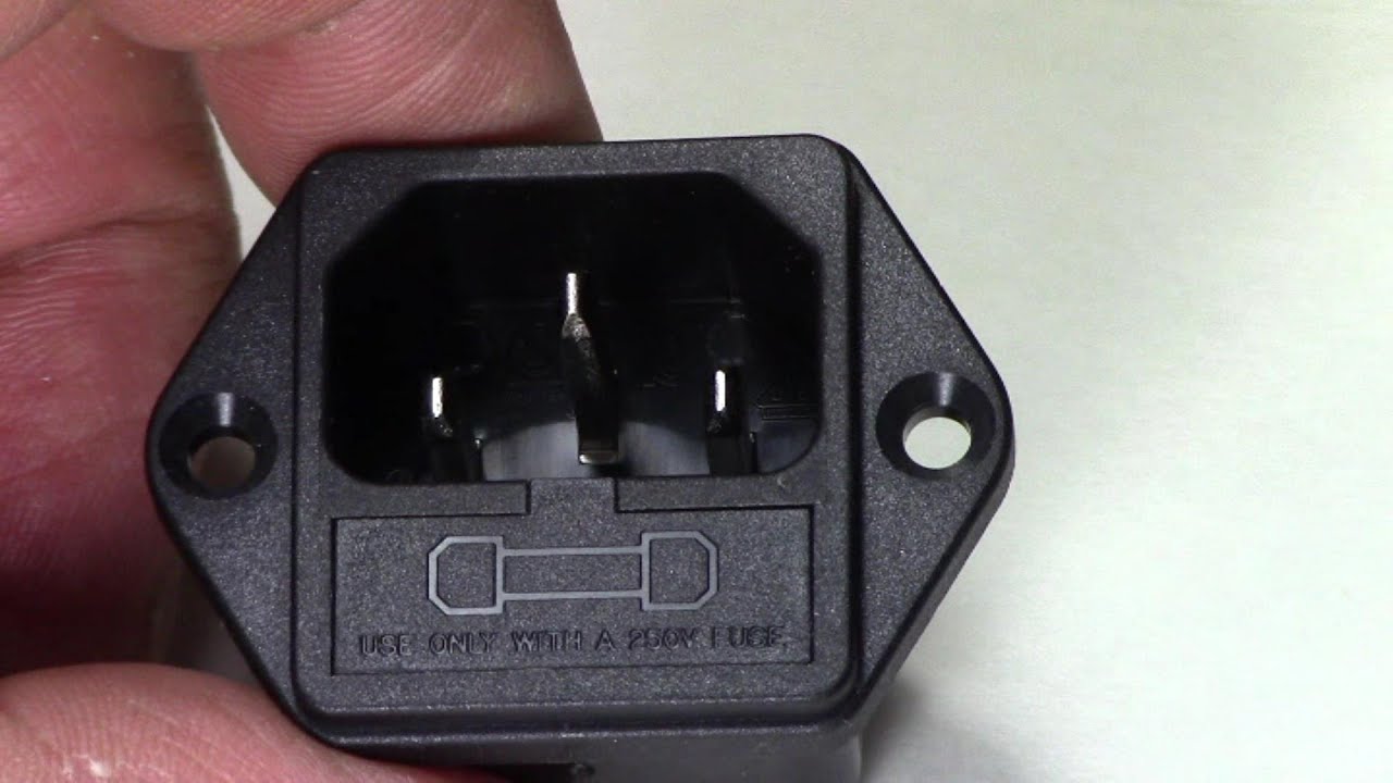
In here we combine electronics and 3d printing. First I designed the case for the current input, I used a switch and an AC input socket with a 250 V fuse
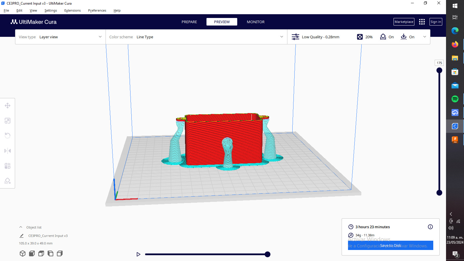
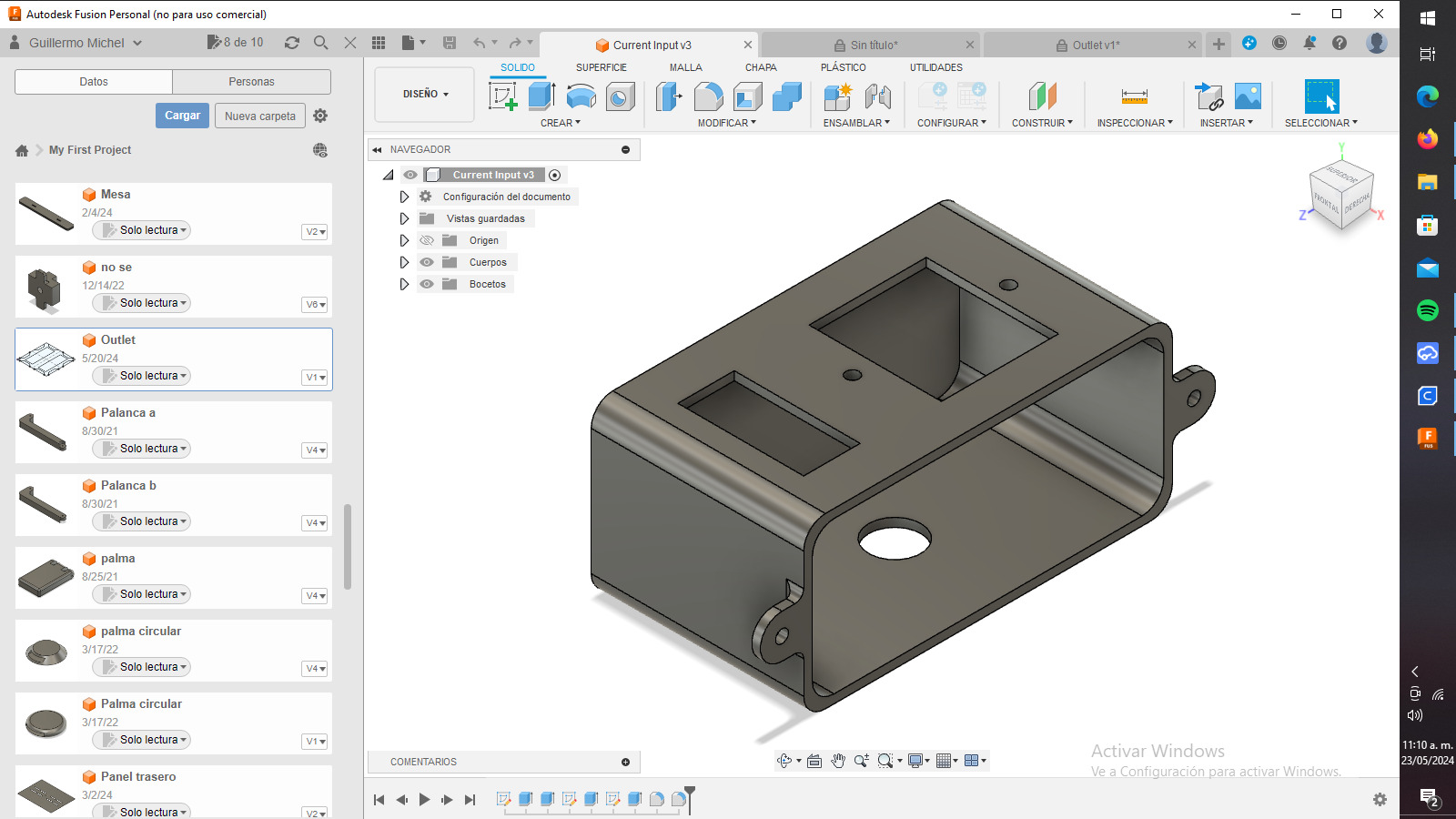
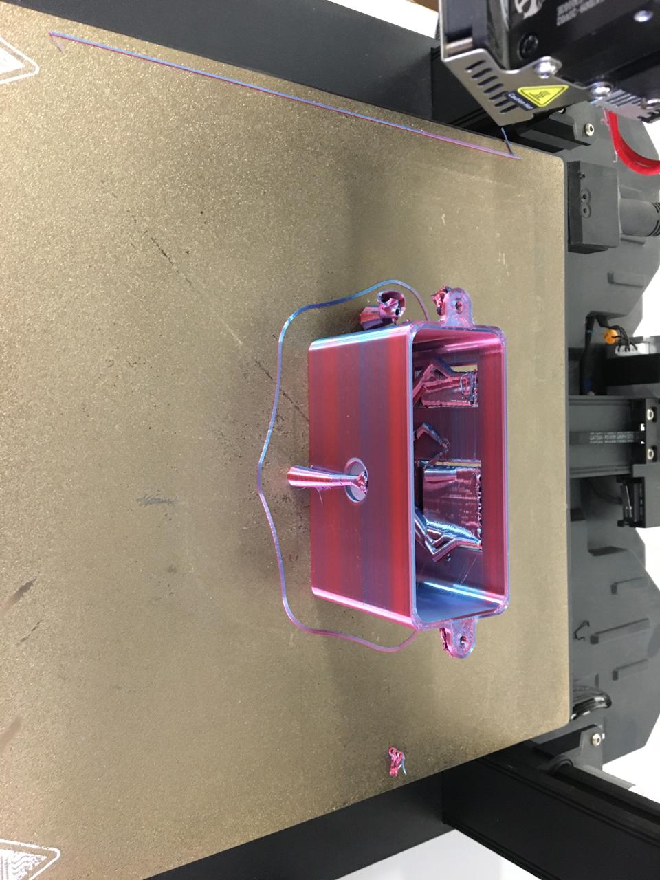
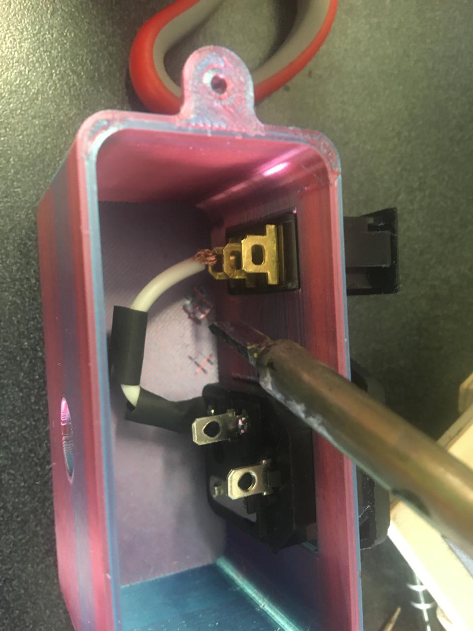
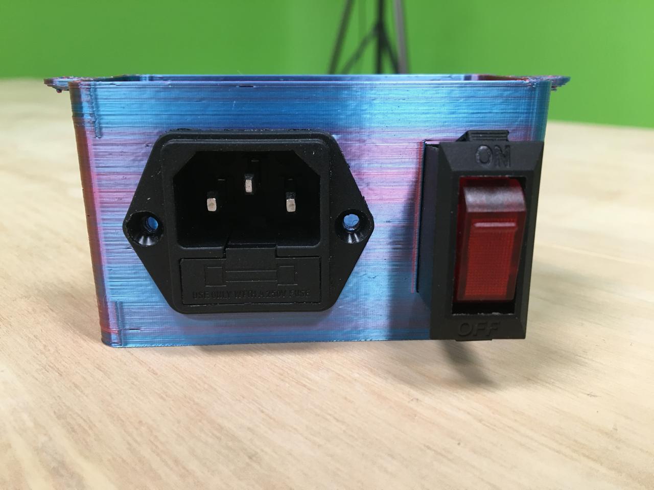
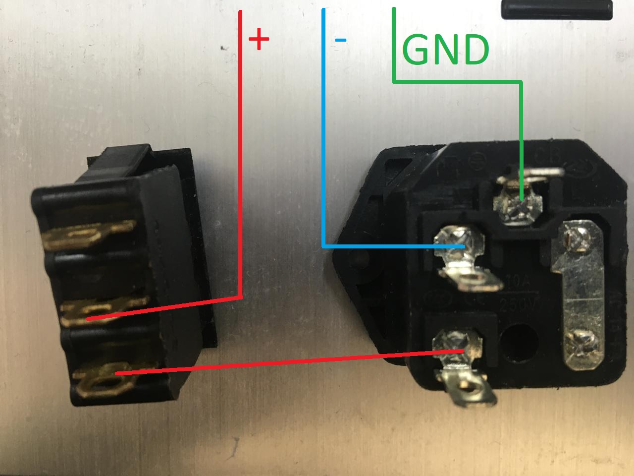
I 3d printed it and solder the components like this, the switch is added for security.
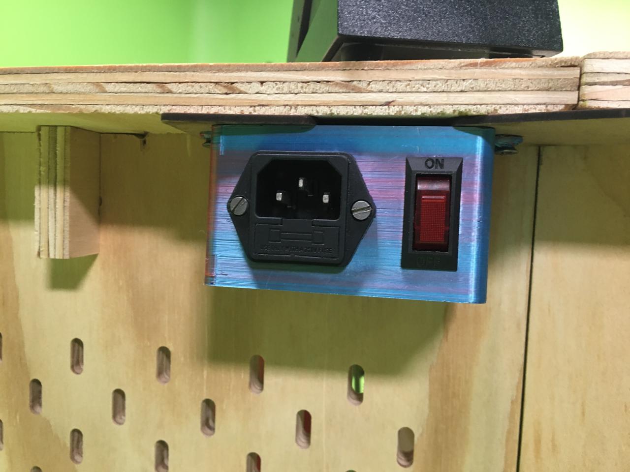
Finally using screws I mounted it to the desk
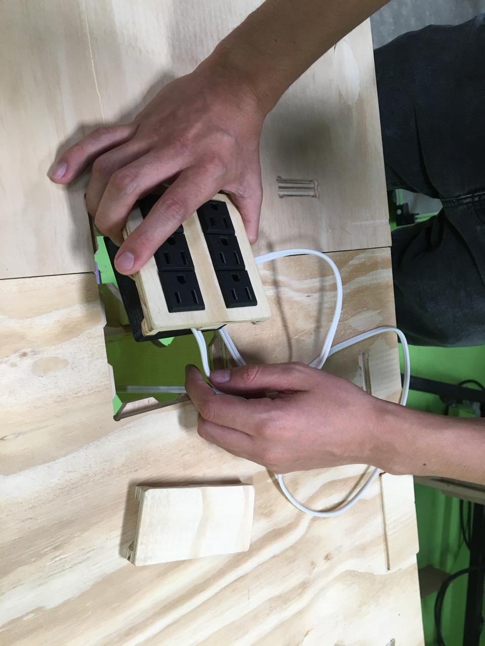
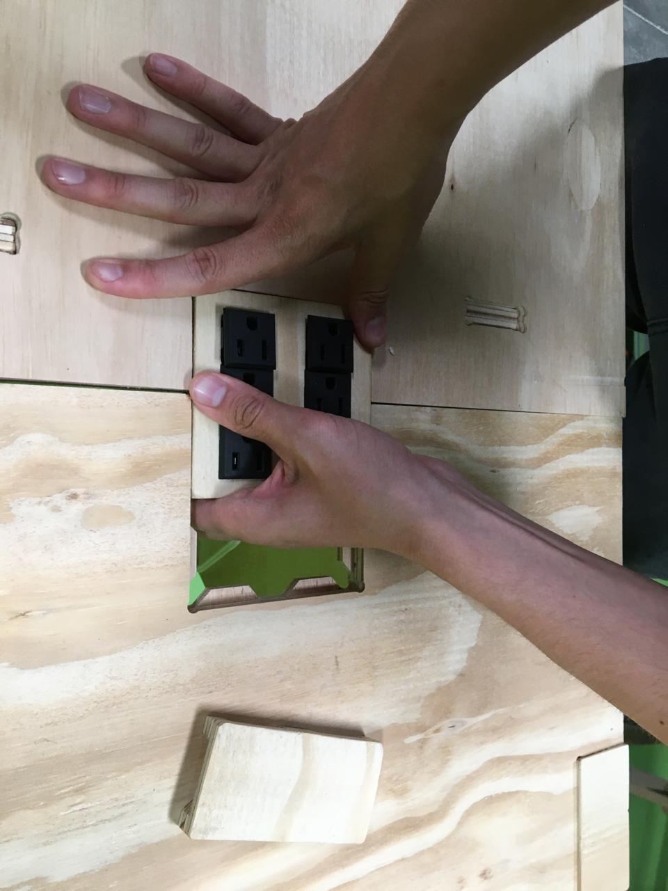
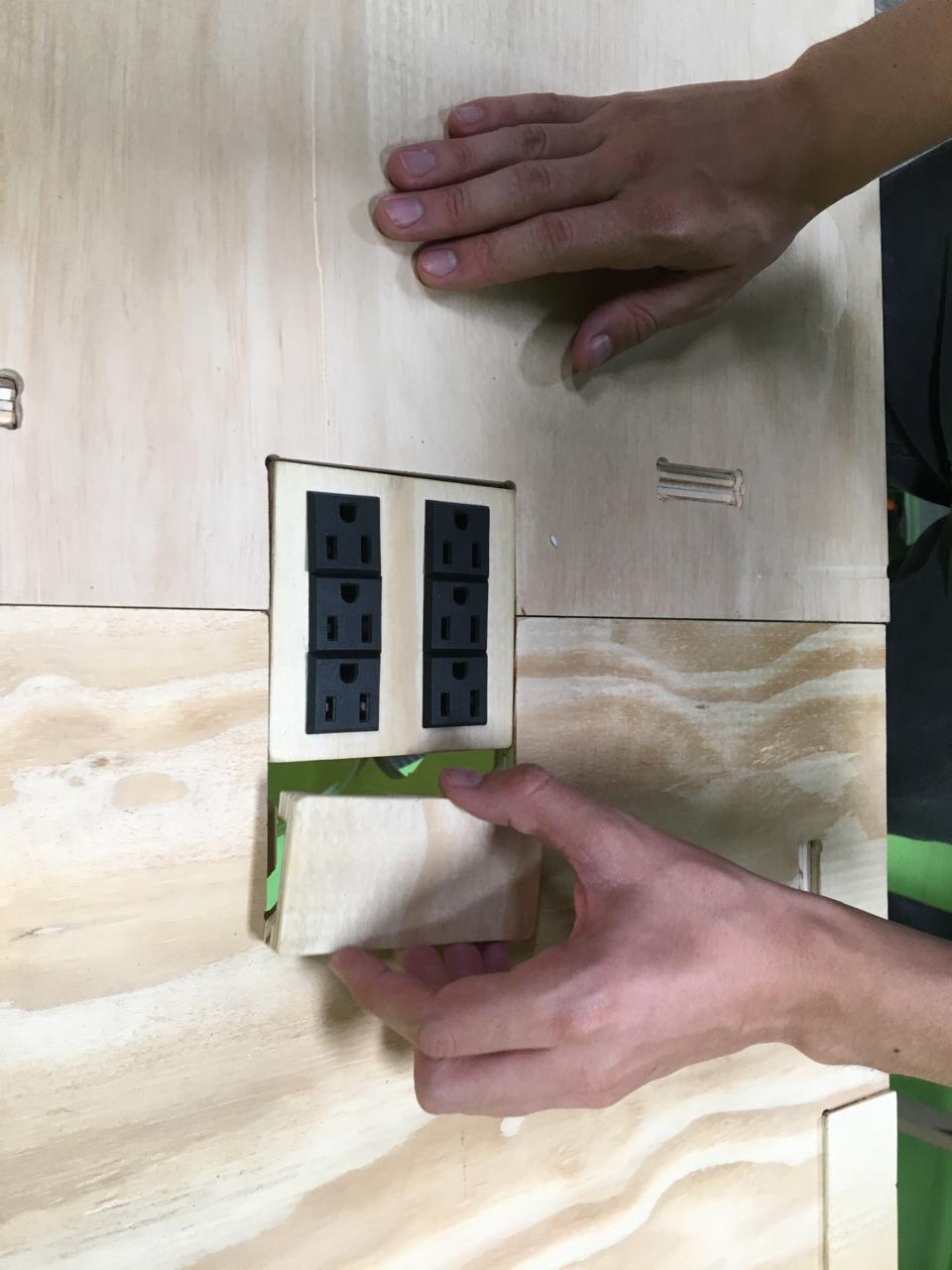
Then I went for the outputs, one of the routed pieces that works as a module can fit this three phase outlets, the model used is: TECX SO-11-1. I followed the following wiring for the power outlets.
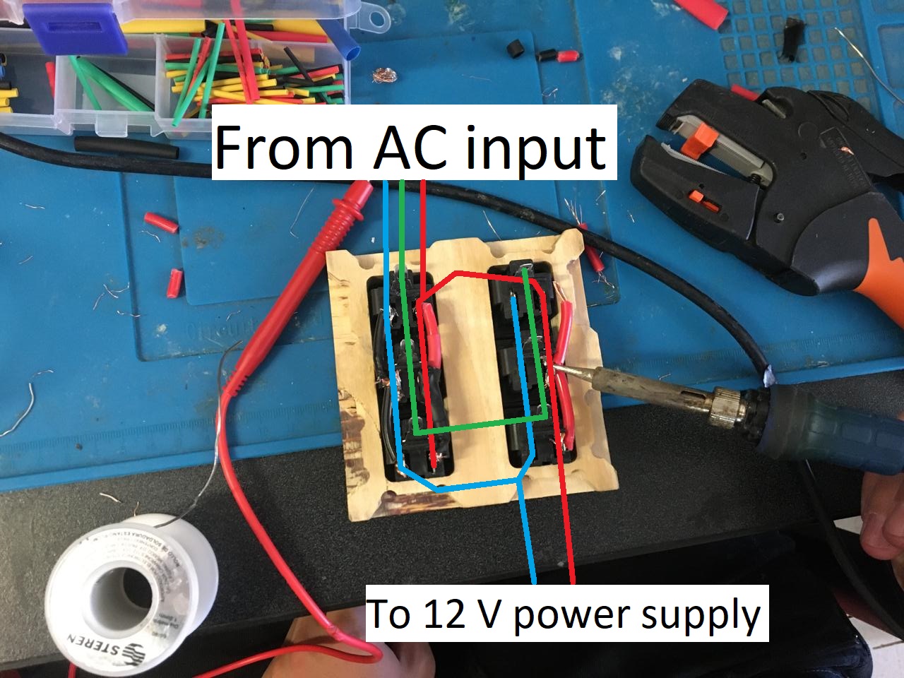
I 3d printed this case for the electronics, it has two holes, one for the three phase cable input and the other for the output to the 12V regulator.
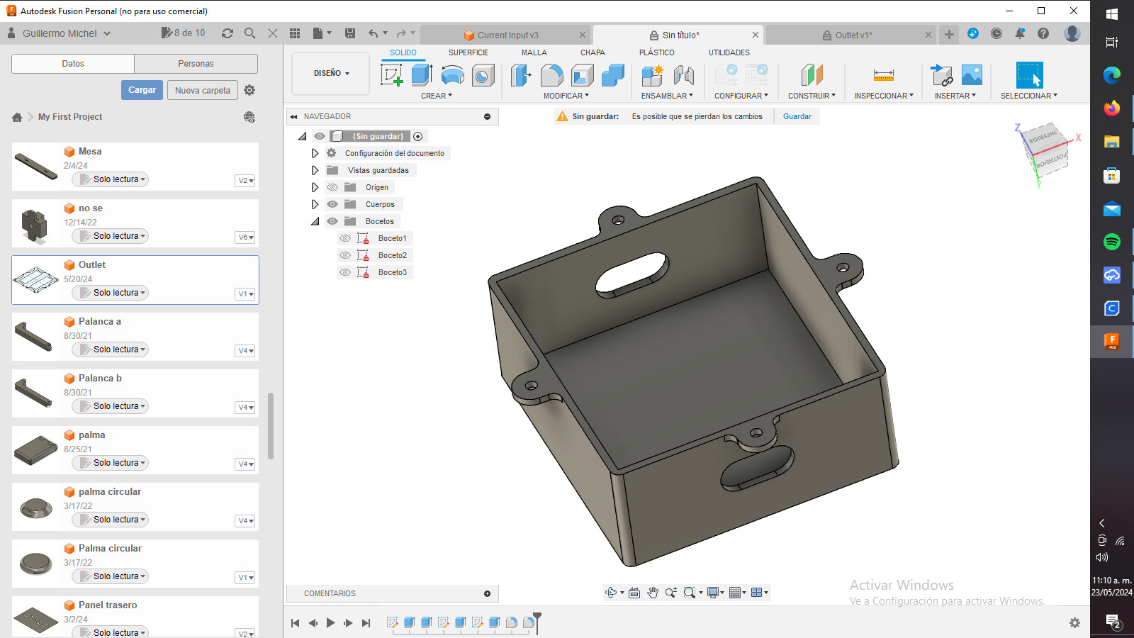
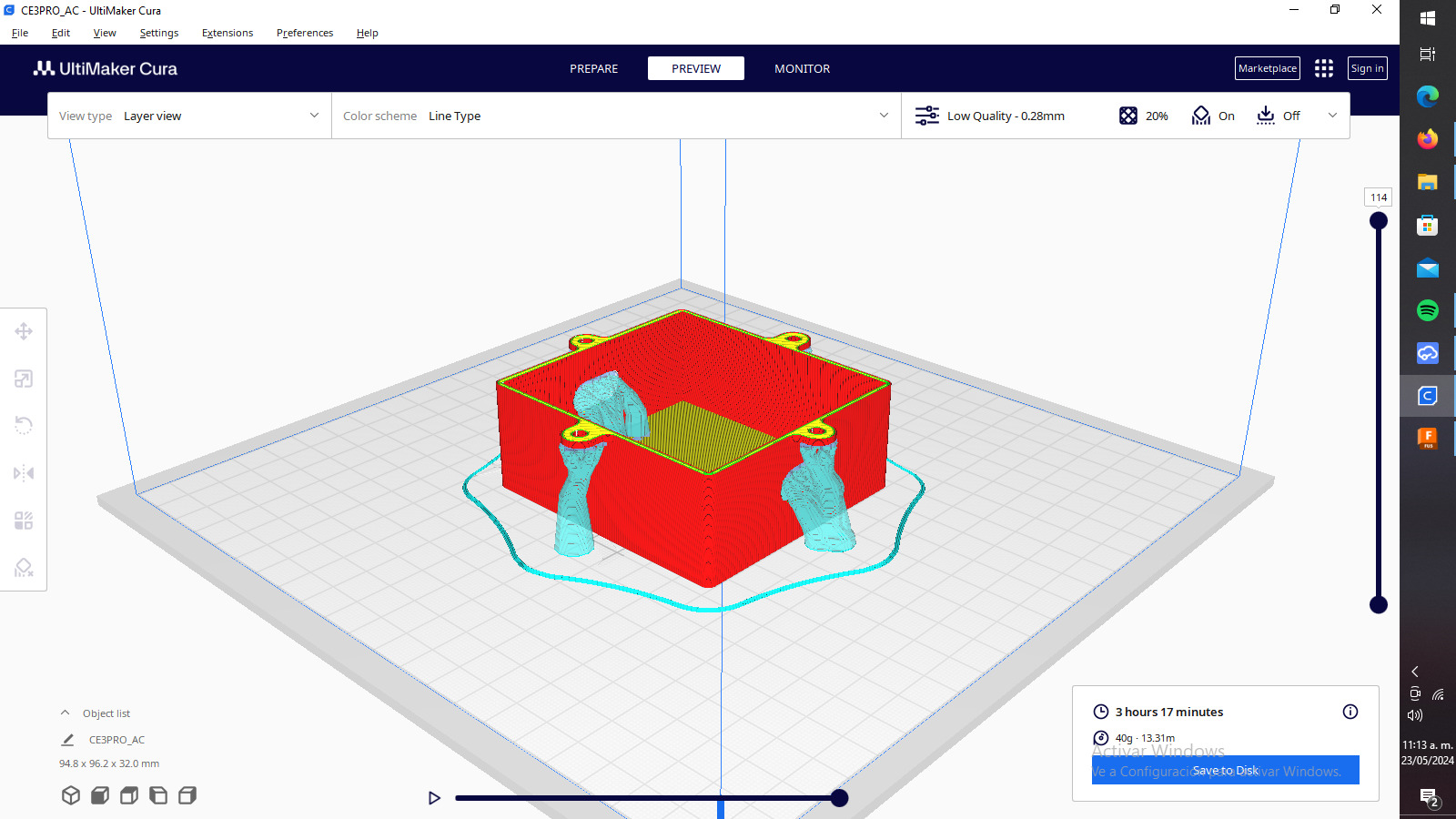
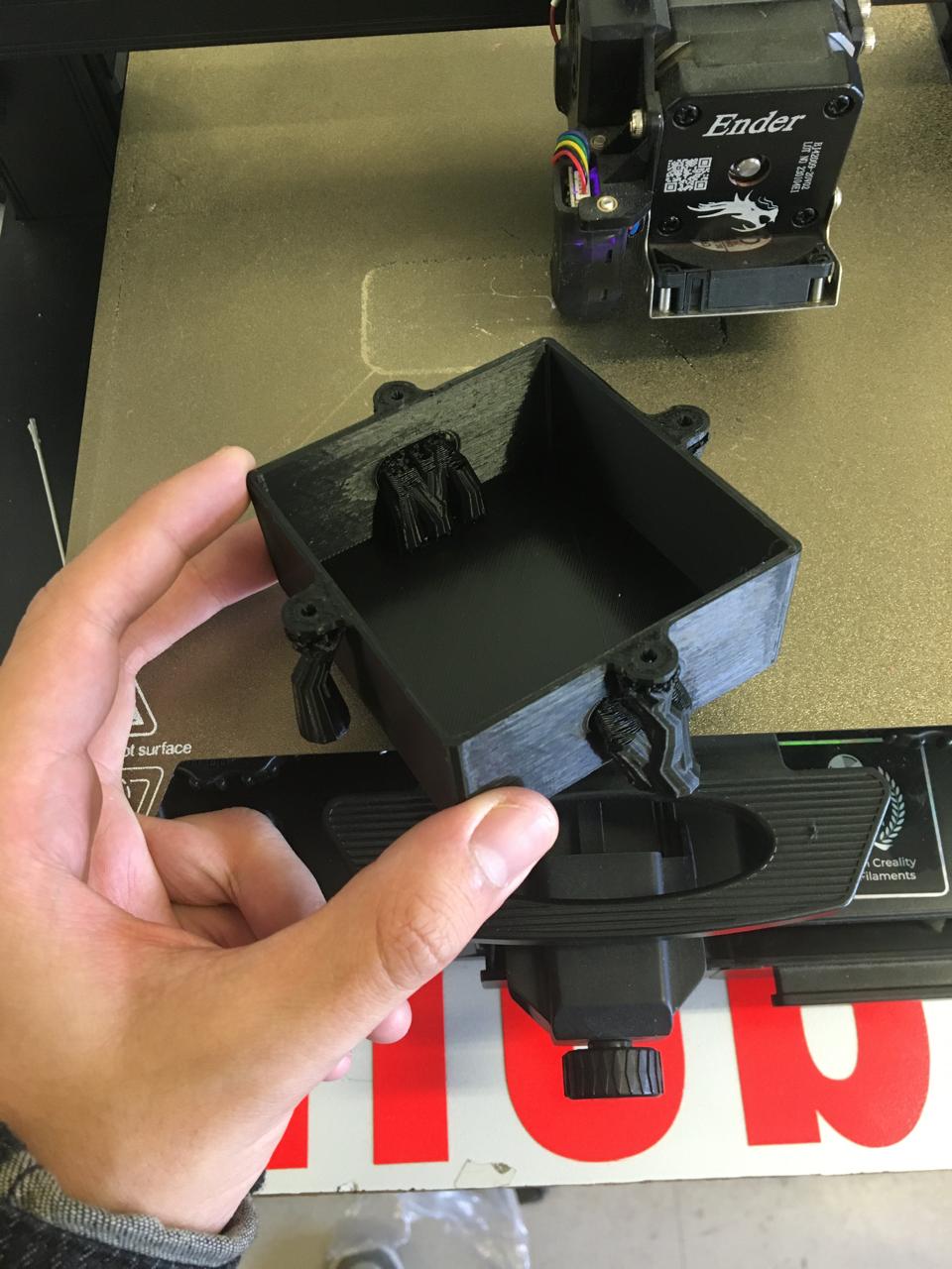
I made a knot on the cable so if it's pulled it doesnt rip apart.
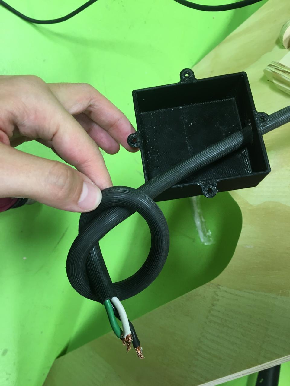
I moved onto soldering and tested continuity with a multimeter, this is really important here because if there is a short and you plug it, it can damage your AC installation.
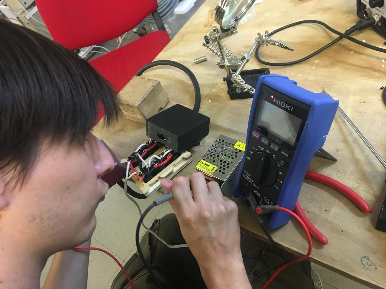
Finally I put everything together in the desk. I just screwed some screws on the holes so it stays put. I used this same cover for the electronics part.
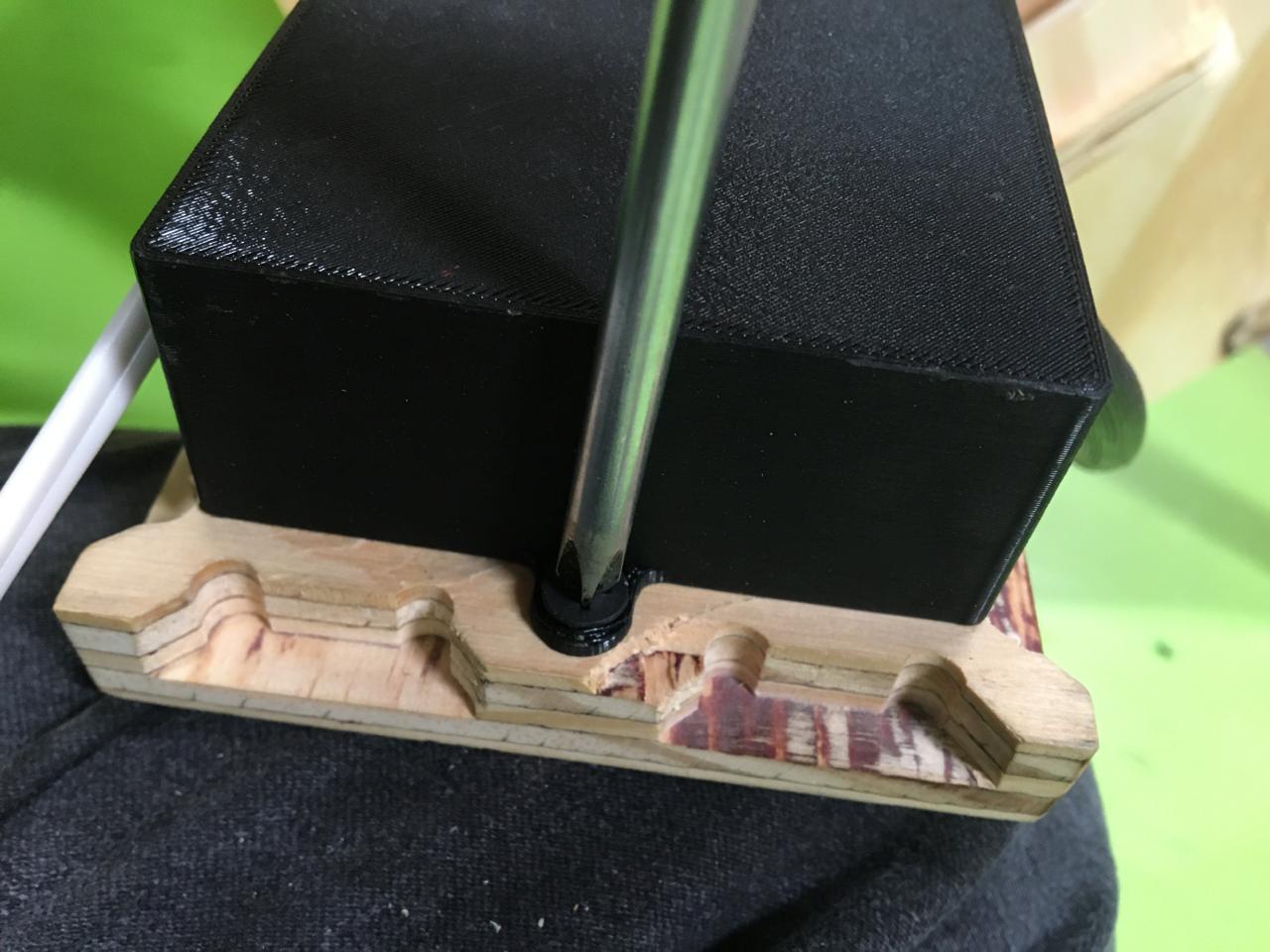
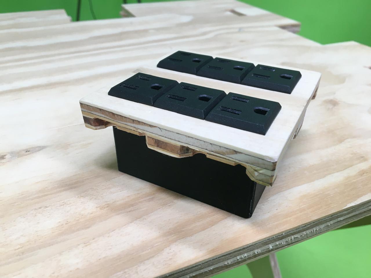
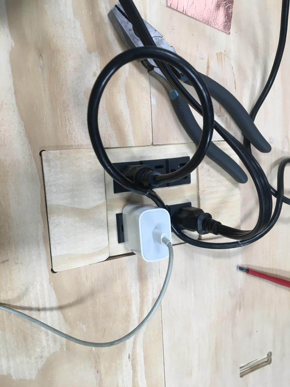
I followed the next diagram for the 12V needed for the LED strip and the 5V for the MCU
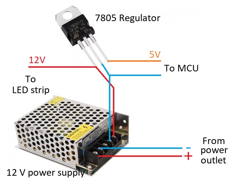
3d printables and output module
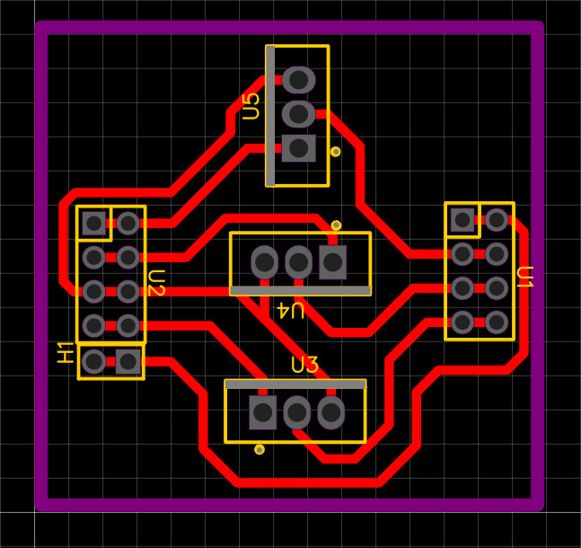
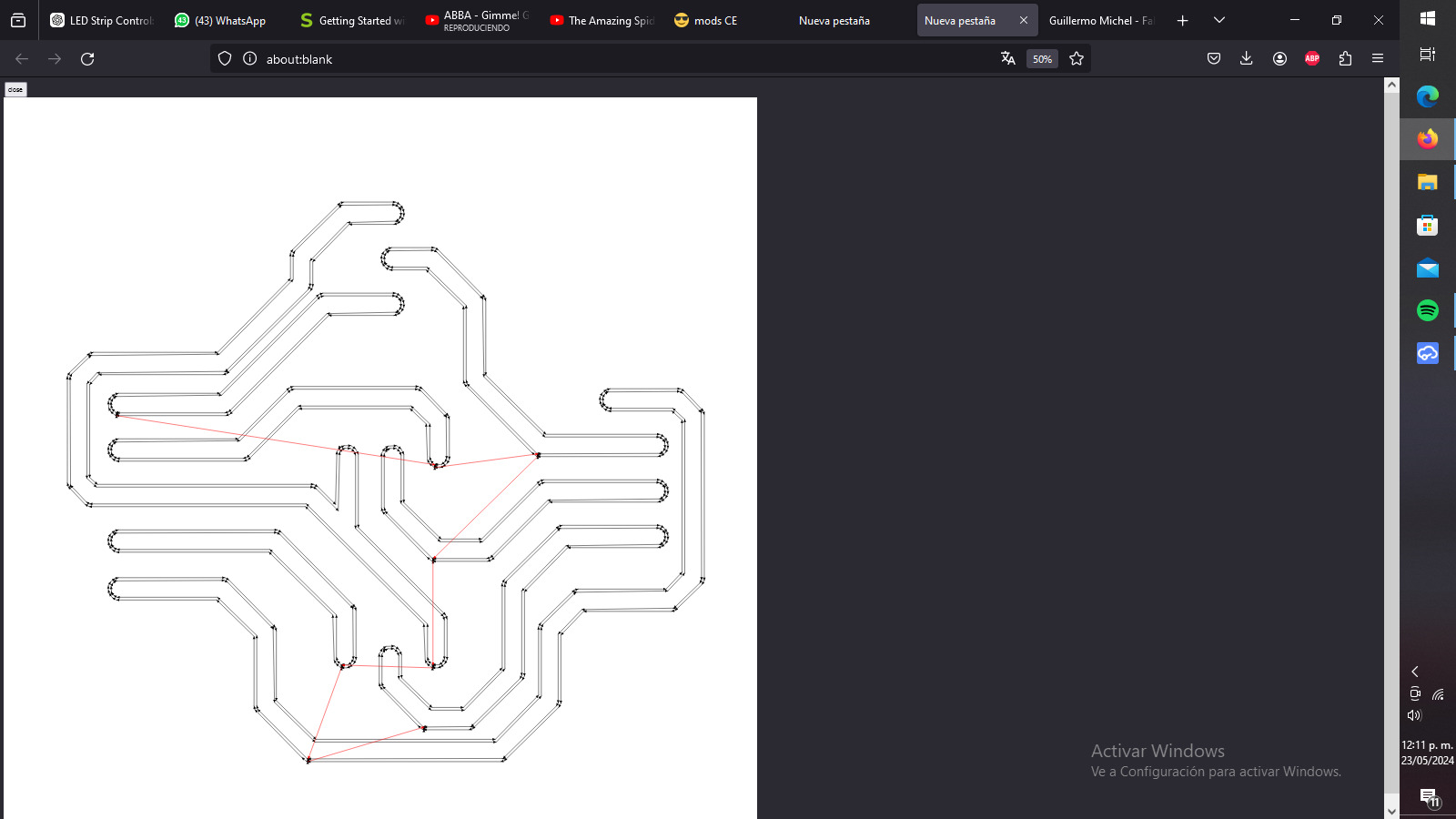
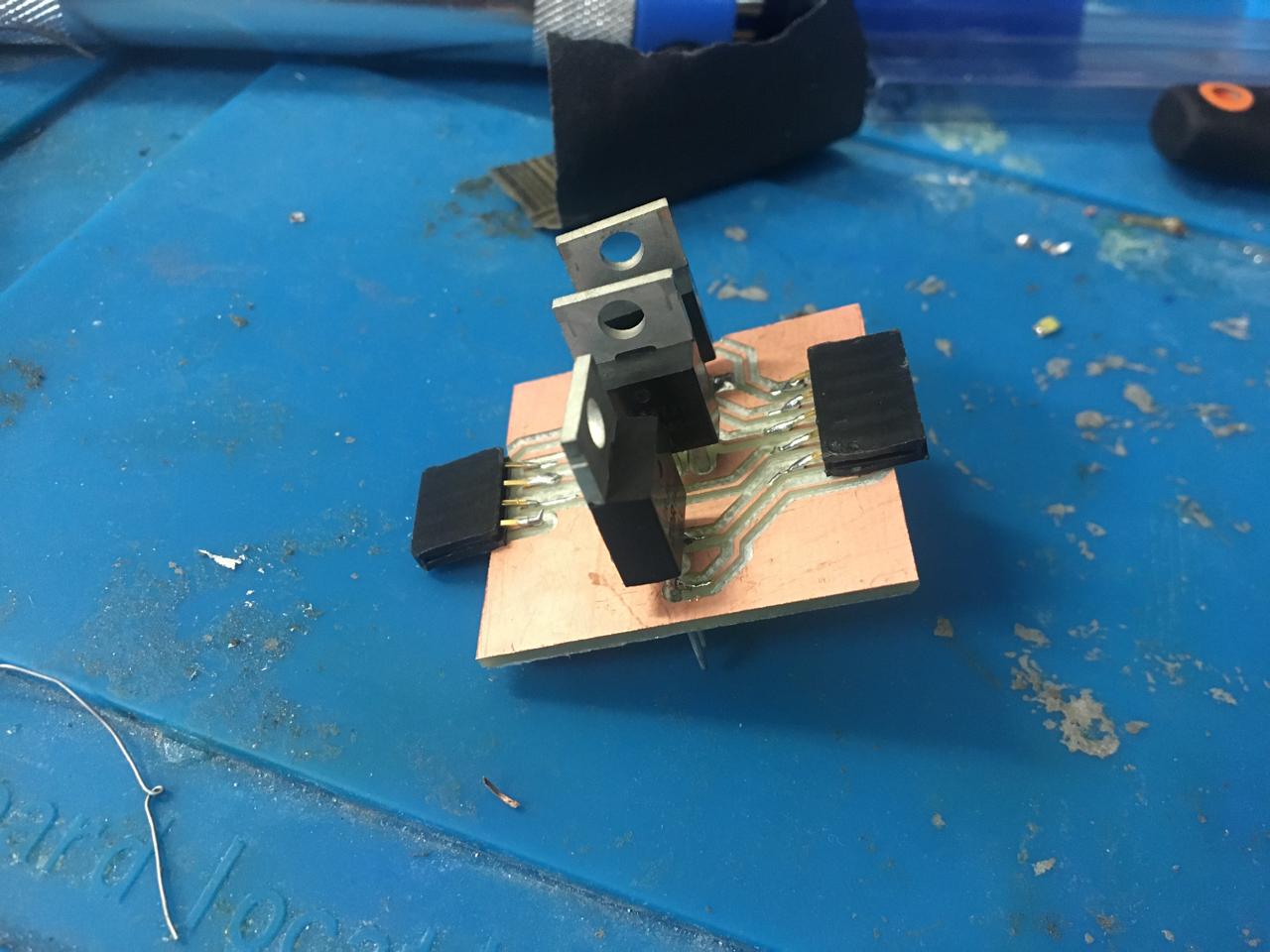
I made 3 boards, one is the microcontroller unit (mcu), then we have an amplifier for the speaker, and we have the RGB mosfets, this ones keep the signal stable from the MCU to the RGB strip.
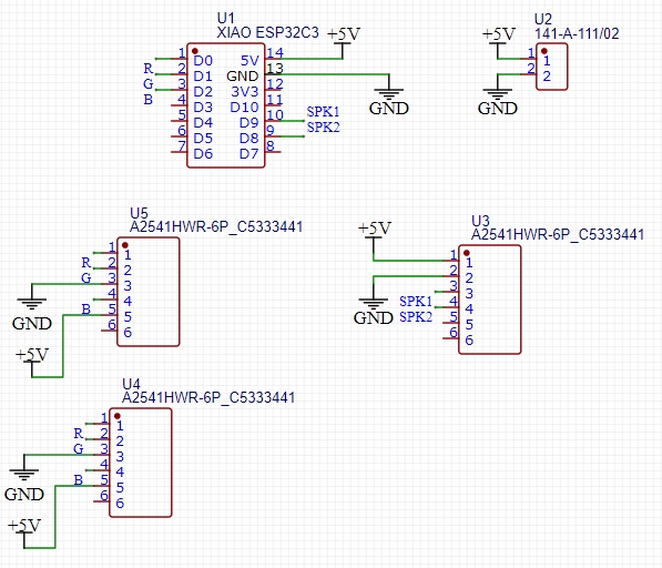
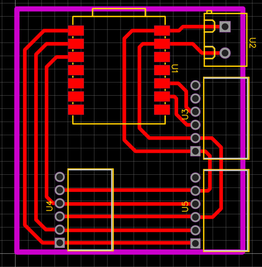
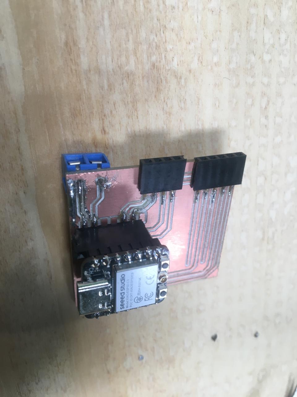
The MCU needs one XIAO, a luster terminal and some pinheaders. I made so two speakers and two LED strips can be plugged.
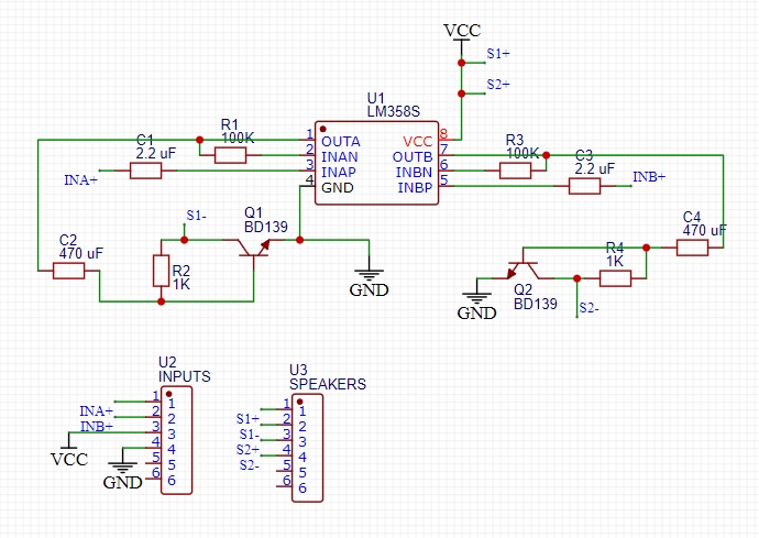
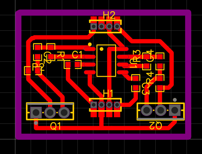
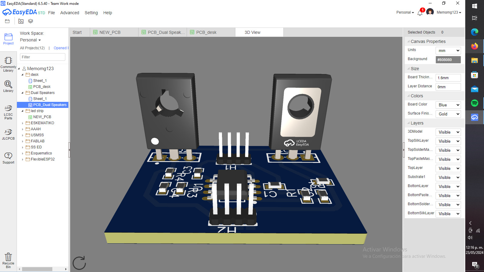

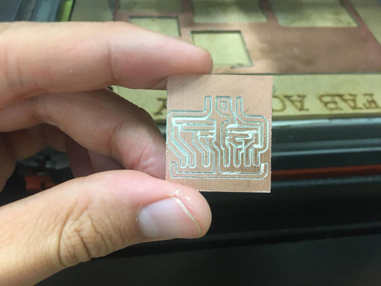
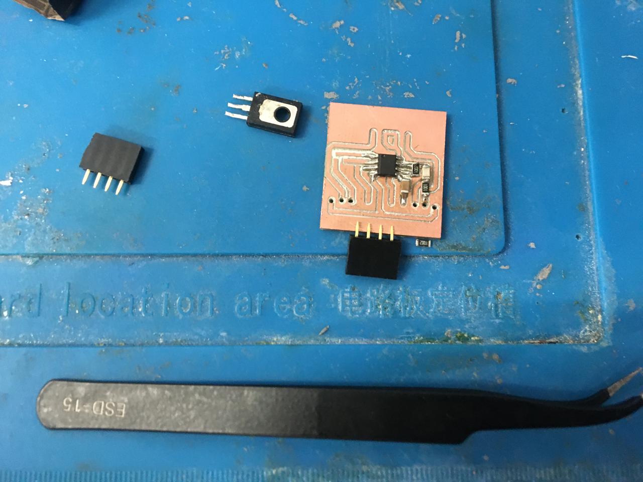
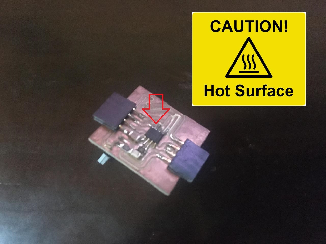

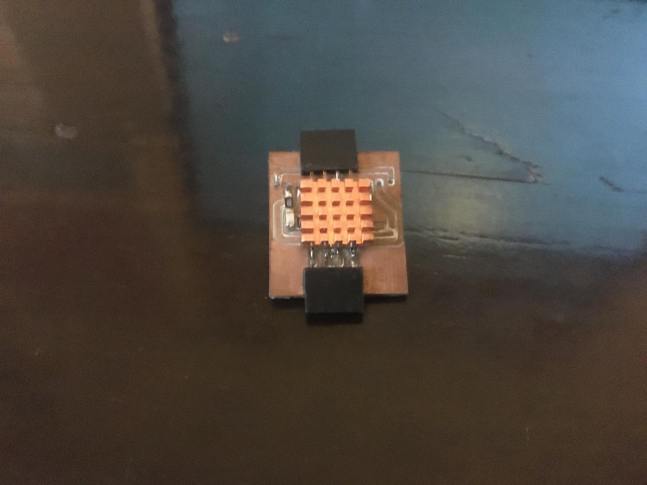
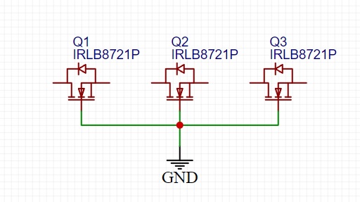
Finally this are the board with MOSFETs for the RGB, this one is not really that necessary but it makes the led strip look a bit better.
Electronics
Lamp with speaker
This is the rocky part of the project, the lamp works great, I made this 3d printed base that can press fit into one of the wood modules, and hold a LED strip and a speaker, the speaker does not work as intended, first I tried using a XIAO-ESP32-C3 to mak a bluetooth speaker but there are no libraries for audio transmission and making them will take a lot of time, then I intended to use the XIAO RP2040 as a speaker through serial, I got it to work only once (should have recorded it) but when I tried to test it again, it appeared to be locked (maybe because of the code messing with internal pins) so it stopped working. I switched the XIAO and what can be done is play sounds, In order to improve this I must switch to the ESP32 microcontroller so I can make the bluetooth speaker work because there are avalilable libraries for that board.
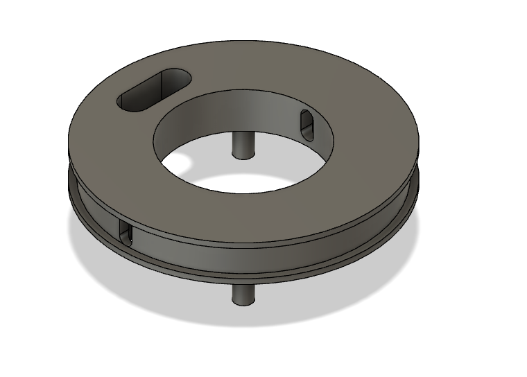
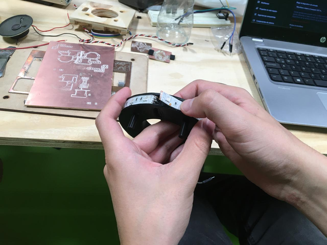
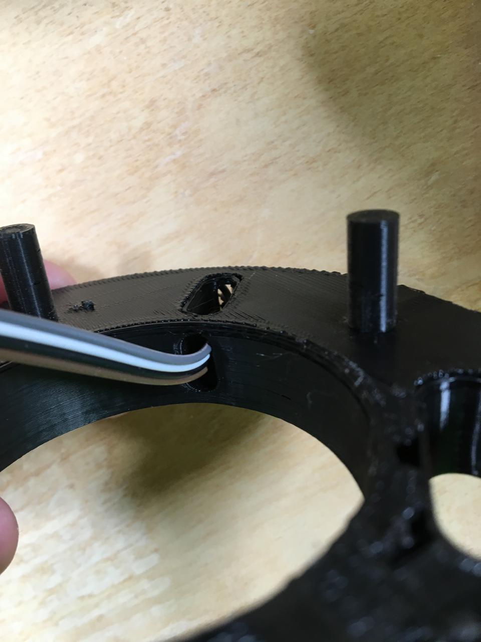
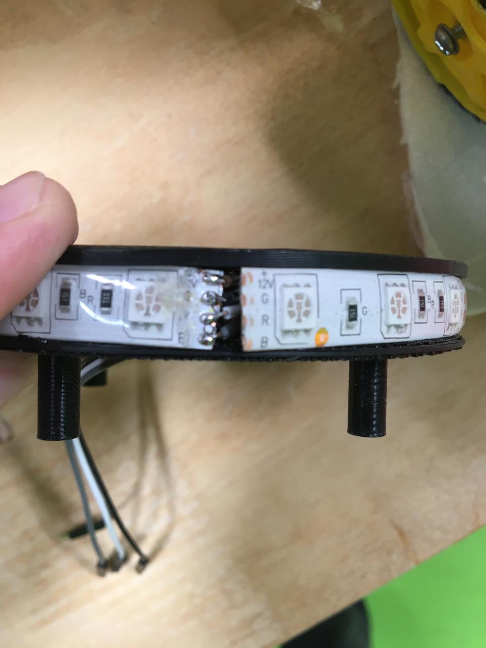
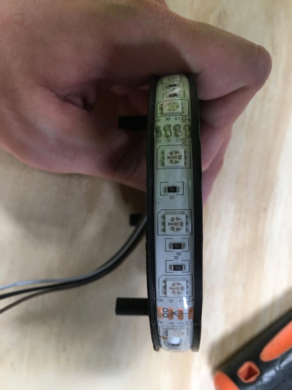

The body of the lamp was 3d printed, it's designed to press fit on the wood module, it can hold a speaker and a led strip, cable management is also included since sables can go inside the piece.
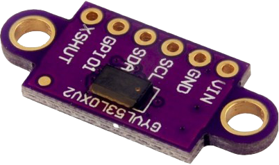
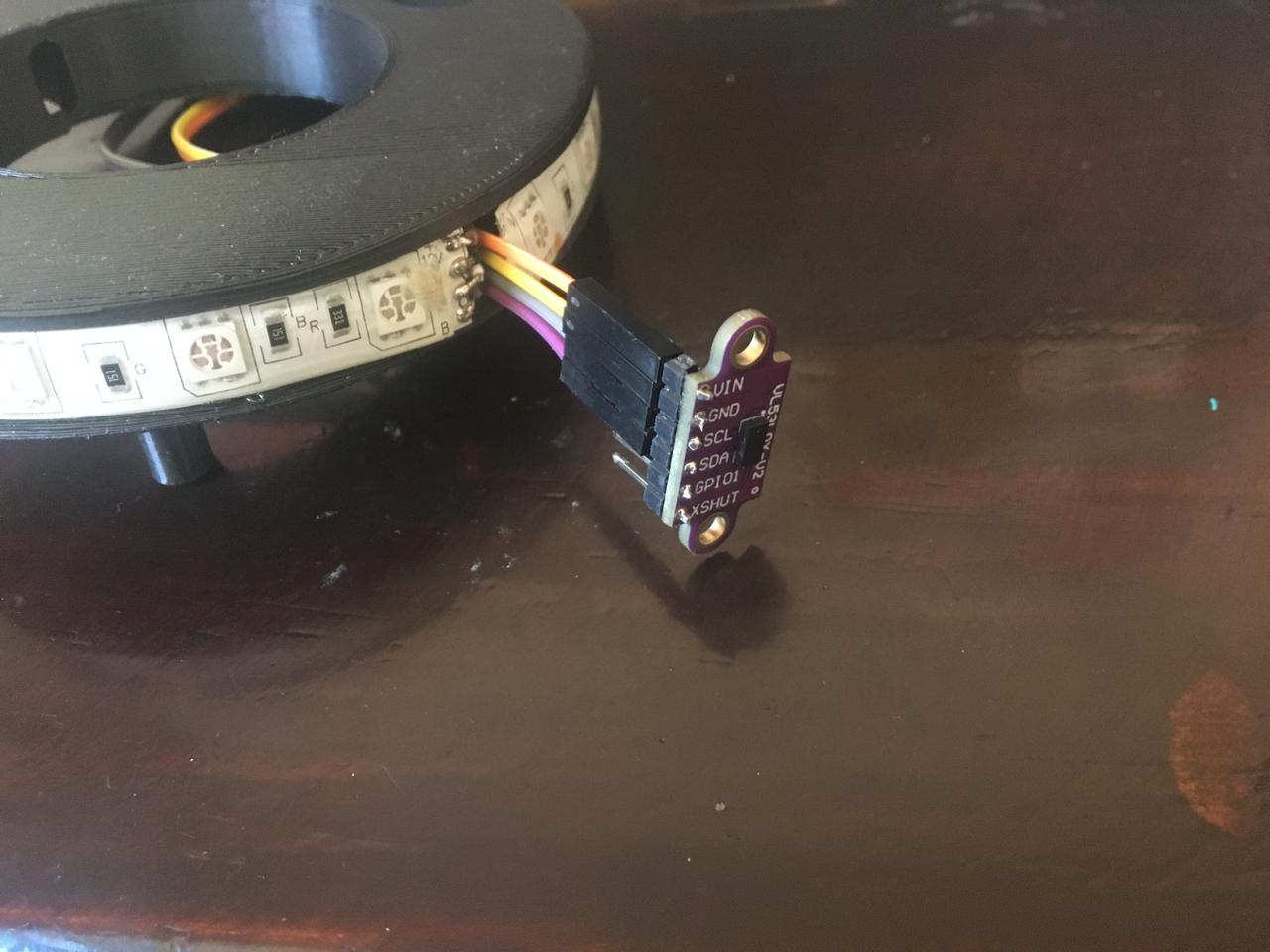
As a bit of experimentation I added a distance sensor as a dimmer for the lamp, I have programmed it to be the lowest when something is very close (2cm) and the brightest at a 20 cm so it does not become annoying when you are trying to solder something.
Lamp Files
Interface and embeded programming
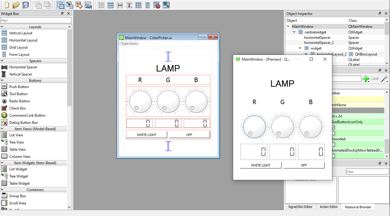
Finally we have the interface and code to control the led strip on the arduino, I didn't include the serial transmission for the speaker because after testing it, it rendered my XIAO useless
The interface is the same one I made on my week 14, you can fin the code and broader explanation there. I just implemented the MOSFETs circuit to maintain the signals better.
Interface files
Pegboard accesories
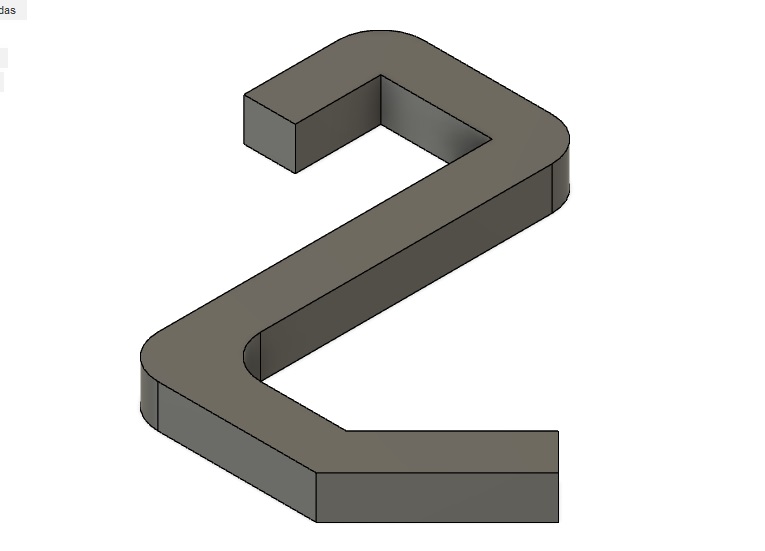


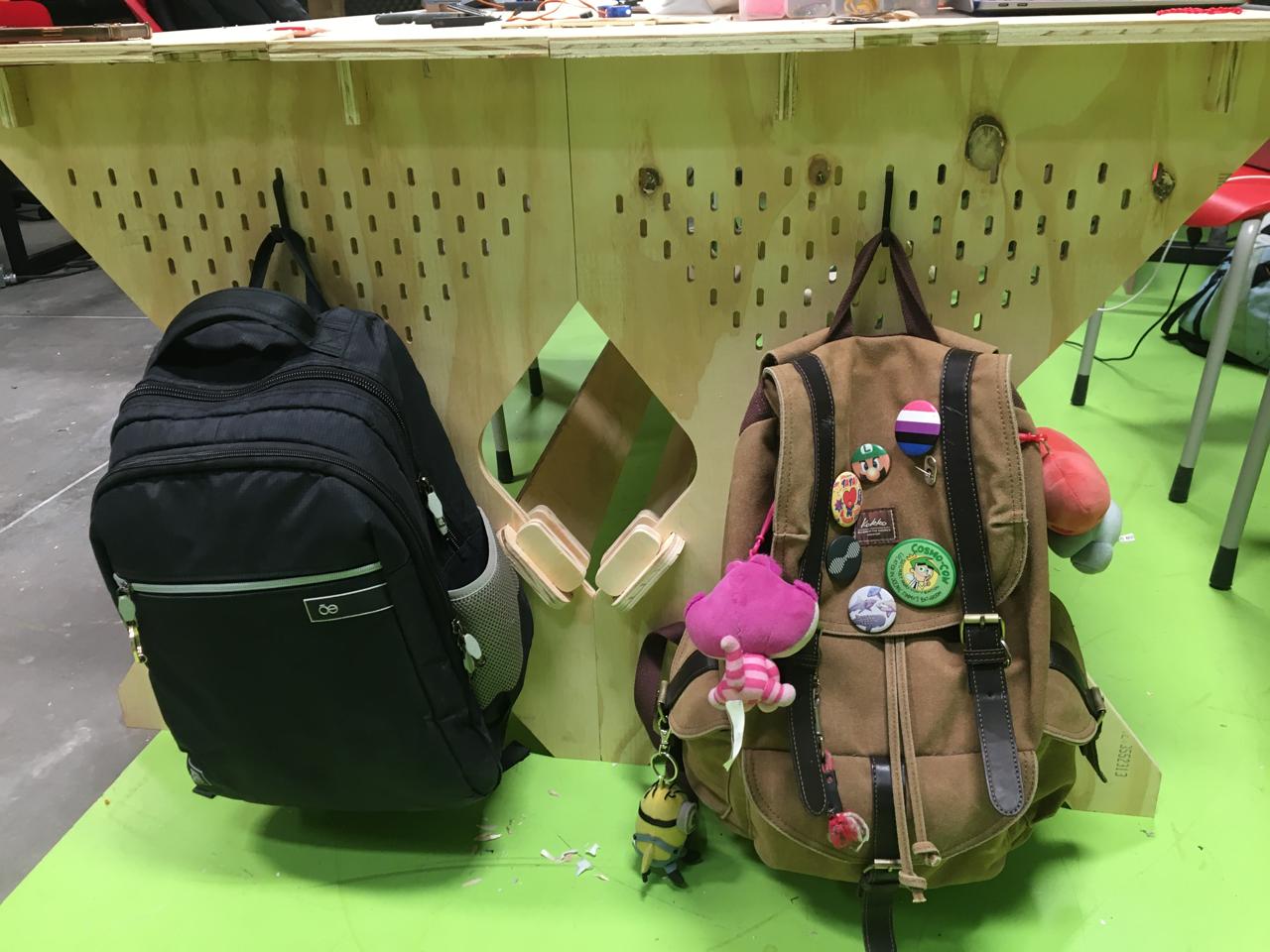
Because I lost a lot of time trying to figure out how to make the speaker work I could only design this hooks for the pegboard, they work for hanging backpacks, purses, headphones, etc. They hold between 10-20 kg.
Final usage and assemby
After everything is done we can play around with the desk here are some examples of how you can arrange your desks, the original idea was to build four but because of time and resources I could only buid two so if you ever try it and make more please share.
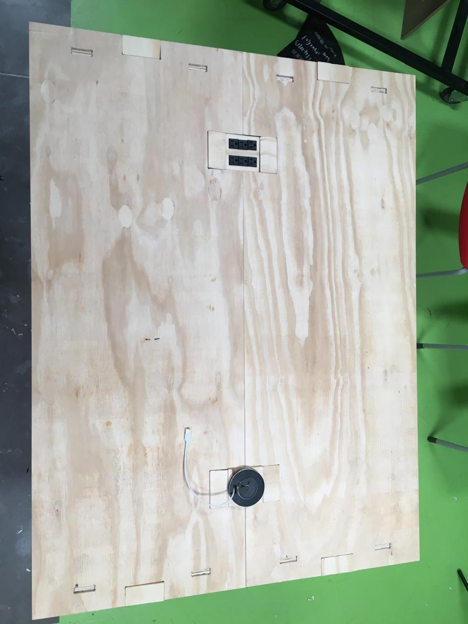
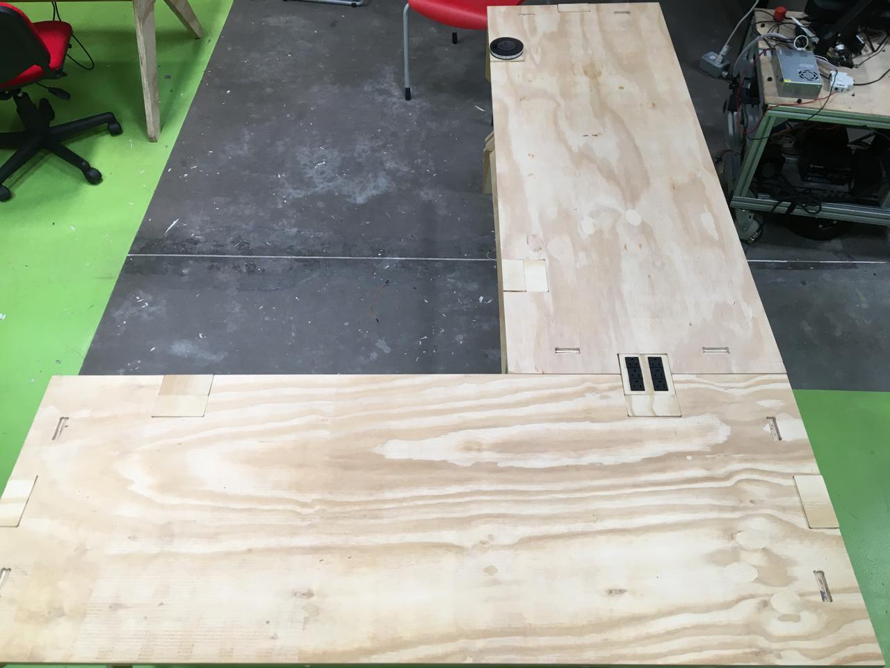
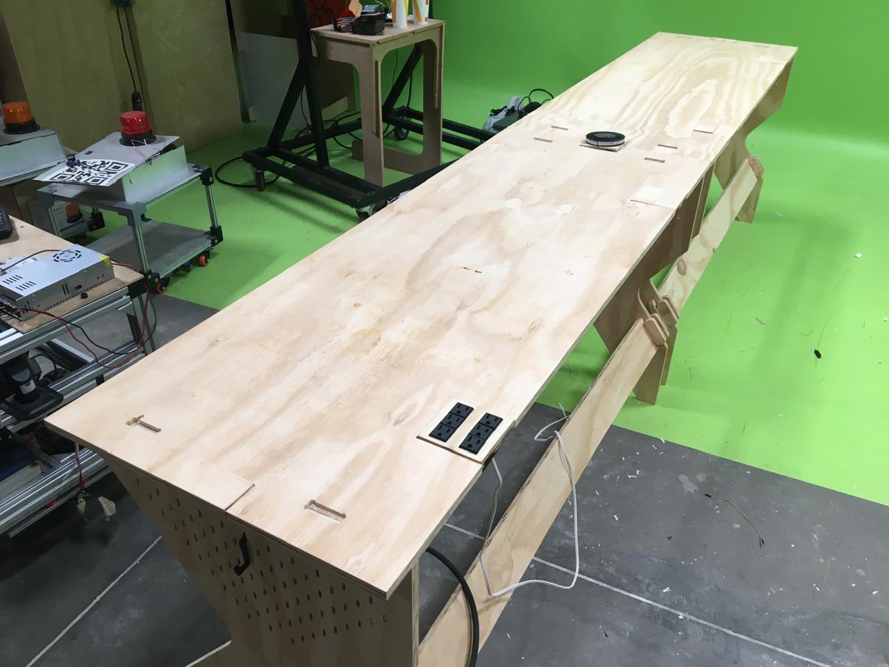
It's really easy to fit the unions, almost like LEGO.
Comments from people that have used the desk
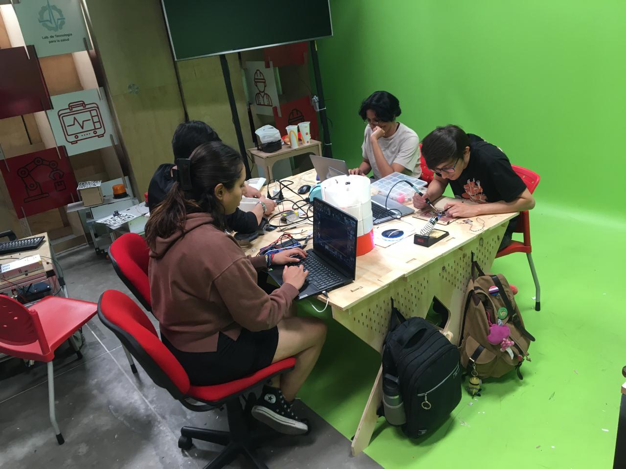
I asked some of the people that worked on the desk to make a comment and something that they would change or add to the desk.
| "I found it to be a great element for coworking. As a designer, we are always working in groups, and having a tool that adapts to our way of working is more than ideal. Perhaps adding some wheels with locks would help make it easier to change the position of the desks." | "The desk was very functional when I used it because it adapted to the workspace we needed. By being able to change the position between the tables, we were able to create a better area for sharing materials, voltage outlets, and other tools. Personally, I would paint it and add more lamps in case additional light is needed at certain points." |
System Integration
Here you can see the systems working together.
Licensing
A Fabulous Desk by Guillermo Michel is licensed under CC BY-NC 4.0
