14. Interface and Application Programming
Qt designer
For this week I used Qt designer, Qt Designer is the Qt tool for designing and building graphical user interfaces (GUIs) with Qt Widgets for user interface. Check Interface and Application Programming Guide Ibero Puebla Fablab for more info.
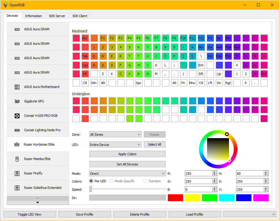
For my final project I wanted to make something like the OpenRGB interface to control an RGB lamp.
So first we need to know how Qt Designer works, first we need to download it, you can click to download it form the page. Also you need to type on your CMD terminal: pip install pyqt6.
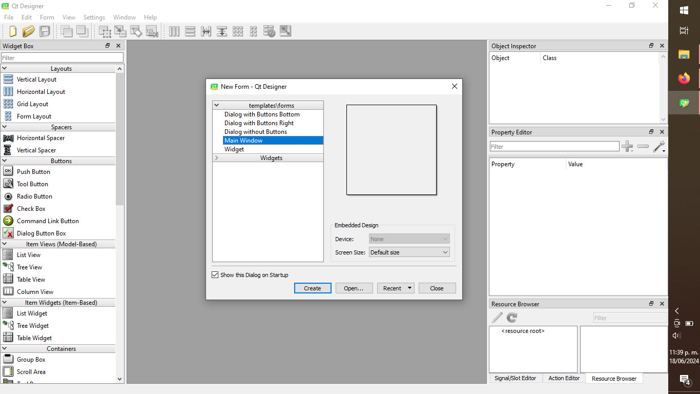
When we first open Qt Designer this is what we see, the whit box in the middle is our canvas
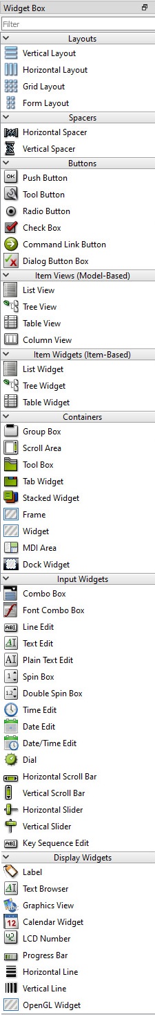
On the left side you can find all the different widgets you can add to your design, in y case I will be using spacers, buttons and dials, among others. You just need to drag them to your canvas and place them wherever you want.
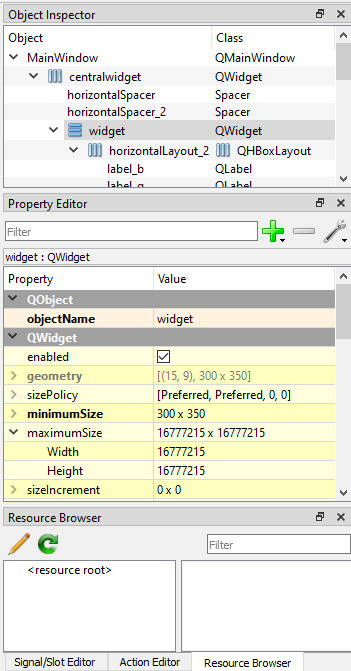
On the right side we have the object inspector and property editor. In the object inspector we can make assignments on the objects and on the property editor we can manually change the layout, size, font, among others.
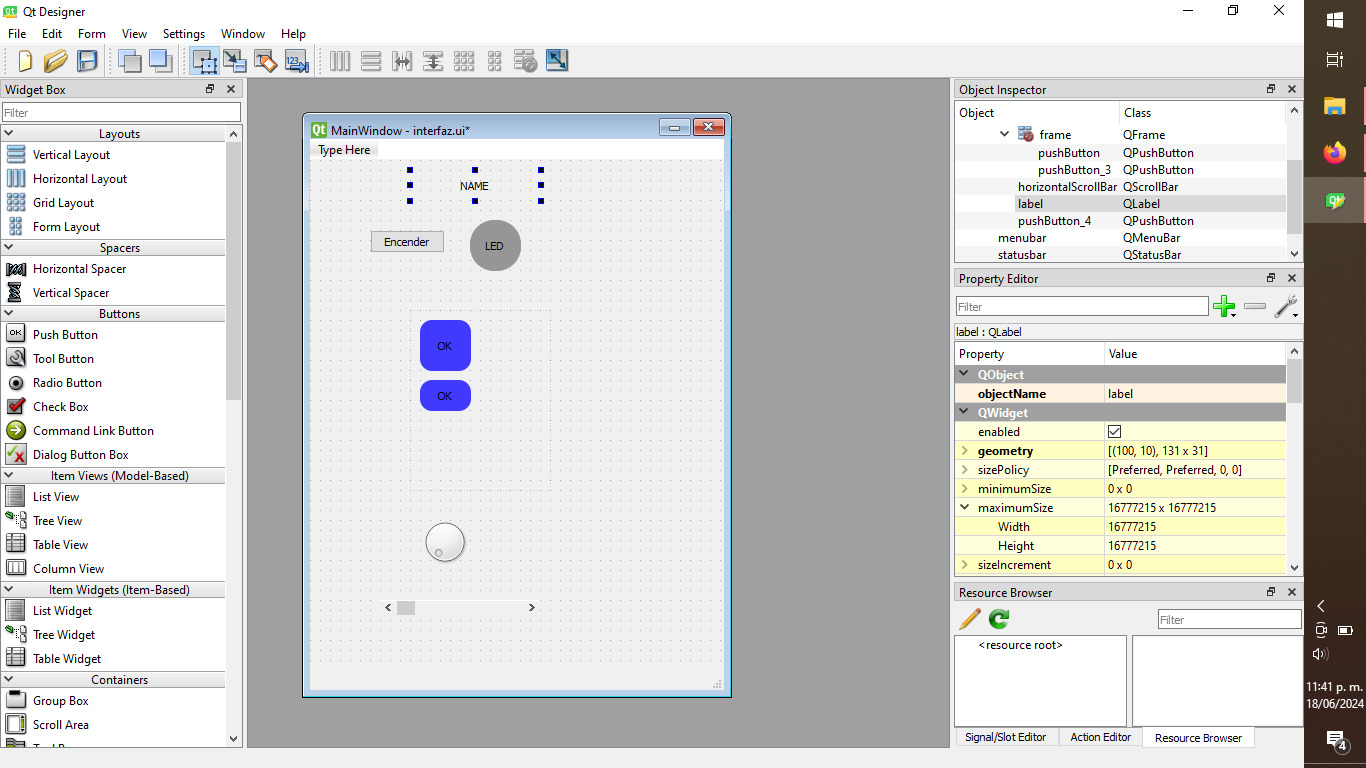
First I added some buttons and a dial, to test some other features.
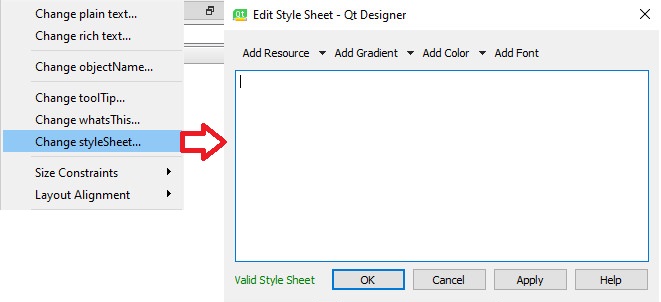
You can right click on any object and select Change styleSheet in order to change shapes of the objects, for example you can give a fillet of any number of pixels to make the buttons less square. In order to type the styleSheet you need to know the syntax, I used this website as a guide.
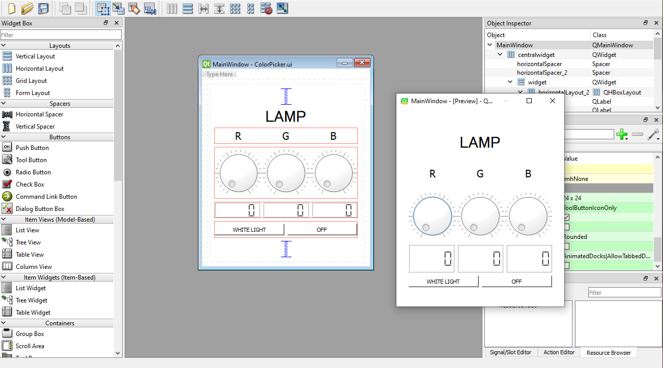
In the end this is what my interface looks like, it has some spacers, two buttons to turn off the LED strip and to turn it white, it has three LCD that range from 0 to 255, three dials, etc.
Python logic file
When we make an interface on Qt it generates two Python files, the most important one is the logic file, in this files we can make the communication with our microcontroller and other changes, for example I added this line:
self.setStyleSheet(f"background-color: rgb({red}, {green}, {blue});")
What this does is that it changes the background color accordingly to the combination on RGB selected.
As you can see it's a very long code but this code helps us communicate pur interface tou our board, it works as a transmitter, you can click here but I would advice you download all the files from the bottom of the page

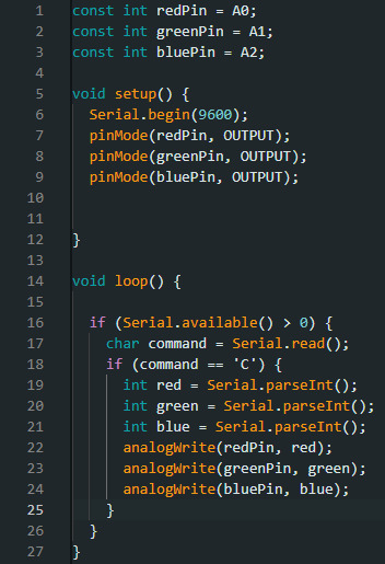
Microcontroller code
Next, we also need a file for out microcontroller, in this case I usea a XIAO, so I coded in c++, this file recives the variables from the interface and uses the pins as outputs to control the colors on the led strip. You can click here to download this code.
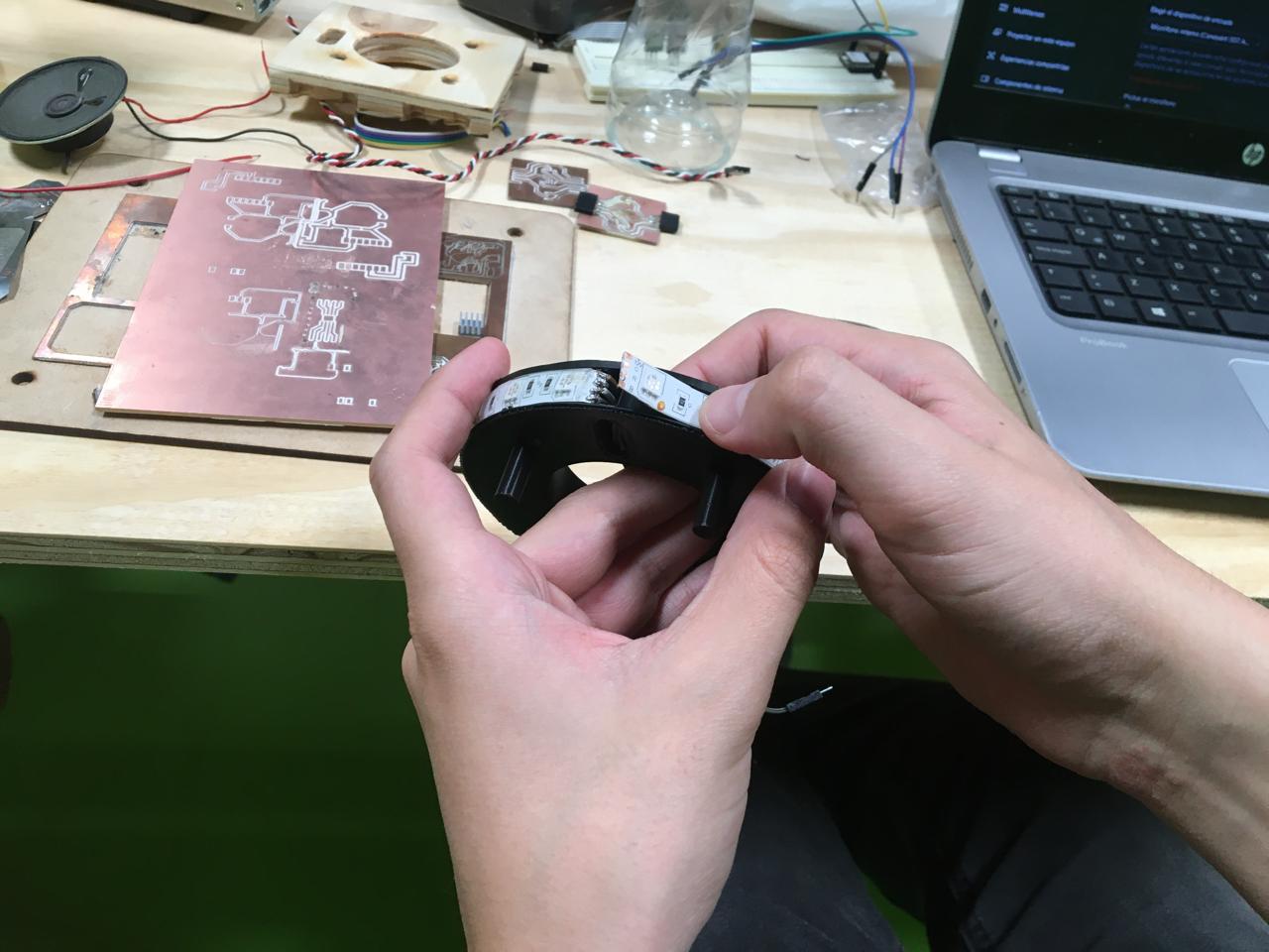
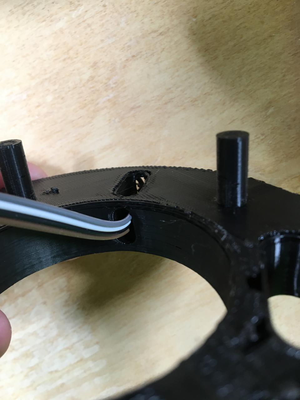
Connections and placement
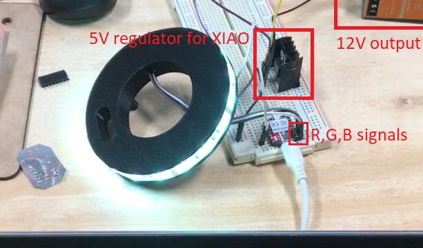
I used a 3d printed base for the LED strip.
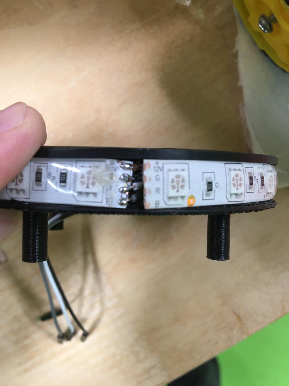
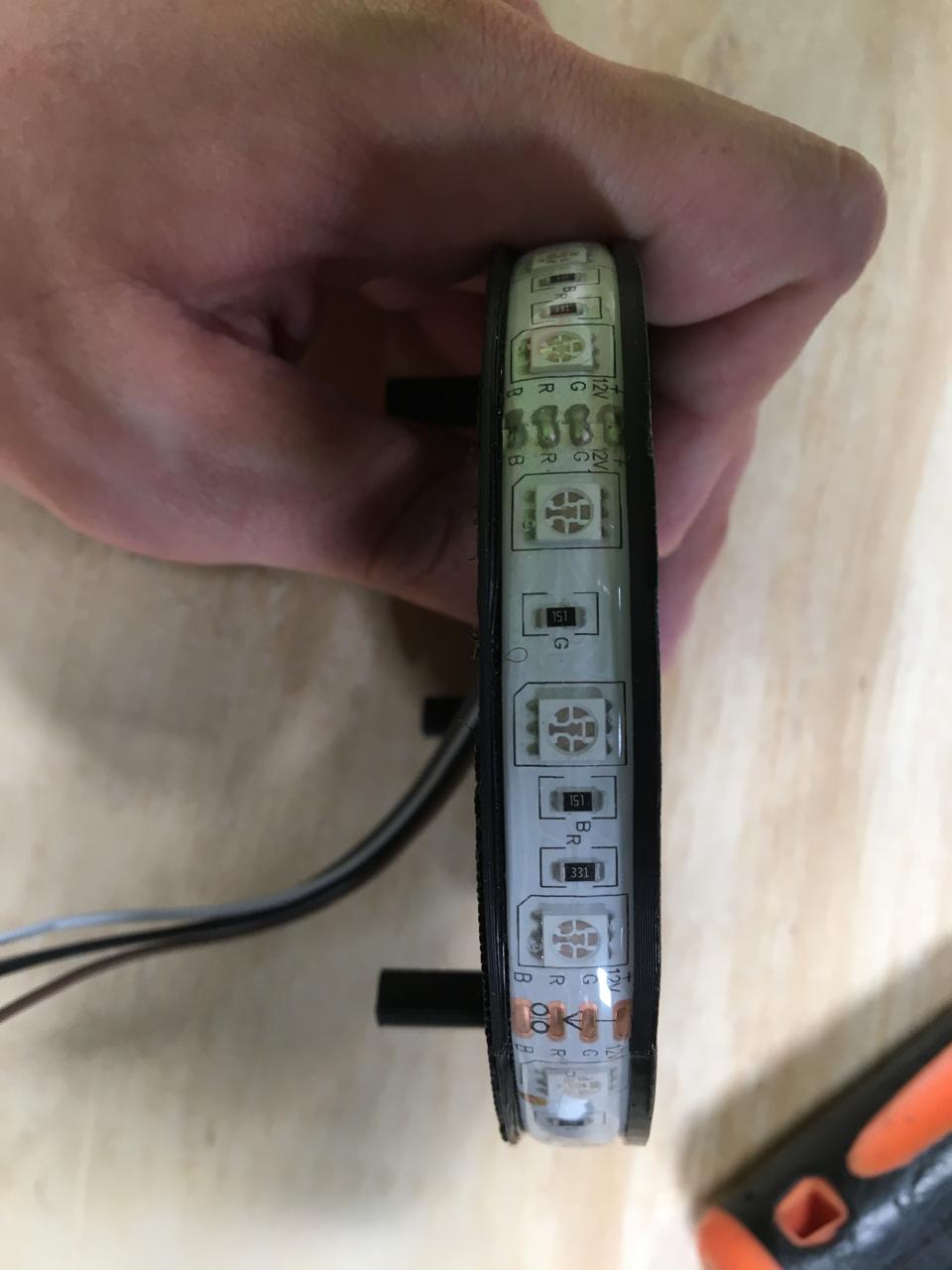
I assigned 3 different pins for R, G and B,used serial to achieve communication with the interface and analog write to send the outputs to the LED strip.
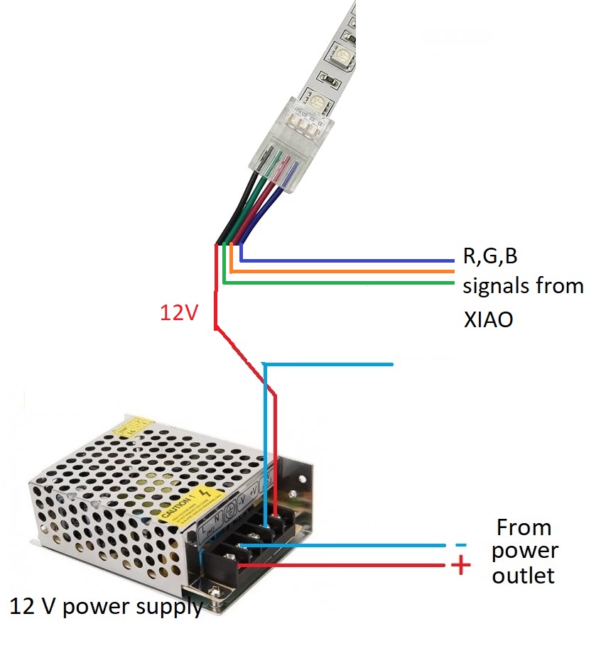
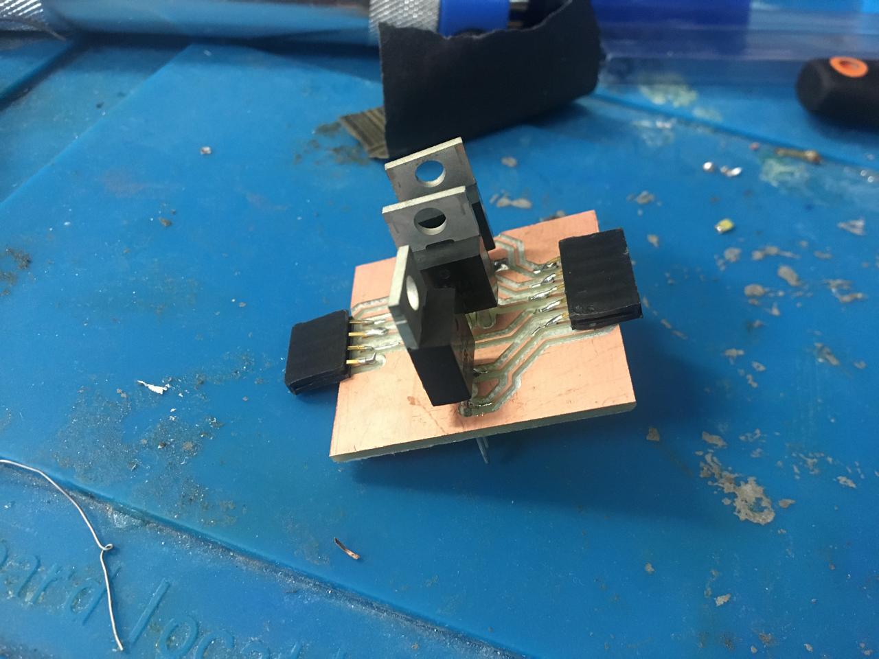
This is how I connected everything to get the 12V for the LED strip on the testing stage and I noticed the LEDs were not as bright as they should be, so I investigated and turns out the signals get a bit of noise so I needed to correct them, for this I used MOSFETs.
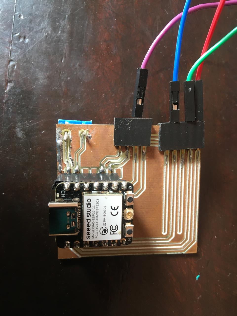
Afterwards I moved everything to a board I developped to host the XIAO and connected another one to host 3 MOSFETs to make the LEDs shine better you can check this out in my final projectpage.
Finally we have a video of the interface working, this was used in my final project.