WEEK 6
EMBEDDED PROGRAMMING
For this week we worked with the board designed during week 4 of electronic production, easy, isn't it ?, at least that's what my instructors say every week, although sometimes it's something too new for me, like programming!
During this week I learned programming basics during the elaboration of the group delivery, you can visit the link to take a look at all the microcontroller models and it's architecture that are in FabLab Puebla, also you can see a comparison of the syntax of C++ and Python with some examples.
Here is a summary of the basics for programming in both C++ and Python, which were the ones I used for this week's assignment.
BASICS!
VARIABLES : It is a place where you can store data, basically it works as a memory.
What kind of data can I store?
- int - integer number
- float - decimal number
- string - character string
- bool - true or false
C++
In C++ you have to say the type of variable to be used.
		int x = 10;
		float y = 20.5;
		std::string name = "Alice";
		bool is_valid = true;
Python
In Python the variable type is set to automatic according to what you have assigned to it, but it can still be edited.
		x = 10          # int
		y = 20.5        # float
		name = "Alice"  # str
		is_valid = True # bool
CONTROL STRUCTURE : It is about decision making and conditionals, such as if this happens, then that will happen. The most basic structure is the if - else.
One way to chain conditionals is to use else if which practically means "If this does not happen, then this will happen"
C++
In C ++ first goes "if" and then the condition that I want to happen between brackets ( ) and between brackets { } we put what will happen if that happens
	if (x > 10) {
		std::cout << "Greater" << std::endl;
	} else if (x == 10) {
		std::cout << "Equal" << std::endl;
	} else {
		std::cout << "Lesser" << std::endl;
	}
Python
Python uses tabs instead of square brackets to indicate what it belongs to.
		if x > 10:
			print("Greater")
		elif x == 10:
			print("Equal")
		else:
			print("Lesser")
BUCLE : It is something that repeats indefinitely. There are 2 types: For: It is defined by start, end and change parameters & While: It is infinite, because it does not have a number of times to execute, so it can be infinite. It has a condition as if it were "if".
C++
for (int i = 0; i < 5; i++) { // For loop
    std::cout << i << std::endl;
}

int i = 0;
while (i < 5) {               // While loop
    std::cout << i << std::endl;
    i++;
}
Python
	for i in range(5):  # For loop
		print(i)

	i = 0
	while i < 5:        # While loop
		print(i)
		i += 1
FUNCTION : A task is packaged so as not to have an infinite number of lines of code that are repeated over and over again. So it is packaged in a single "subprogram" in order to simplify steps and the code is not difficult to read or interpret. First the function is defined and then it is called and given values, or these values are changed.
C++
C++ gives a type of variable and according to the type of variable is the data that is going to return.
	// Defining a function
	int addNumbers(int a, int b) {
		return a + b;
	}

	// Calling a function
	int result = addNumbers(5, 3);
Python
Python uses def to define the function, in brackets are the values I need and with tabulation is what it is going to do.
		# Defining a function
		def add_numbers(a, b):
			return a + b

		# Calling a function
		result = add_numbers(5, 3)
Will C++ or Python be better?
The resolution of this question could really summarize the language to use for this week's practice, however, I was already decided to use both languages from the beginning, and while Python has the advantage of being easier to interpret, it has the disadvantage of being interpreted code, it runs inside the computer and sends one command line at a time so it is slower; and on the other hand C++ being compiled code and run natively inside the computer, it can be faster.
IS IT NECESSARY TO PREPARE SOMETHING BEFORE PROGRAMMING?
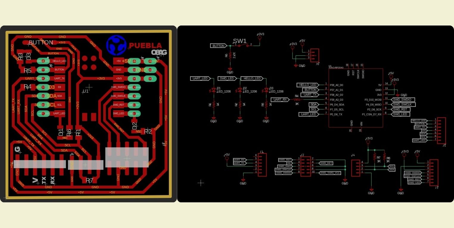
- Well, to start, you need the board and to know it, in this case I am going to use the one I made for the week 4 delivery , so I will use the microcontroller "Seeed XIAO RP40" from Seeed Studio.
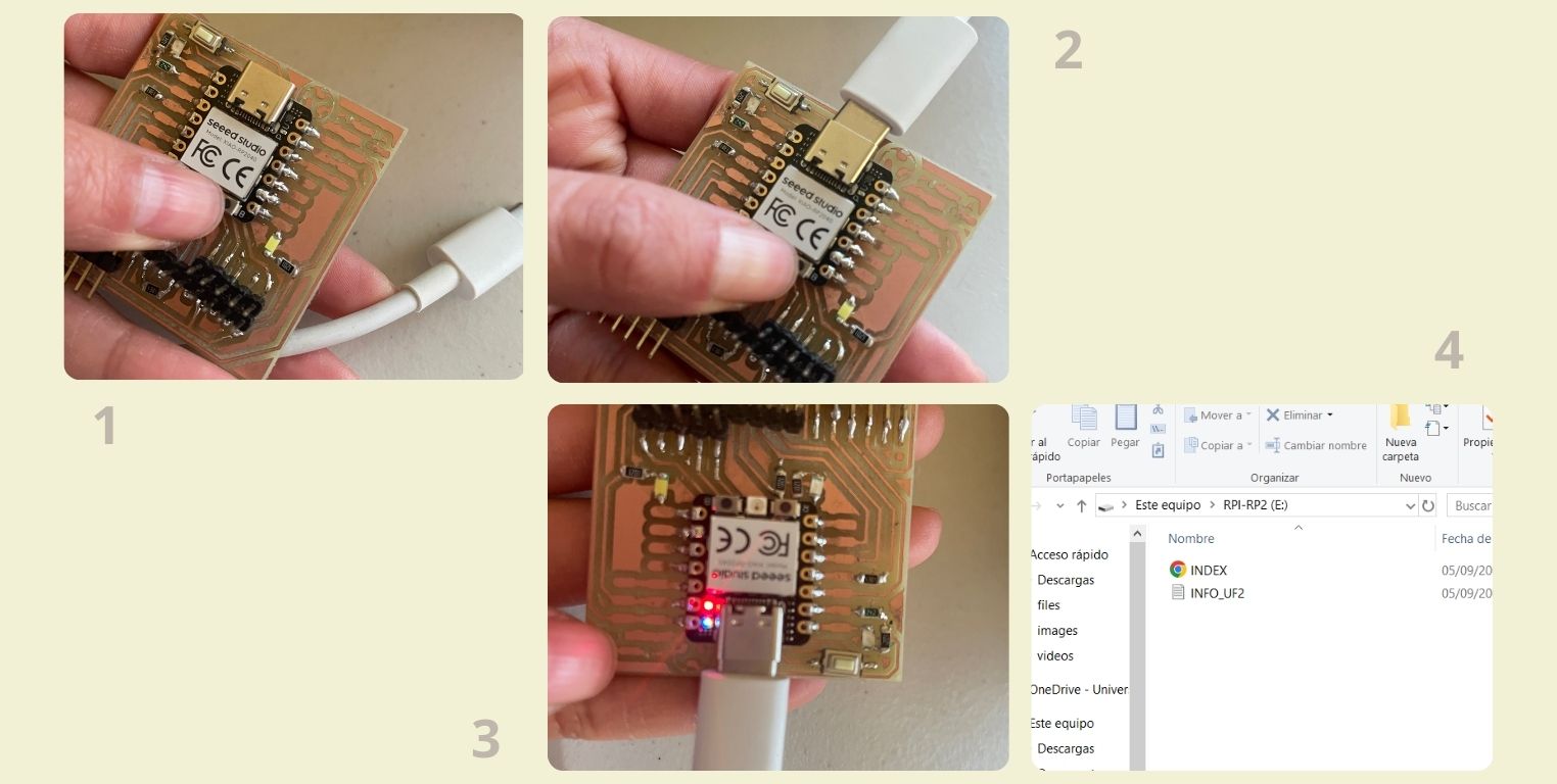
- You have to enter the Blootloader Mode to load a new operating system, to do this follow the next steps:
- Press and hold the B button.
- Connect the Seeep Studio XIAO PR2040 to the computer with a type C cable.
- You can release the B button.
- On the computer it should appear as a USB. It shows the blank and empty operating system.
General Features Seeed XIAO RP40:
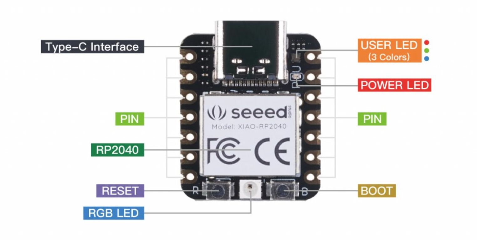
This microcontroller is compatible with Arduino, CircuitPython and MicroPython; although you can also use the Thonny editor to program, as if you were using Raspberry Pi Pico. Depending on the program you are going to program with, and therefore the language you use, you have to load the compatible operating system. On top of the board it has an RP2040 chip integrated into the PCB, which runs something called UF2, an internal executable that functions as the operating system. Like other boards, it has two buttons, one as a reset and one as a boot button. It also has a red power LED and an integrated RGB LED. A Neopixel LED is also available on the board that can be programmed. The board has a USB Type-C interface for programming and Serial Communication.
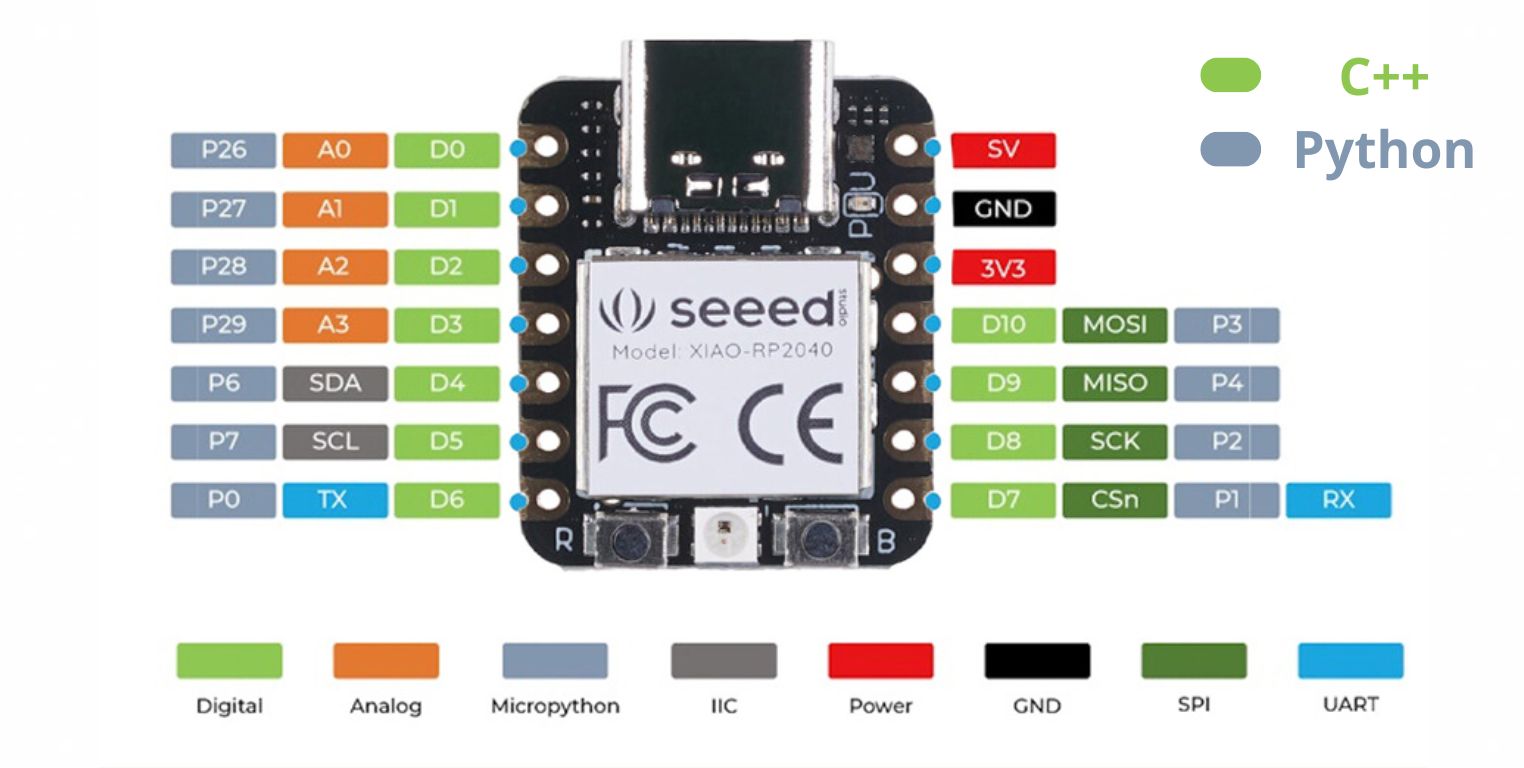
Seeed XIAO RP40 pin configuration:
There are 14 GPIO PINs with input, output and interrupt functions on Seeed Studio XIAO RP2040, in which there are 11 digital pins, 4 analog pins, 11 PWM pins, 1 I2C interface, 1 UART interface, 1 SPI interface and 1 SWD Bonding pad interface.
If it does not detect it, it could be because the cable being used is a ground voltage cable and not a data cable. The first time it happened to me when I tried to use the cable I charge my headphones with, but any cell phone or iPad cable works fine.
LET'S START PROGRAMMING!
C++
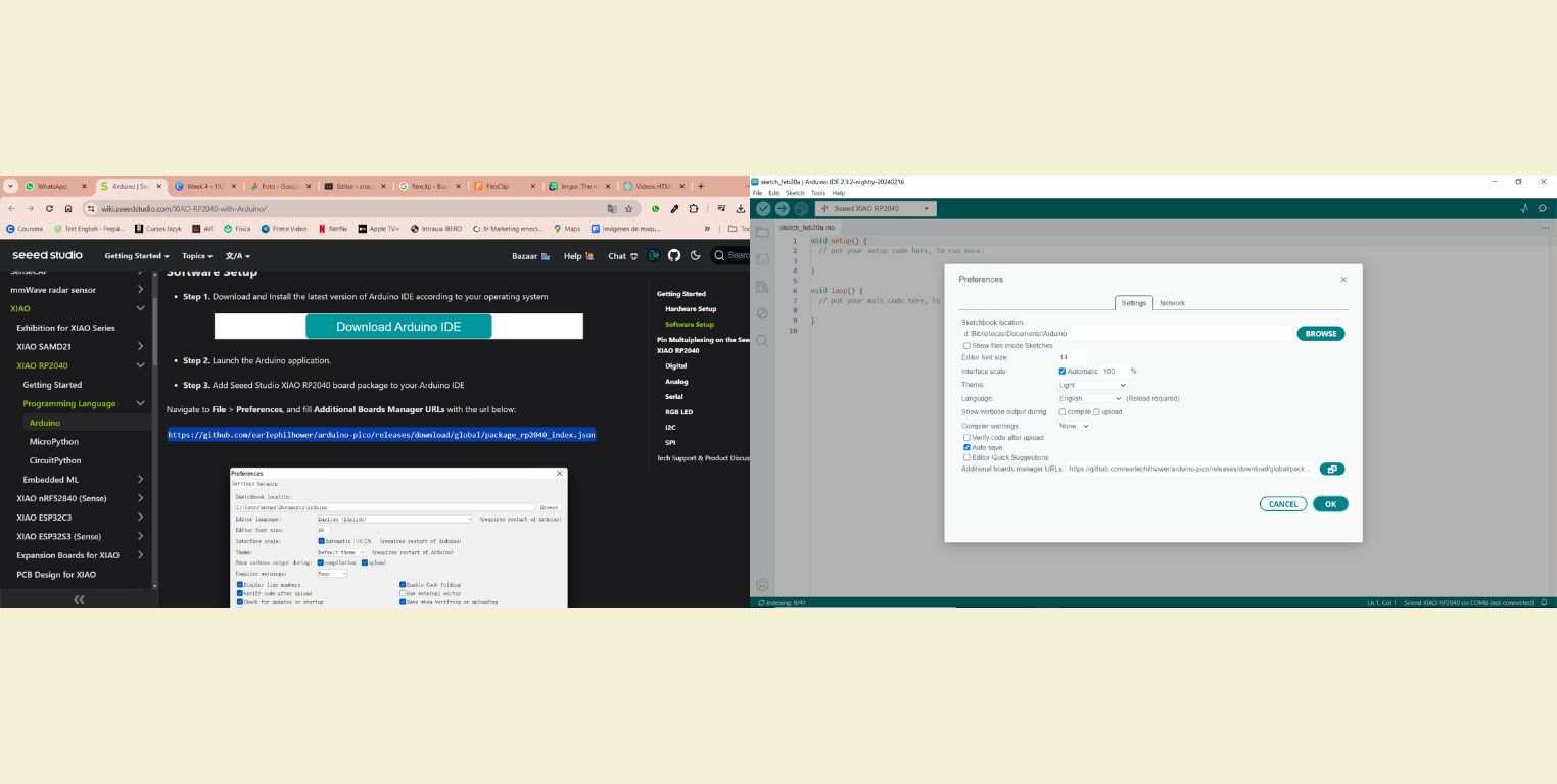
To program in C++ I used Arduino , it's the one I've heard the most about and that's why I've seen the most tutorials, so being new to this I need as much information as possible. You can download the program for free at the following link
For the Arduino to read the board you have to download the library you need. For this on the internet I searched the name of the XIAO and from a page I got the link corresponding to Arduino. In the same page is the step by step of how to do it.
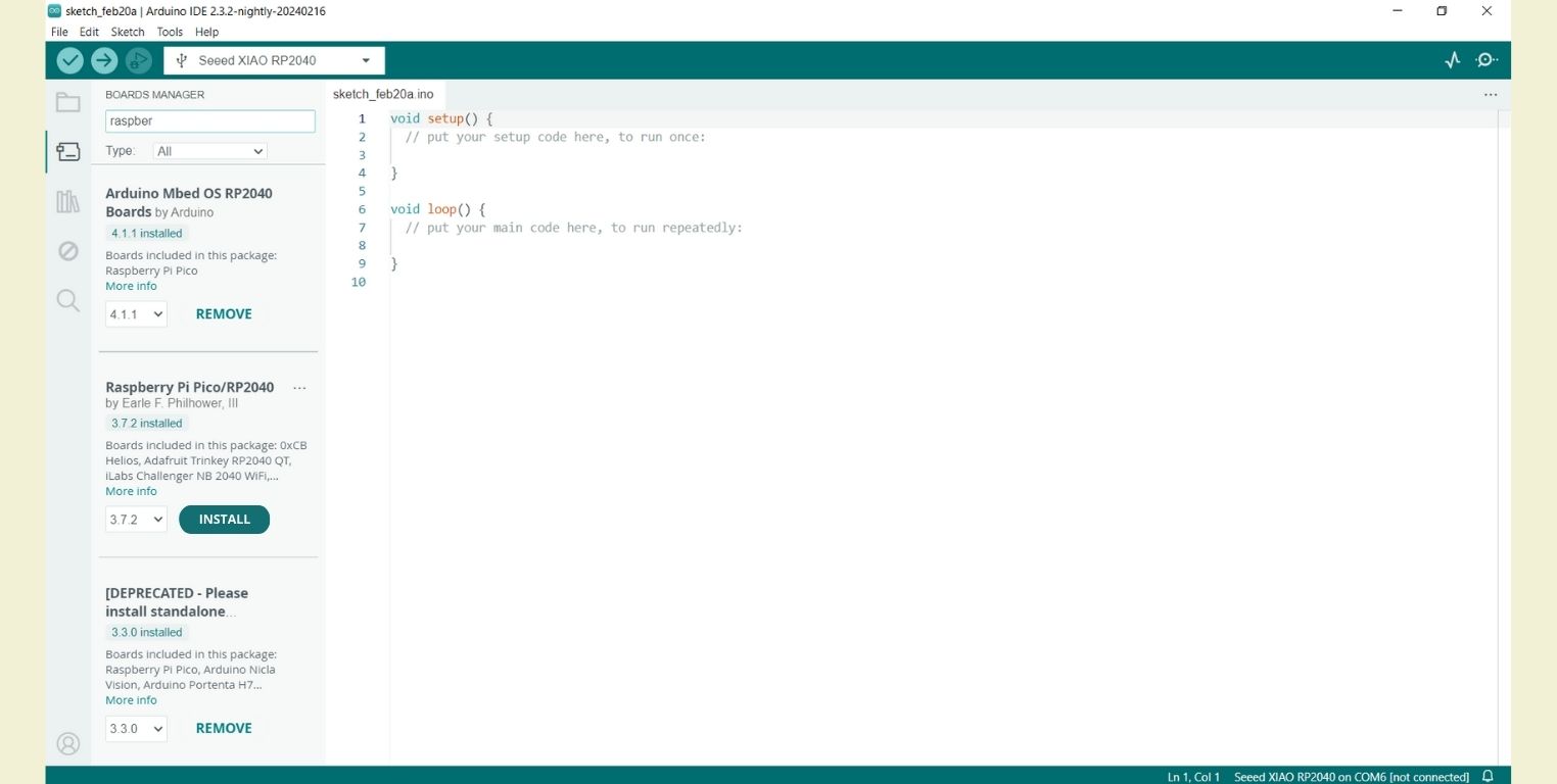
Then I downloaded the Board Manager corresponding to the XIAO. For these I searched for Raspberry Pi Pico/RP2024 and installed version 3.7.2.
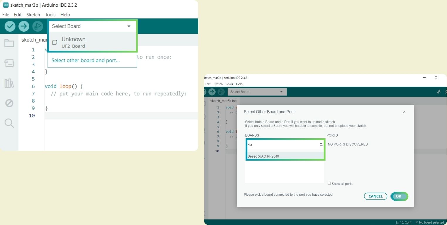
Then all you have to do is select the board to work, if for some reason it doesn't seem to detect it, try re-entering "Blootloader Mode".
Code to flash a led
What this code does is to turn on a LED and give it a delay time so that it turns off before turning on again and this blinking can be seen. If this time were not given, it would be done so fast that it would not be appreciated, because it works at 40 mega hrz per millisecond, that is 40 million instructions per second, which means that it turns on and off at a 40 millionth of a second, so we will not see it, at most we will only see that it lowers the brightness.
- The first thing to do is to specify the commands (between {} ) to be executed with the void setup () function.
- Then you name the commands. In this case I did it with the instruction pinMode () followed by the number and type of pin to which it is connected. To define the pin I made use of the support images showing the XIAO skeleton and the board. Once this was done I declared the led as an output pin.
- After this came the function void loop (), the place where the magic happens, or well the programming, but we can call it magic when it works. All commands are written in square brackets, and with this specific function, the microcontroller starts by reading the first command to the end and returns to the first one to repeat the sequence countless times.
- Then comes the function digitalWrite(), this requires that the pin has been declared before as an output pin so that it can be given a logical HIGH condition and this function I wrote it again below but now with the LOW condition.
- Before finishing I added the delay() function, where you specify the time it will wait before turning the led back on. The value of 1000 represents one second, and you can really modify it so that the blinking becomes slower or faster, always taking care that this value is not set to 0 because of the above mentioned.
			// the stup function runs once when you press reset or power the board
			void setup() {
			// initialize digital pin LED_BUILTIN as an output
			pinMode (D7, OUTPUT);
			}

			// the loop function runs over and over again forever
			void loop() {

			digitalWrite(D7,HIGH);  //turn the LED on (HIGH is the voltage level)
			delay(1000);           // wait for a second
			digitalWrite(D7,LOW); // turn the LED off by making the voltage LOW
			delay(1000);         // wait for a second
			}
In the images below you can see that I did this test by changing LEDs, to check that all of them worked correctly, and it also helped me to find out to which pin each LED was connected.

Code to turn on a LED by pressing a button
This code allows that by means of a button a led can be turned on. This Led can be any of the 3 that are soldered on the board, but for this test I did it with the one located on pin D0.
- The first thing was to declare a variable type with int to store the button as state, so that this variable is equal to what the button can read. So change what the direct button reads to state.
- Then, inside void setup() put the commands to declare the led as an output pin and the button as an input pin.
- Then, within the void loop () the system state was declared as the button reading (because from this the program will be executed) with the instruction digitalRead followed by the pin where the button is connected.
- The next thing was to set the start of a condition with If so that when the button is HIGH, then the system sends an instruction with digitalWrite for the button that is connected to pin D0 and it turns on. With else an instruction is given to the system in case the condition is not carried out, this says that therefore the led connected to pin D0 is turned off.
			// the stup function runs once when you press reset or power the board
			void setup() {
			// initialize digital pin LED_BUILTIN as an output
			pinMode (D7, OUTPUT);
			}

			// the loop function runs over and over again forever
			void loop() {

			digitalWrite(D7,HIGH);  //turn the LED on (HIGH is the voltage level)
			delay(1000);           // wait for a second
			digitalWrite(D7,LOW); // turn the LED off by making the voltage LOW
			delay(1000);         // wait for a second
			}
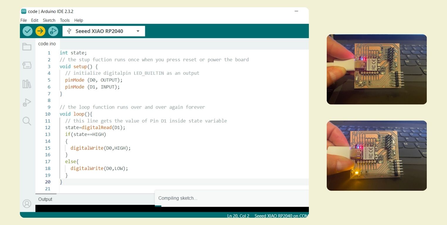
Code to turn on all the LEDs by pressing a button
From the previous code I wanted to turn on not only one led, but all of them at the same time. First it went wrong because I wanted to declare all the leds as output pins in a single pinMode, and the same in the instructions... rookie mistake maybe, I thought I could reduce the code in that way. In the end I ended up declaring them separately, as well as giving the instructions separately as well, and it worked out fine!
			int state;
			// the stup fuction runs once when you press reset or power the board
			void setup() {
			// initialize digitalpin LED_BUILTIN as an output
			pinMode (D0,OUTPUT);
			pinMode (D7,OUTPUT);
			pinMode (D6,OUTPUT);
			pinMode (D1, INPUT);
			}

			// the loop function runs over and over again forever
			void loop(){
			// this line gets the value of Pin D1 inside state variable
			state=digitalRead(D1);
			if(state==HIGH)
			{
				digitalWrite(D0,HIGH);
				digitalWrite(D7,HIGH);
				digitalWrite(D6,HIGH);
			}
			else{
				digitalWrite(D0,LOW);
				digitalWrite(D7,LOW);
				digitalWrite(D6,LOW);
			}
			}
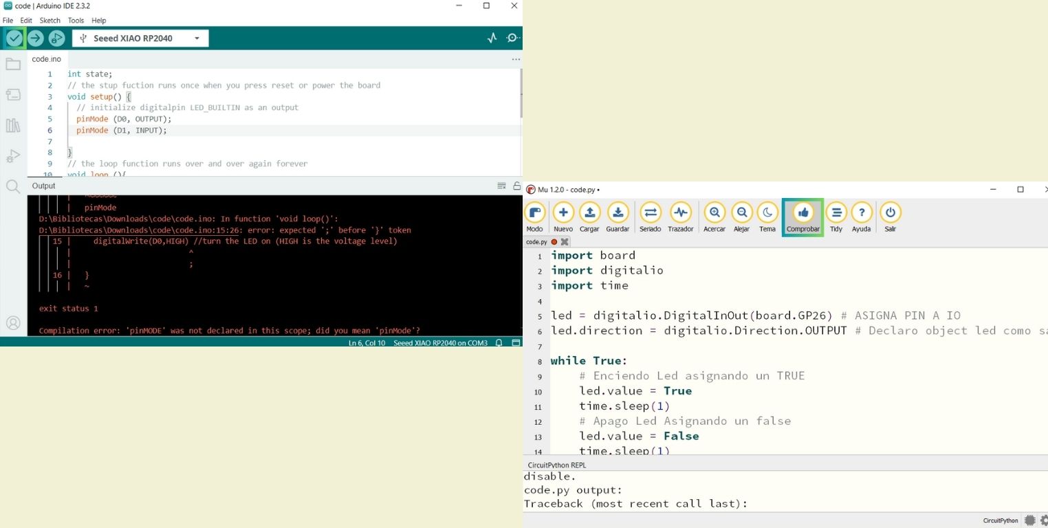
check that you don't have a mistake
I take advantage of the previous experience to talk about something relevant in this programming world. Surely my rookie mistake was just that, a rookie mistake. However, there are very common mistakes like the "=" to assign a value and "==" to make comparatives, probably by writing the code too fast, but here I warn you... Always remember to check the code, both in C++ and Python, below I leave you an image where the tool that helps you to see if everything is ok with the code before continuing is specified. It is also important that you verify that your codes are running within the code file that you find inside the board.
Code to fade the light of a led and increment again
This code consists of turning an LED on slowly and then off slowly indefinitely. I really liked this particular code, because it's a start of what I want to do with my final project. I would like to be able to add different modes in which the lamp can turn on and emit light, and I really liked this fading one.
- To start, I declared the variable int to assign the general values of the led, such as the pin it is connected to, its brightness, and how many marked changes the led would have when fading. And as you can see this time I tried a different way of declaring the led. Actually before I would have thought that it can only be done in one way, but now I see that it can't, as long as it is understandable for the program.
- In the function void setup() I declared the led as an output pin.
- In the function void loop() I inserted the analog functionanalogWrite to control the brightness of the LED. After that I assigned that the brightness will be the sum of the brightness and the fade points.
- Then I set a condition that whenever the brightness was greater than 0 and less than 255, which is the range in which the brightness can be edited, the fade would have a negative value, thus changing the direction of the fade and it can turn on slowly as well as turn off slowly.
- Finally, a delay of just a few milliseconds was set to see the whole cycle of the effect.
				int led = D6;         // the PWM pin the LED is attached to
				int brightness = 0;  // how bright the LED is
				int fadeAmount = 5;  // how many points to fade the LED by

				// the setup routine runs once when you press reset:
				void setup() {
				// declare pin D7 to be an output:
				pinMode(led, OUTPUT);
				}

				// the loop routine runs over and over again forever:
				void loop() {
				// set the brightness of pin D6:
				analogWrite(led, brightness);

				// change the brightness for next time through the loop:
				brightness = brightness + fadeAmount;

				// reverse the direction of the fading at the ends of the fade:
				if (brightness <= 0 || brightness >= 255) {
					fadeAmount = -fadeAmount;
				}
				// wait for 60 milliseconds to see the dimming effect
				delay(60);
				}
Code to change the RGB of the neopixel
In this code you can see how the RGB of the neopixel works, in addition it is included that when pressing a button, the leds turn on one after another, mechanism that I liked a lot, I think that the mechanism merged with the previous one can be interesting in my final project.
- The first thing in this case was to download the library Adafruit_NeoPixel and mention it above with #include, if you do not find it you may be looking for it in the wrong place, as it happened to me.
- Then the function int was used and named power, followed by assigning it the value of 11, and then naming the function int again, but now giving it the value of 12 so that it could be used in the calculation. From what I understood, these values represent in the case of pin the exponent to which the function power will be raised.
- The next thing was to declare with #define the number of pixels, in this case the XIAO RP2040 has only 1. We named led by led underneath. And finally pixels was declared as the one containing number of pixels, pin, etc. As you can see there are different ways to declare what to work with.
- In void setup() was started with pixels.begin, so that when you load the code first the neopixel is turned on. Then the function power was mentioned and given an output instruction. In the case of the button this was INPUT_PULLUP. Followed by all the LEDs with output instructions, the digital write function was added with the input instruction for the power function.
- In void loop() was added a conditional that started with IF, inside this is the digital write function to make a comparison when the button is off. Then performInterestingPattern was added to make an interesting pattern when the button was pressed. Then while was used to say that until the button was released other actions were avoided and a delay of 10 milliseconds was given. Next was an else to say that, if the button was not pressed, to make a pattern of lights with the LEDs. Below you can see in the code the specifications for each pattern, but basically what was done was to turn on a delay time. And in the case of the neopixel, the colors can change depending on the RGB that is put in parentheses, for this test only primary colors were used.
		#include

		int Power = 11;
		int PIN = 12;
		#define NUMPIXELS 1
		#define BUTTON D1
		#define LED1 D0
		#define LED2 D6
		#define LED3 D7

		Adafruit_NeoPixel pixels(NUMPIXELS, PIN, NEO_GRB + NEO_KHZ800);

		void setup() {
		pixels.begin();
		pinMode(Power, OUTPUT);
		pinMode(BUTTON, INPUT_PULLUP);
		pinMode(LED1, OUTPUT);
		pinMode(LED2, OUTPUT);
		pinMode(LED3, OUTPUT);
		digitalWrite(Power, HIGH);
		}

		void loop() {
		if (digitalRead(BUTTON) == LOW) {
			// The button is pressed, it makes an interesting pattern in NeoPixel
			performInterestingPattern();

			// Wait until the button is released to avoid multiple actions by holding it down
			while (digitalRead(BUTTON) == LOW) {
			delay(10);
			}
		} else {
			// If the button is not pressed, it makes a pattern on the LEDs
			performLEDsPattern();
		}
		}

		void performInterestingPattern() {
		// We make the NeoPixel flash in an interesting pattern when pressing the button
		for (int i = 0; i < 3; i++) {
			pixels.clear();
			pixels.setPixelColor(0, pixels.Color(255, 0, 0));  // Red
			pixels.show();
			delay(200);

			pixels.clear();
			pixels.setPixelColor(0, pixels.Color(0, 255, 0));  // Green
			pixels.show();
			delay(200);

			pixels.clear();
			pixels.setPixelColor(0, pixels.Color(0, 0, 255));  // Blue
			pixels.show();
			delay(200);
		}

		// Turn off the NeoPixel after completing the pattern
		pixels.clear();
		pixels.show();
		delay(500);  // Small delay before allowing another pattern
		}

		void performLEDsPattern() {
		// Make an interesting pattern on the LEDs
		digitalWrite(LED1, HIGH);
		delay(200);
		digitalWrite(LED1, LOW);

		digitalWrite(LED2, HIGH);
		delay(200);
		digitalWrite(LED2, LOW);

		digitalWrite(LED3, HIGH);
		delay(200);
		digitalWrite(LED3, LOW);

		delay(500);  // Small delay before repeating the pattern
		}
Python
I tried very little in Python, and for that it was necessary to download before the Mu editor , and within the different modes that there are to program inside Mu I chose Circuit Python. Actually, what changes compared to C++ is only the language and syntax, but it is supposed to be easier to understand.
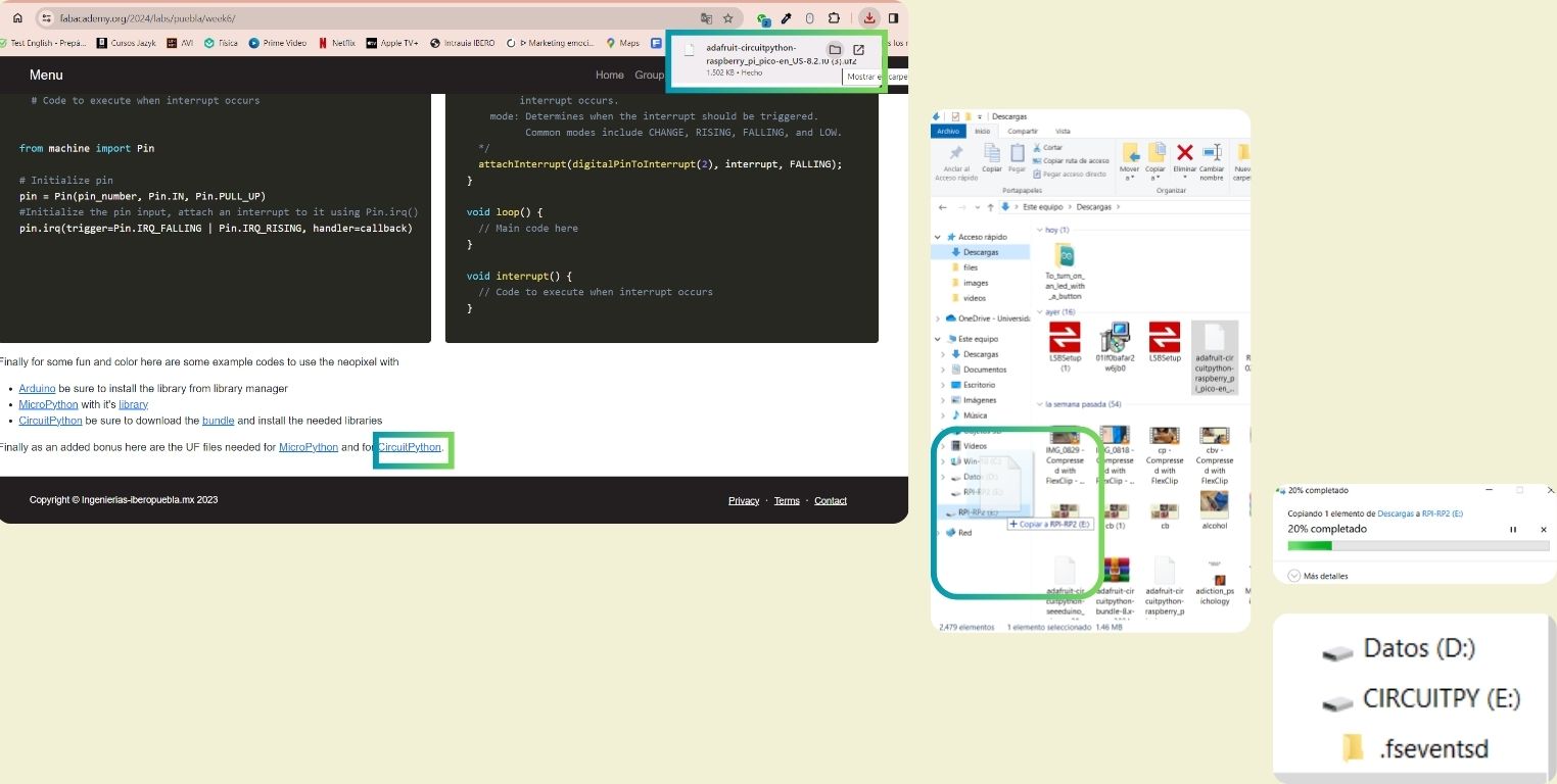
Once the program was downloaded it was necessary to download also the library so I could connect the XIAO RP2040 from my PCB. This you can find inside the group page, then you have to copy the downloadable to the PCB in Blootloader mode. When you do this, it immediately changes its name to CIRCUITPY.
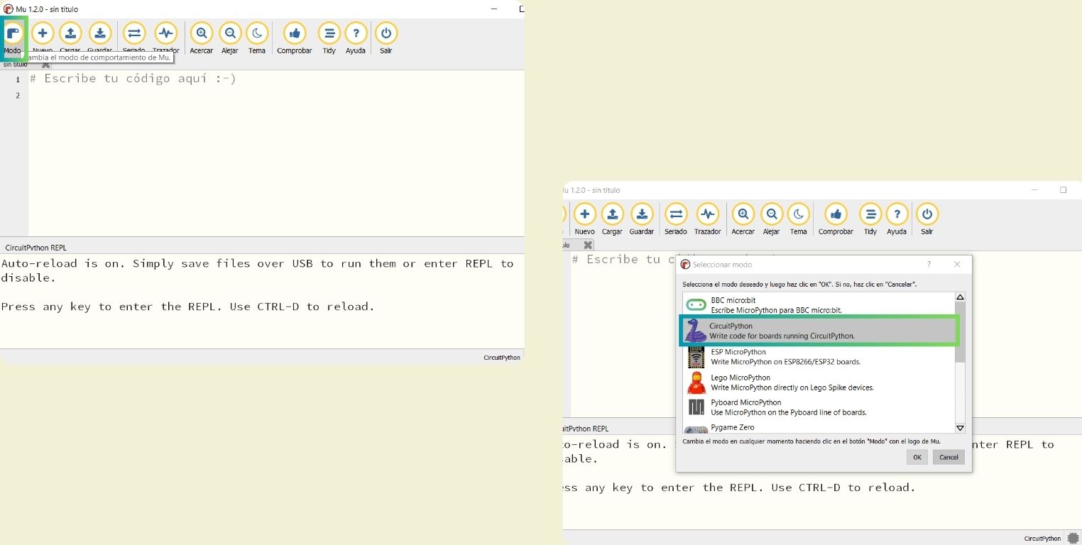
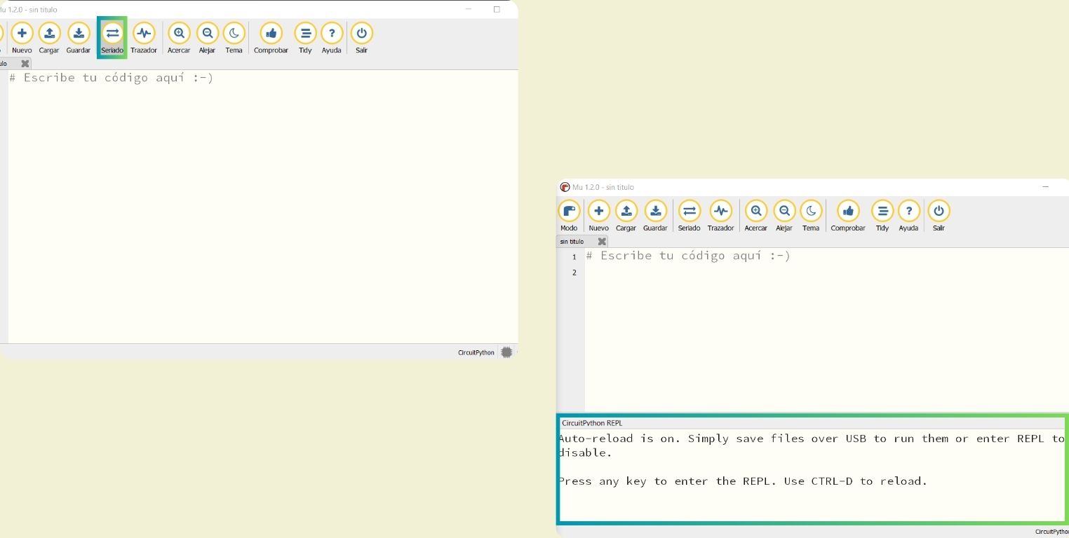
The next step was to open Mu and choose CircuitPython mode which is represented by a purple snake. Then I clicked on serialized so that a terminal appears below, since for the first test I need it to read the data.
Code to read a data and check the connection of the board
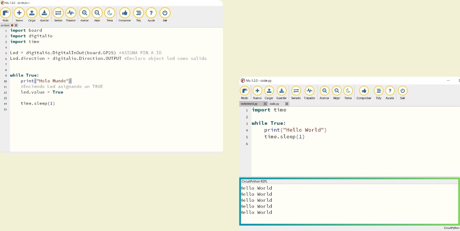
This practice is important because it lets you know that indeed your board is connected in the correct way and is receiving the signals. When you load a code and it doesn't work as expected you can first do a test read to verify that it is connected properly. For example, one of my mistakes during the test was not working in the "code" file, and changing my code file worked.
- This test is about reading and printing data. In this case we print to the screen (and that's what the terminal is for).
- The digitalio library is for the LEDs. For this test we are only using the one connected to the GP26 (in the picture it says "GP25" but it was wrong, I verified it with the reference images at the beginning that show the skeleton of the board and what the XIAO is composed of. The led is also declared as an output object.
- Inside while true it is said that it is going to print "Hello World" every time the value of the led is true, and it is told to do it every second; then instead of delay, in Python sleep is used, and this in turn uses the library time, so the library is always declared at the beginning.
						import time

						while True:
							print("Hello World")
							time.sleep(1)
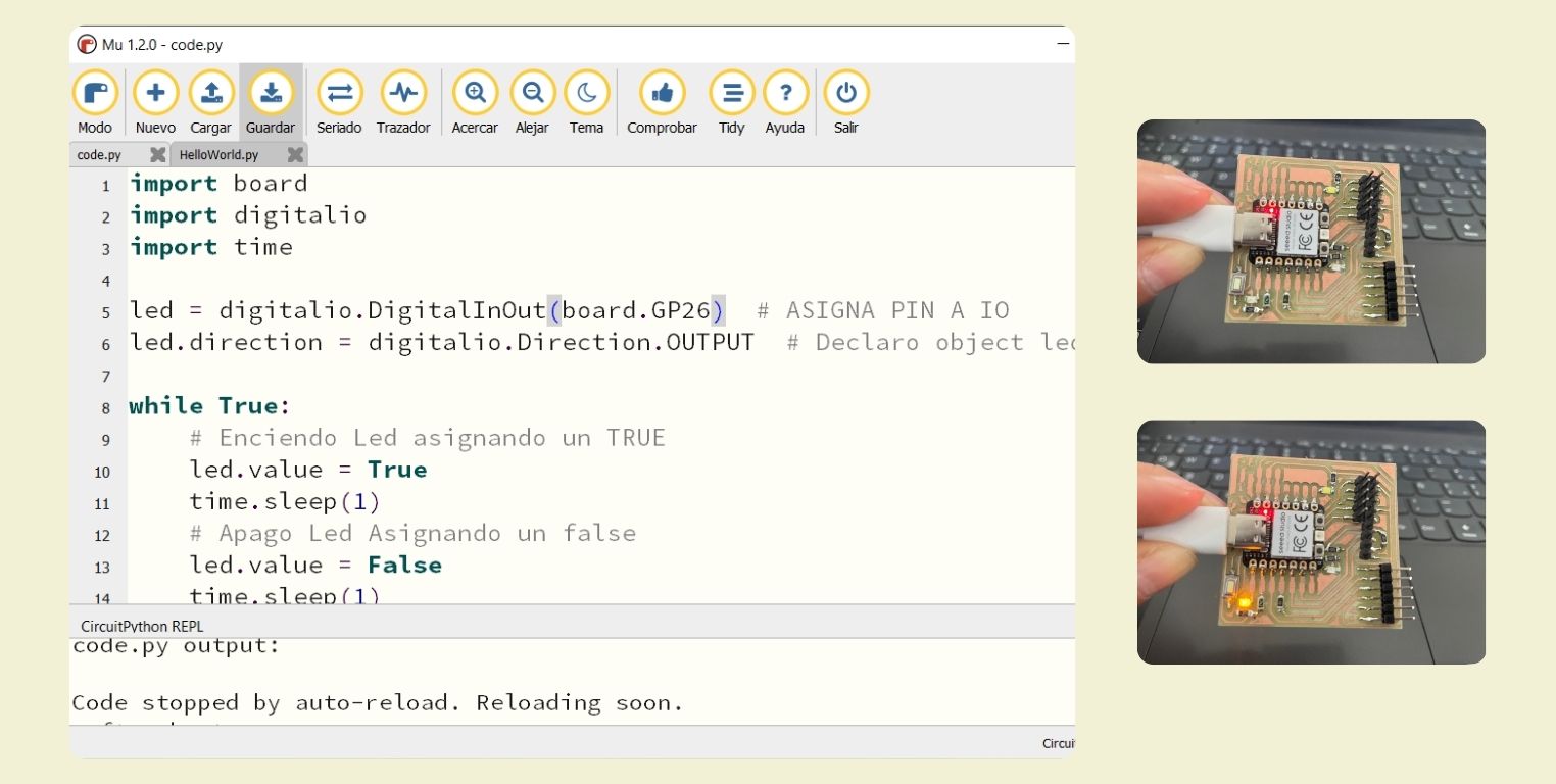
Code to blink a led
Here I basically did the same as in C++ with Arduino, I only changed the syntax for circuitpython, for example, something basic is to use Pull DOWN when by default no signal is detected, and Pixel.show to indicate that a color is displayed, but I will not extend with the explanation of the language. What this code does is to blink a led located in the GP26.
			import board
			import digitalio
			import time

			led = digitalio.DigitalInOut(board.GP26)  #Led position
			led.direction = digitalio.Direction.OUTPUT  # Led is an output object.


			while True:
				# Turn on a Led with TRUE
				led.value = True
				time.sleep(1)
				# Turn off a Led with TRUE
				led.value = False
				time.sleep(1)
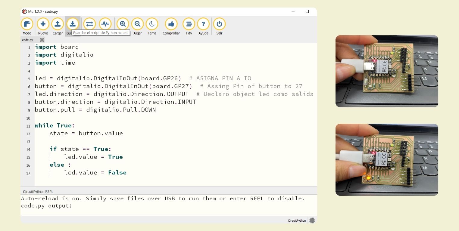
Code to turn on a led with a button
The same thing happens with this code, it was an adaptation of what I did in C++ with Arduino, and allows to turn on a led by pressing a button, the button in this case is connected in GP27.
			import board
			import digitalio
			import time

			led = digitalio.DigitalInOut(board.GP26)  # ASIGNA PIN A IO
			button = digitalio.DigitalInOut(board.GP27)  # Assing Pin of button to 27
			led.direction = digitalio.Direction.OUTPUT  # Declaro object led como salida
			button.direction = digitalio.Direction.INPUT
			button.pull = digitalio.Pull.DOWN

			while True:
				state = button.value

				if state == True:
					led.value = True
				else :
					led.value = False
Change color of the RGB of the Neopixel
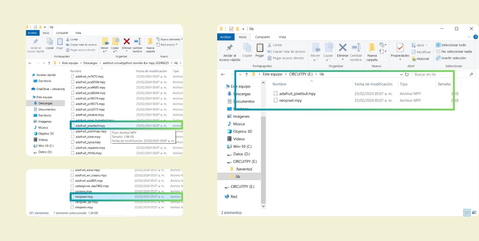
For the following code I had to add the neopixel library in Python. First I did it by downloading from the page the ones I thought they were, but it didn't work for me, so an instructor passed us the necessary libraries. What I did was to copy the "adafrui-circuitpython" file when the PCB was in Blootloader mode.
Then I specifically copied the neopixel file and adafruit_pixelbuf inside the folder called "lib"
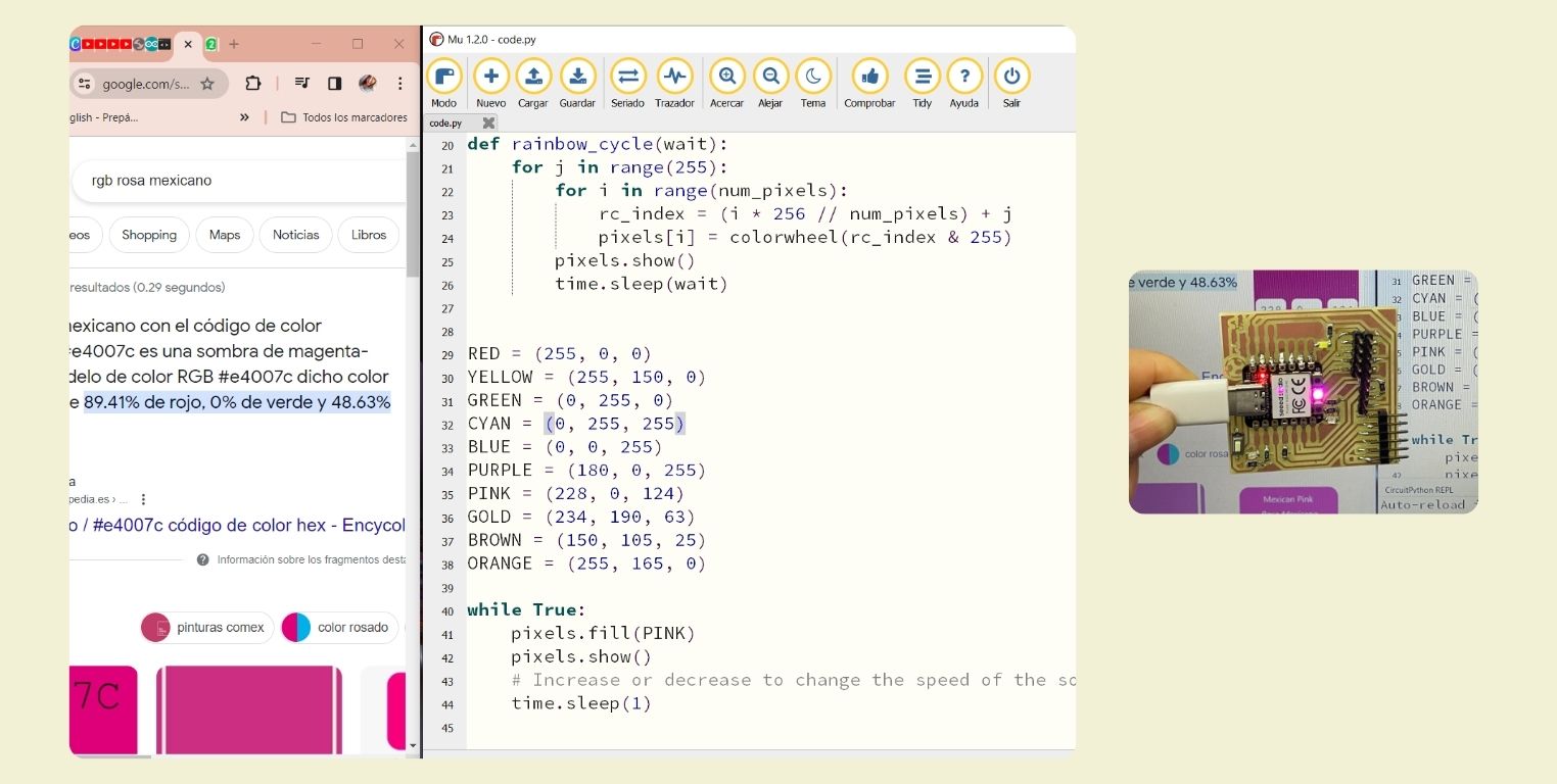
Code for neopixel pink color
For this test I used as a base the code to change the RGB of the neopixel, but I tested it first with a single color, for this I looked for the RGB of the Mexican pink color. In the next code I explain better the code for the neopixel.
		import time
		import board
		from rainbowio import colorwheel
		import neopixel

		pixel_pin = board.NEOPIXEL #The neopixel can be accessed in this way
		num_pixels = 1 #only one pixel

		pixels = neopixel.NeoPixel(pixel_pin, num_pixels, brightness=0.3, auto_write=False)


		def color_chase(color, wait):
			for i in range(num_pixels):
				pixels[i] = color
				time.sleep(wait)
				pixels.show()
			time.sleep(0.5)


		def rainbow_cycle(wait):
			for j in range(255):
				for i in range(num_pixels):
					rc_index = (i * 256 // num_pixels) + j
					pixels[i] = colorwheel(rc_index & 255)
				pixels.show()
				time.sleep(wait)


		RED = (255, 0, 0)
		YELLOW = (255, 150, 0)
		GREEN = (0, 255, 0)
		CYAN = (0, 255, 255)
		BLUE = (0, 0, 255)
		PURPLE = (180, 0, 255)
		PINK = (228, 0, 124)
		GOLD = (234, 190, 63)
		BROWN = (150, 105, 25)
		ORANGE = (255, 165, 0)

		while True:
			pixels.fill(PINK)
			pixels.show()
			# Increase or decrease to change the speed of the solid color change.
			time.sleep(1)
Code to change the RGB of the neopixel
With the experience of the pink color, I looked for other colors. What I did was to test color by color and then make them all change.
- But before that, it is necessary to declare in the code the neopixel, and specify the number in pixel_pin. The neopixels work as if they were chained, each one has a location, if it were in series it would start at 0, 1, 2, 3, 4.
- Then in pixels the brightness level was specified, you must also understand that Pixels.fill is the function for the color.
- Followed by that goes def color_chase, the color_chase function sends the color to all the neopixels in the line. And in the code it is told to wait 0.5 seconds before teaching the next color.
- Then in def rainbow_cycle is given the range in which the colors can be from 0 to 255. Following this comes the list of colors to use with their specific RGB.
- The following is to code the above in while True, in the case of the previous code here was done only one color to show it and give it a waiting time, but for this code more colors were used, then the programming was done for each color.
- Following that in color_chase is the list of colors that would show with 0.1 time between each one.
		import time
		import board
		from rainbowio import colorwheel
		import neopixel

		pixel_pin = board.NEOPIXEL #The neopixel can be accessed in this way
		num_pixels = 1 #only one pixel

		pixels = neopixel.NeoPixel(pixel_pin, num_pixels, brightness=0.3, auto_write=False)


		def color_chase(color, wait):
			for i in range(num_pixels):
				pixels[i] = color
				time.sleep(wait)
				pixels.show()
			time.sleep(0.5)


		def rainbow_cycle(wait):
			for j in range(255):
				for i in range(num_pixels):
					rc_index = (i * 256 // num_pixels) + j
					pixels[i] = colorwheel(rc_index & 255)
				pixels.show()
				time.sleep(wait)


		RED = (255, 0, 0)
		YELLOW = (255, 150, 0)
		GREEN = (0, 255, 0)
		CYAN = (0, 255, 255)
		BLUE = (0, 0, 255)
		PURPLE = (180, 0, 255)
		PINK = (228, 0, 124)
		GOLD = (234, 190, 63)
		BROWN = (150, 105, 25)
		ORANGE = (255, 165, 0)

		while True:
			pixels.fill(RED)
			pixels.show()
			# Increase or decrease to change the speed of the solid color change.
			time.sleep(1)
			pixels.fill(YELLOW)
			pixels.show()
			time.sleep(1)
			pixels.fill(GREEN)
			pixels.show()
			time.sleep(1)
			pixels.fill(CYAN)
			pixels.show()
			time.sleep(1)
			pixels.fill(BLUE)
			pixels.show()
			time.sleep(1)
			pixels.fill(PURPLE)
			pixels.show()
			time.sleep(1)
			pixels.fill(PINK)
			pixels.show()
			time.sleep(1)
			pixels.fill(GOLD)
			pixels.show()
			time.sleep(1)
			pixels.fill(BROWN)
			pixels.show()
			time.sleep(1)
			pixels.fill(ORANGE)
			pixels.show()
			time.sleep(1)

			color_chase(RED, 0.1)  # Increase the number to slow down the color chase
			color_chase(YELLOW, 0.1)
			color_chase(GREEN, 0.1)
			color_chase(CYAN, 0.1)
			color_chase(BLUE, 0.1)
			color_chase(PURPLE, 0.1)
			color_chase(PINK, 0.1)
			color_chase(GOLD, 0.1)
			color_chase(BROWN, 0.1)
			color_chase(ORANGE, 0.1)

			rainbow_cycle(0)  # Increase the number to slow down the rainbow
CONCLUSION
Programming was really a great challenge, especially for someone who had never done it before in such a conscientious way. I loved being able to understand a little more how to do the functions, and I know that it may not be much what I did this week, because I know that my examples are very basic, but I continue learning, and I am very curious to learn how to program with sensors, in fact it was something I wanted to do this week, but given how complex some (not to say many) things were on the way, I think I will leave it for a specific week of sensors, meanwhile I will continue practicing.
PD: I already know how my mouse works when it changes color gradually!
PD 2: During this week I also had a problem with my page, and I see value in documenting it, in case it happens to be needed in the future. I will update it in 1's assigment, since it has to do with GitLab, but I invite you to visit how I explain that you can go back to a previous version of your repository without failing in the attempt.
Files
C++
- Code to flash a led . . . . . . . . . . . . . . . . . . . . . . . . . . . . . . . . . . . download here
- Code to turn on a led by pressing a button. . . . . . . . . . . . . . . download here
- Code to turn on all leds by pressing a button. . . . . . . . . . . . . download here
- Code to fade the light of a led and increment again. . . . . . . download here
- Code to change the RGB of the neopixel. . . . . . . . . . . . . . . . . download here
Python
- Code to read a data and check the connection of the board. . download here
- Code to blink a led. . . . . . . . . . . . . . . . . . . . . . . . . . . . . . . . . . . . download here
- Code to turn on a led with a button. . . . . . . . . . . . . . . . . . . . . . download here
- Code for neopixel pink color. . . . . . . . . . . . . . . . . . . . . . . . . . . . download here
- Code to change the RGB of neopixel. . . . . . . . . . . . . . . . . . . . . download here