WEEK 4
ELECTRONICS PRODUCTION
For this week what we did was the development of a printed circuit board, better known by its acronym PCB. On this board electronic connections can be made quickly to obtain a circuit with mechanical and functional structure.
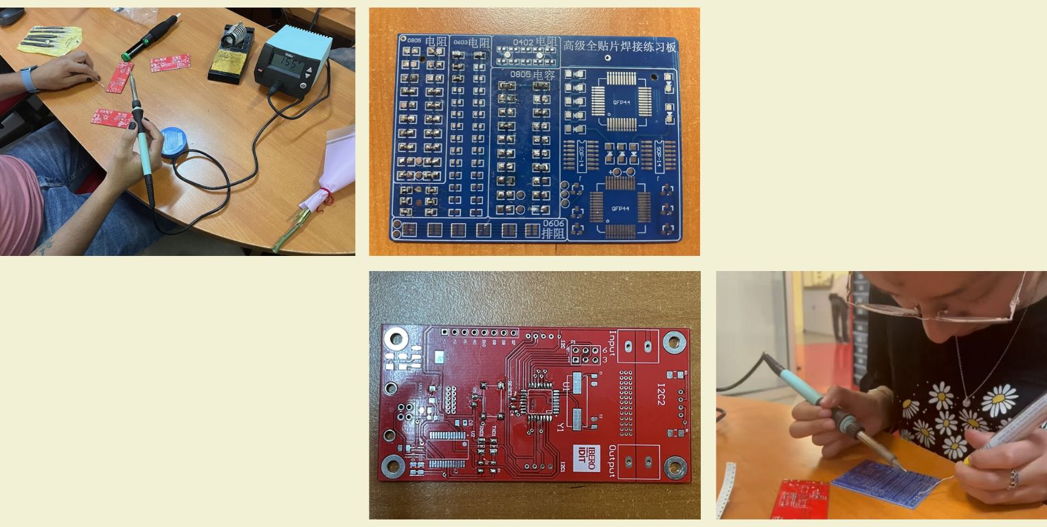
The truth is that the above sounds very nice, but for someone who had never done anything like this before, it was an unknown terrain, especially because I had never soldered before, let alone such small components. So the first thing I did was to ask for help to my advisor Alberto Blanco, who was kind enough to give me a quick lesson on the basics of soldering. Below, I share some photos of this class and my practices.
LET'S MAKE A PRINTED CIRCUIT BOARD!
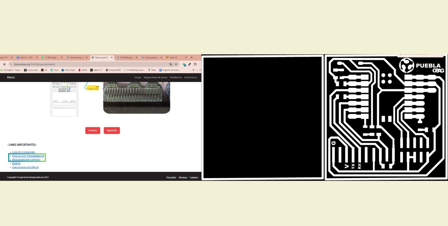
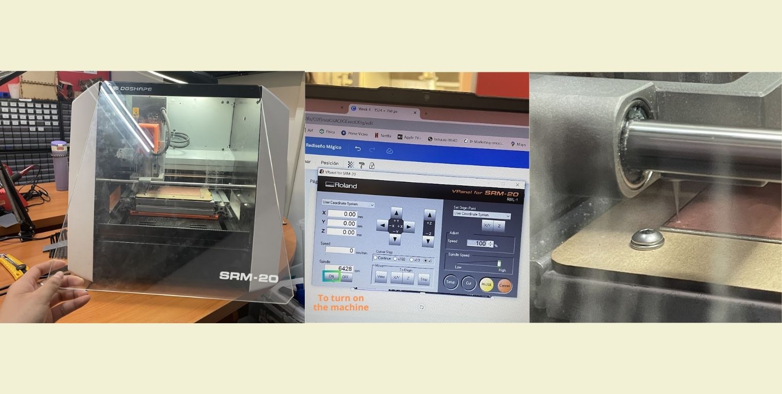
In FabLab Puebla we have a Mini Mill ROLAND SRM-20, in which we can translate digital designs into physical circuit boards, you can see more specific features of this machine in the following link. At the beginning we had a group class where we learned in a general way how to use the machine, however, to use it you need some previous steps, below, I list them for you.
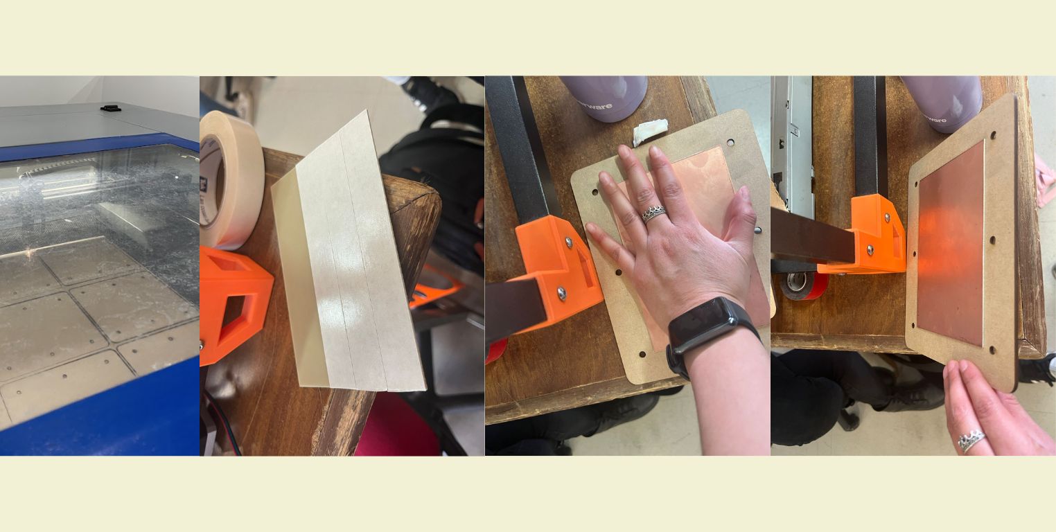
- Cut a sacrificial plate in MDF of 3mm. This can be done with laser cutting and is done because if we miscalibrate the machine tools we could damage the work table and with it the machine. And since we all depend on it, we don't have that luxury.
- To this sacrificial plate we glue with double-sided tape the copper plate on which we would cut the PCB, so that it would be firm and secure.
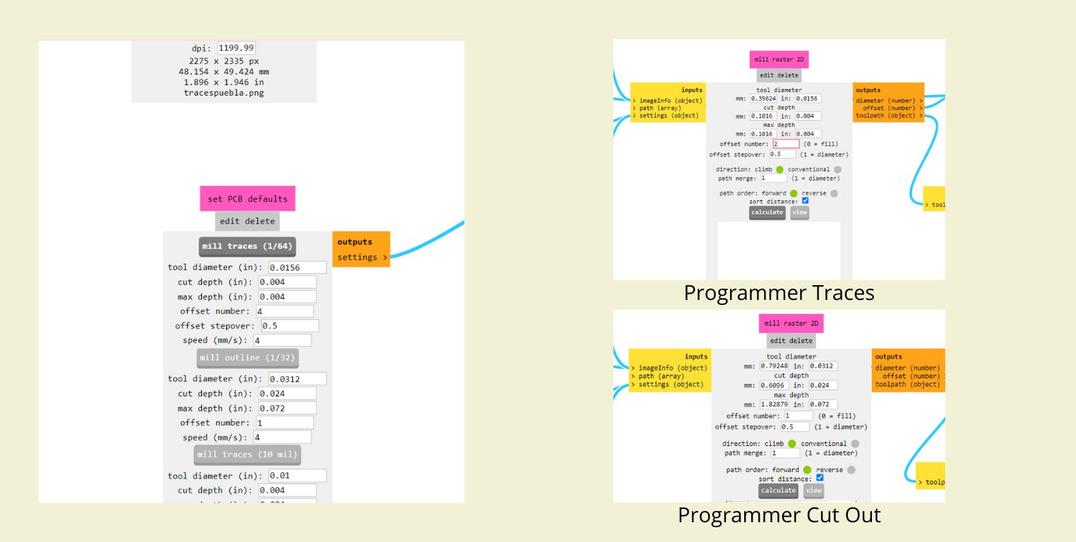
- We also need the files so that the machine can read them and then engrave and cut. For this in FabLab Puebla we use default files t hat our instructor Oliver Ochoa gave us and that you can find in the general page.
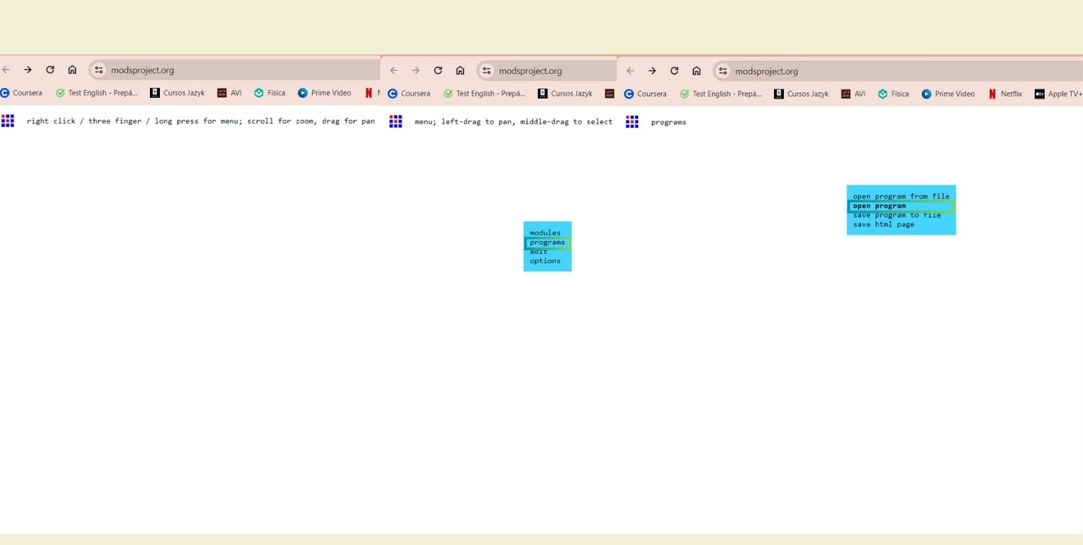
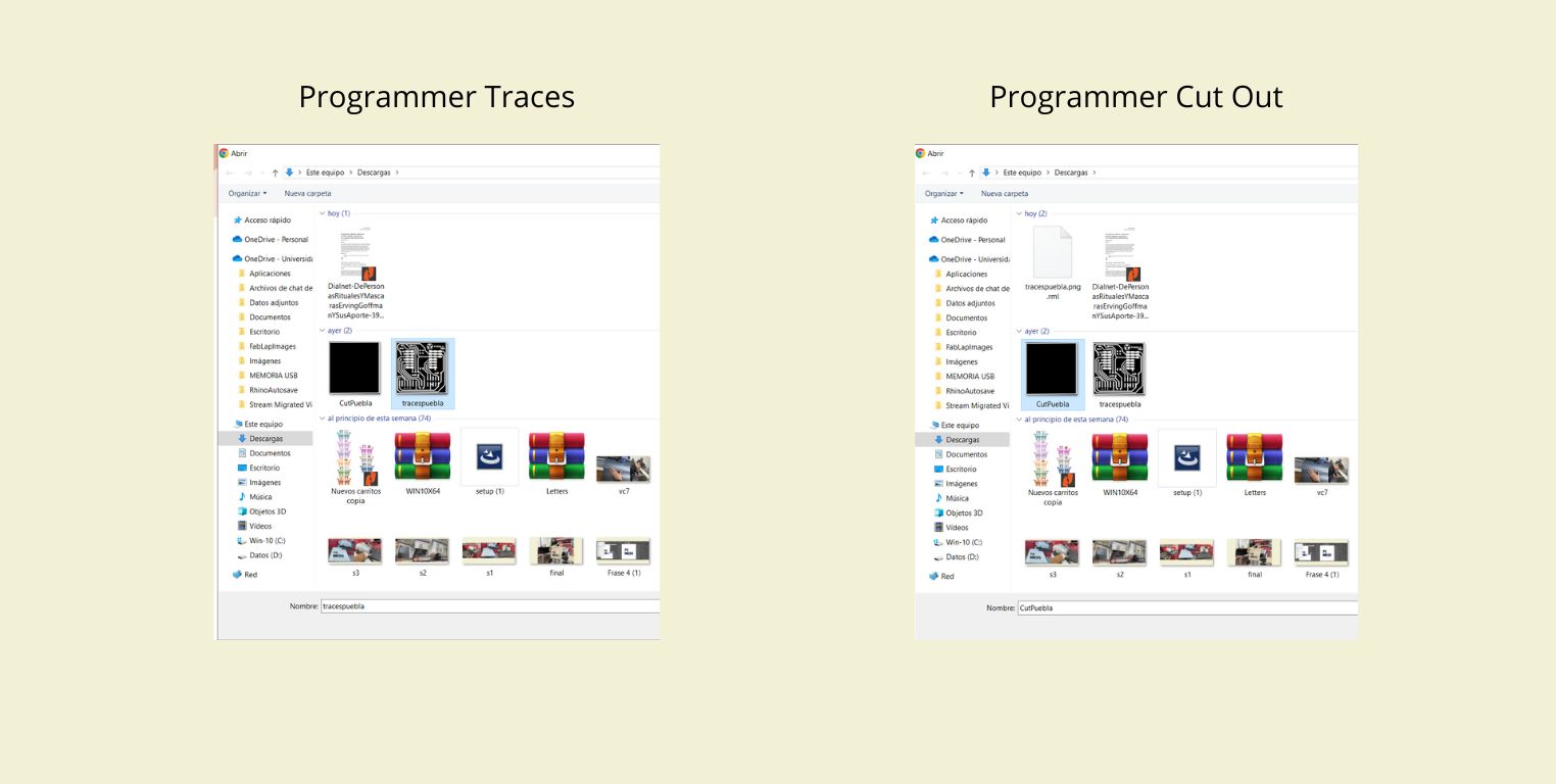
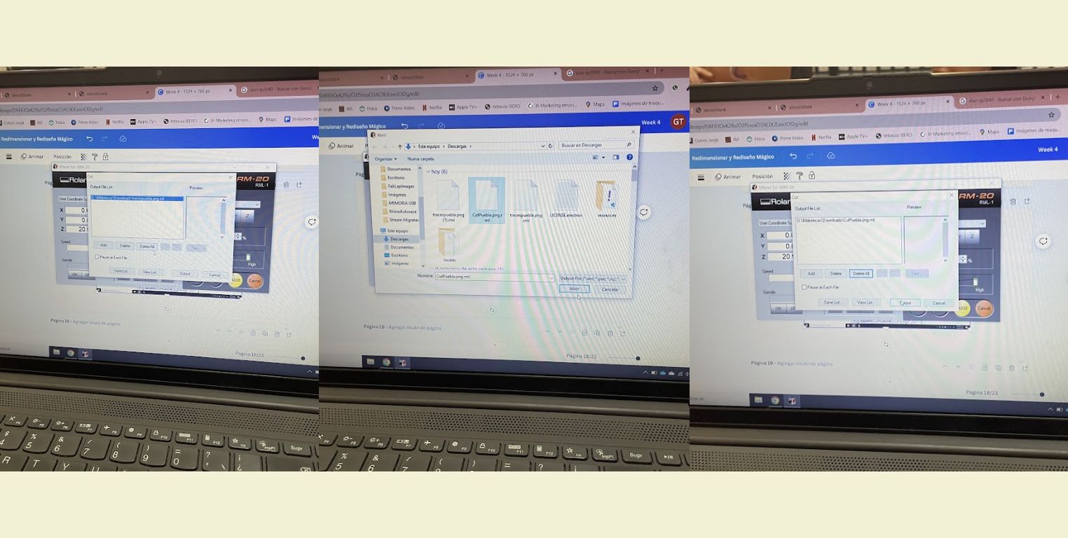
- What we did was to download "Programmer Traces" and "Programmer Cut Out". Then in MODS we made the cutting configuration for the machine we would use. Below, I will specify you the step by step of this process.
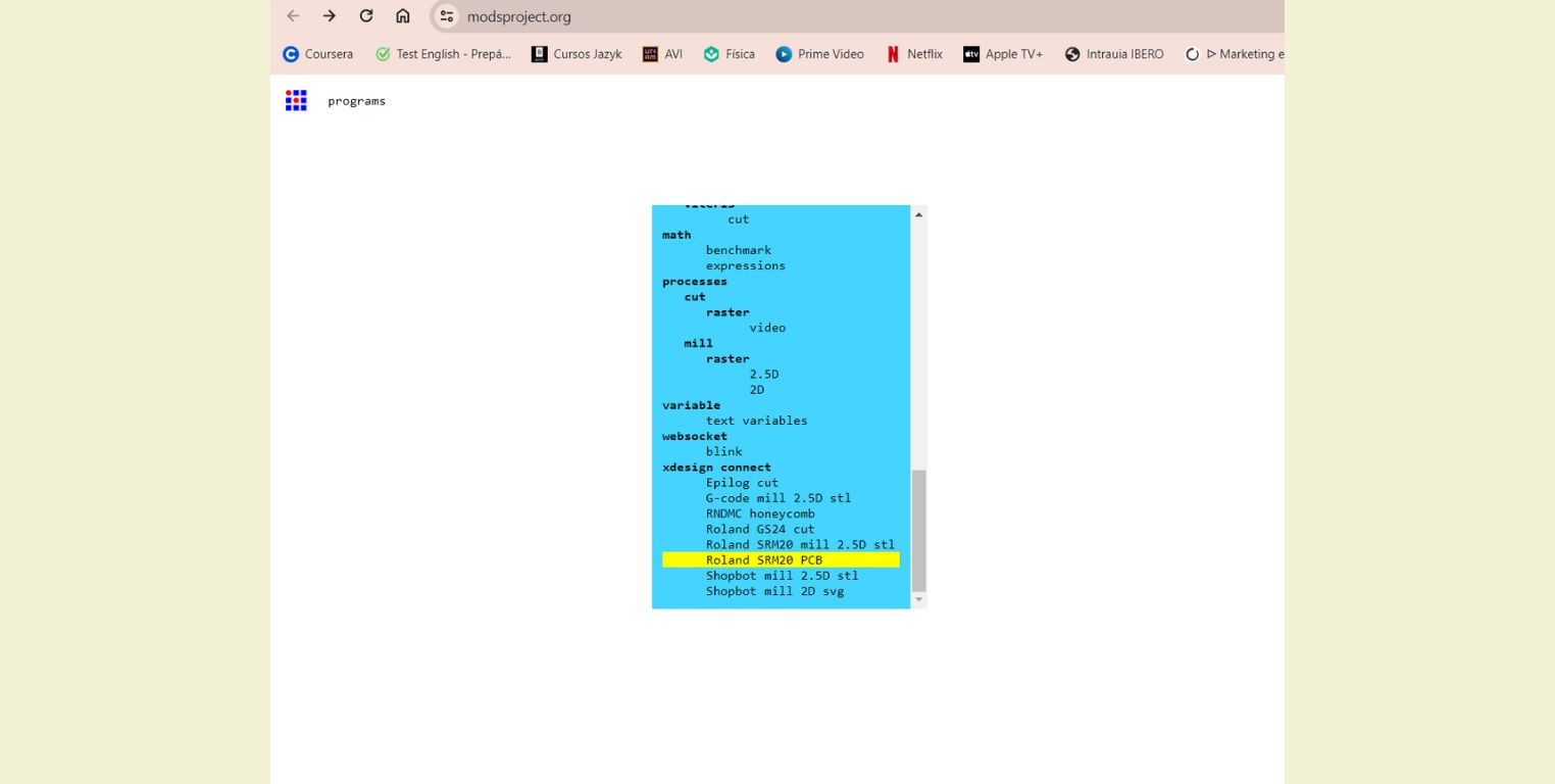
- When you open MODS nothing comes up, but just by right clicking on it, a blue box appears on which you select "Programs" and then "Open program".
- Then we select our machine, in this case it was the "Roland SRM20 PCB" and it was specified that we would be cutting a " 2D PCB".
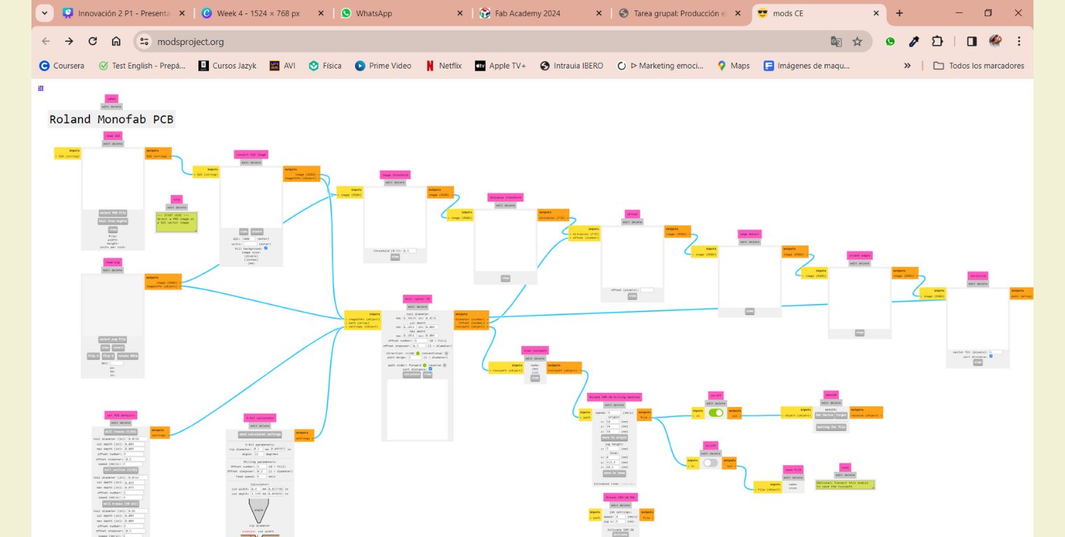
- This is an overview of MODS before we continue.
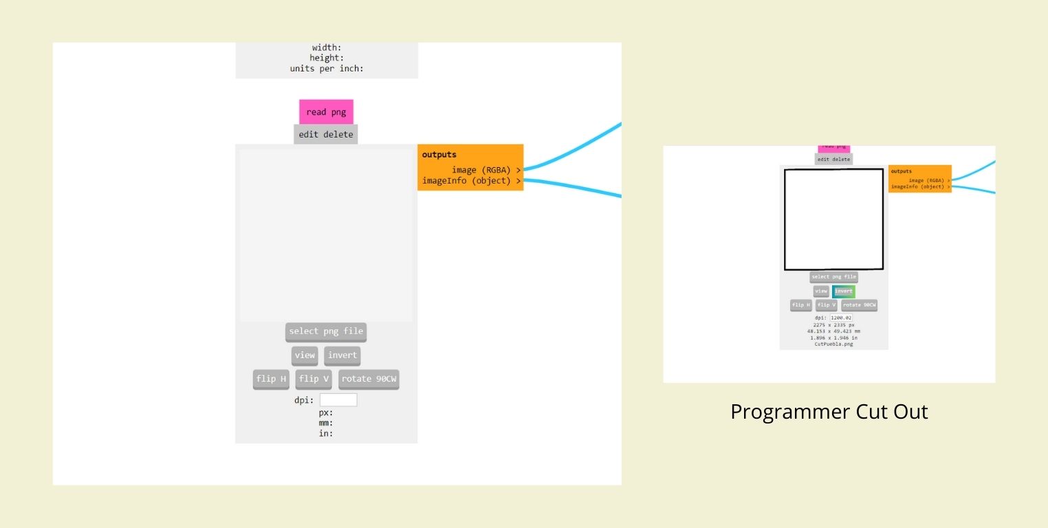
- In the "Read png" part we add the "Programmer Traces/ Programmer Cut Out" previously downloaded in the "Select png file" section. And in the case of the second, the color of the photo was inverted.
- In "Set PCB defaults" we clicked on "Mill traces (1/64)" and then in "Mill raster 2D" we changed the "Offset number" to 2 for engraving and 1 for cutting.
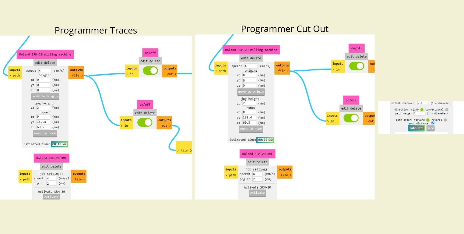
- Finally in "Roland SRM-20 milling machine" we change the "X, Y and Z" values to 0. (Below this section you can find an estimate of how long it will take for the machine to engrave or cut). Then we activate "On/off". Finally, click on "Calculate", doing this opens a tab with the drawing of the file that is downloaded and used by the machine.
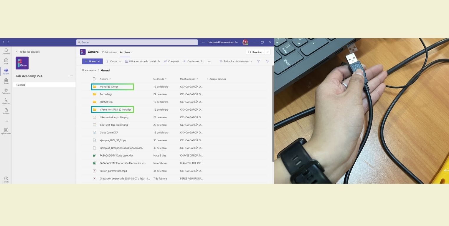
- In order to run the machine to cut our PCB's from our computers it was necessary to download the program and the respective drivers for our computers. The program only works when the machine is connected via USB to the laptop.
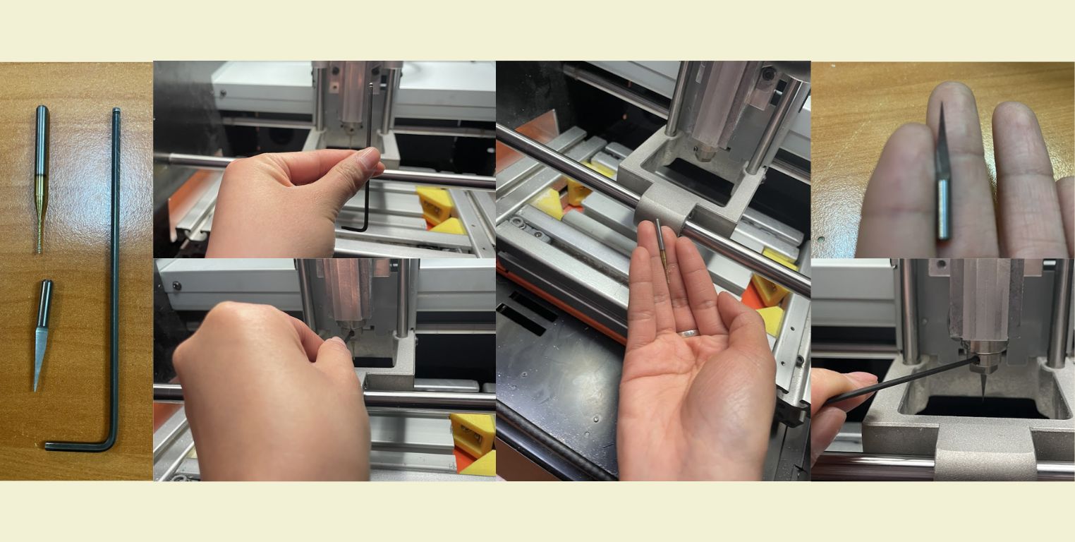
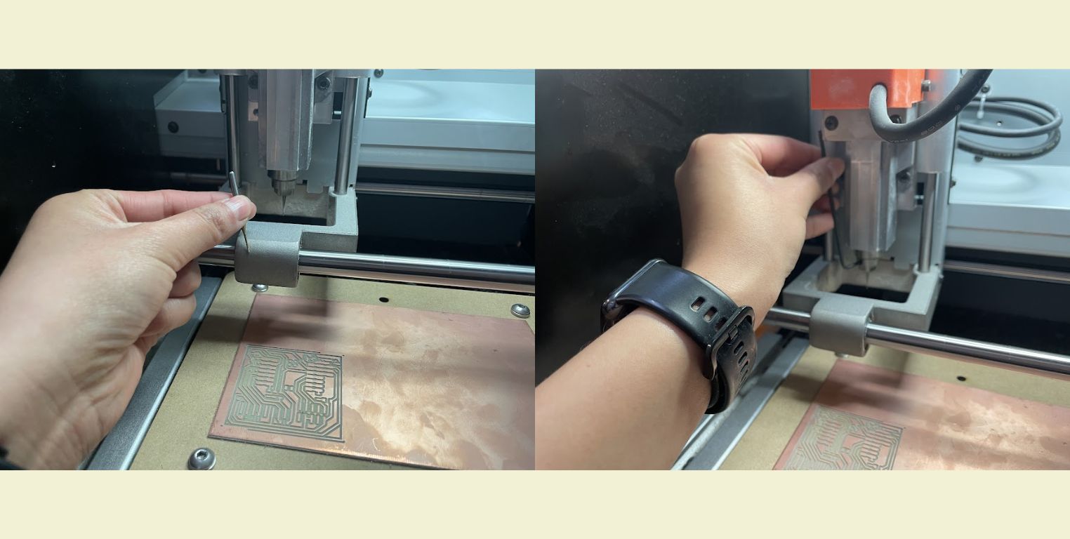
- When setting up the machine I changed the cutting tool to the engraving tool. For engraving we used a V-drill and for cutting we used a two-flute milling cutter. The first thing I did was to loosen the two-flute cutter (cutting tool) with the wrench and replace it with the V-drill (engraving tool), taking care that only the conical part protruded, because if it protruded more, the vibration could cause it to break. This was also done taking into account that it is important to engrave first and then cut, if it is done the other way around, the plate may move and the design may look bad.
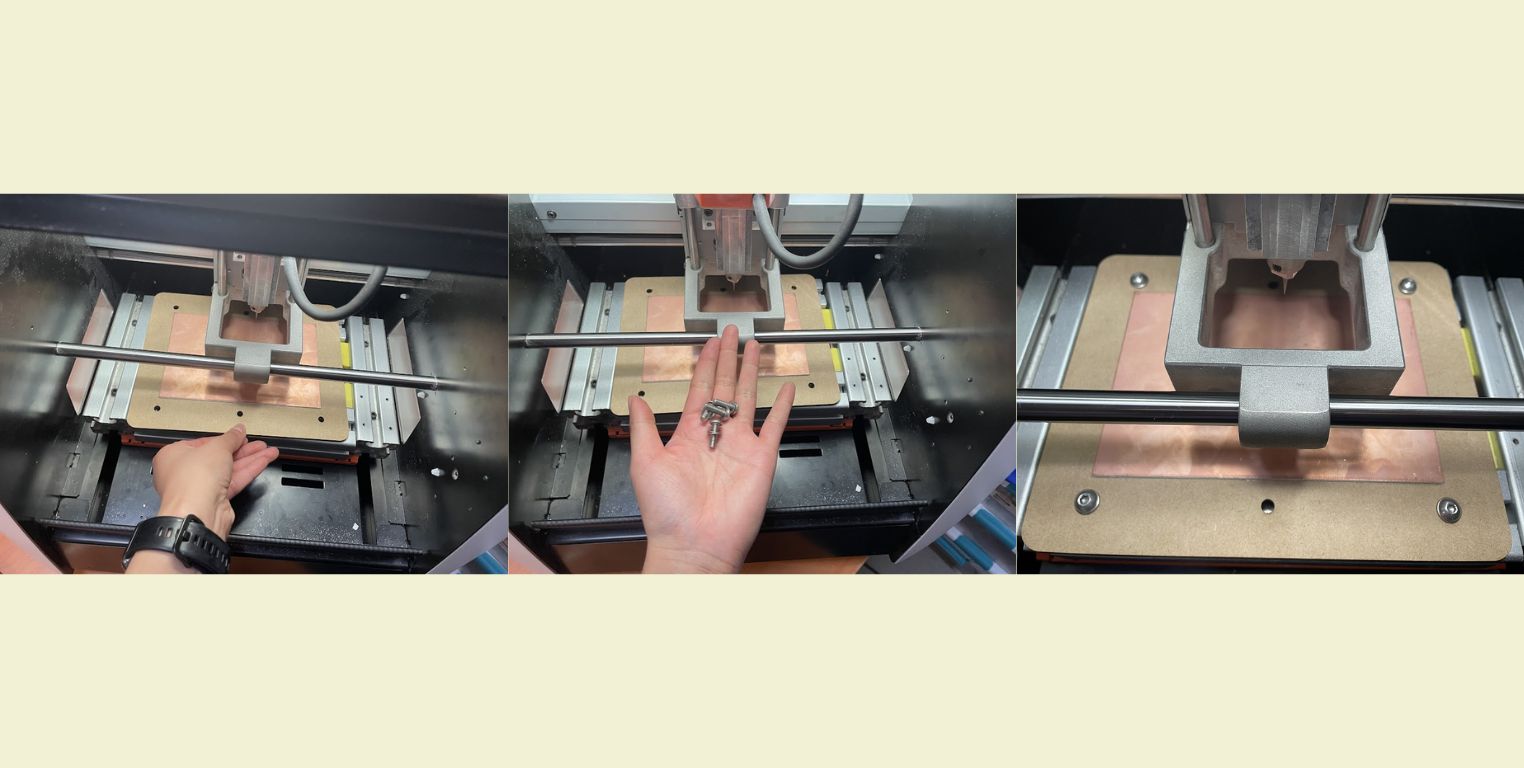
- The next thing was to position the sacrificial table with the copper plate attached on the worktable and we adjusted it so that it would not move.
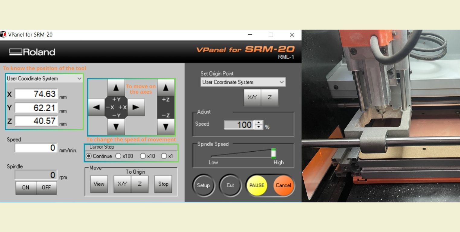
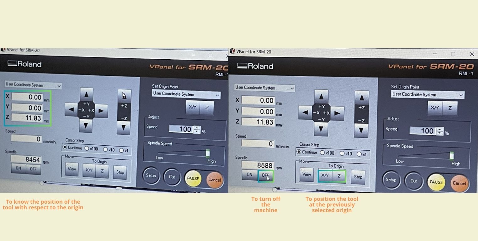
- With "Continue" and a lot of caution I started to move the tool in X, Y and Z to the lower right corner to position there the origin of the start of the cutting and engraving.
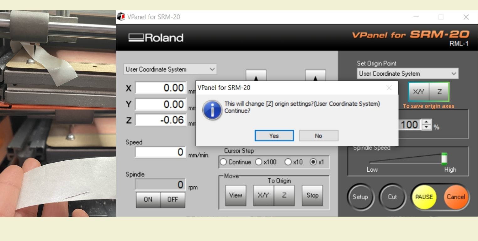
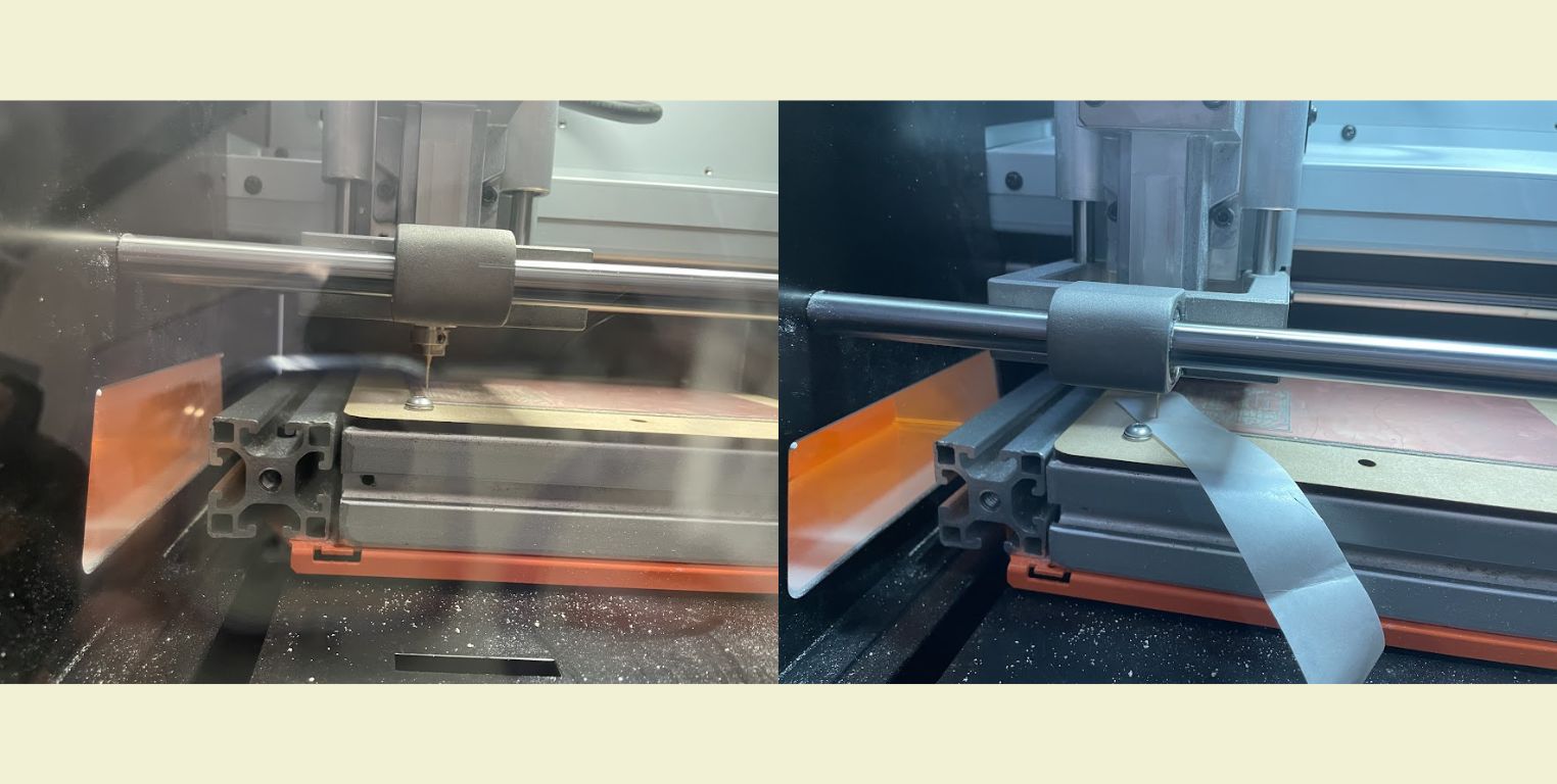
- Once close I used the paper method to verify that the tool was already touching the surface of my material without any problem. With "x1" I moved down in Z little by little until the paper under the tool was no longer moving and I could only pull it out by tearing it. At that point I went down a little more Z and marked the origin on ALL 3 AXES. This is super important because the first time I tried to cut I could not cut because I had not marked the Z origin, and the machine started moving, but not cutting, so it is important to check.
- To verify that it was cutting I closed the machine and clicked "ON".
- Once the tool started roughing the material at the origin I raised the tool in Z with "Continue" and clicked "OFF".
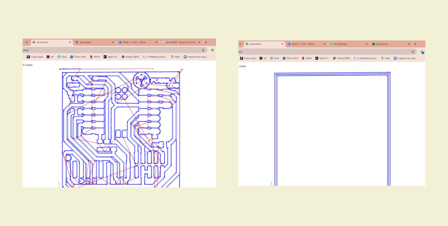
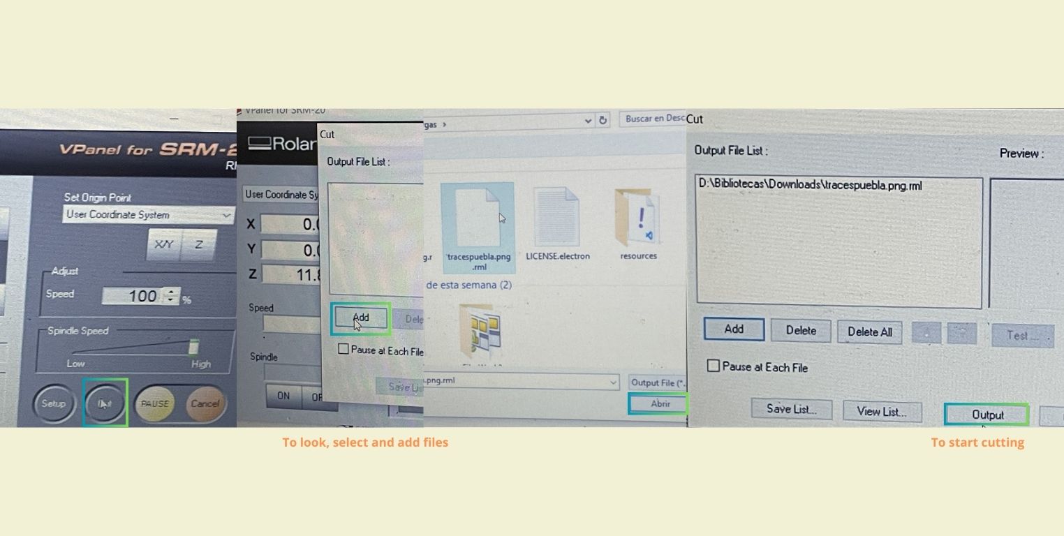
- It was time to load the file for cutting. For this in the "Cut" part it opened a tab and in "Add" it allowed me to select the file downloaded from MODS "tracespuebla.png.rml". Once ready I clicked on "Output" so that the machine would start working on the engraving.
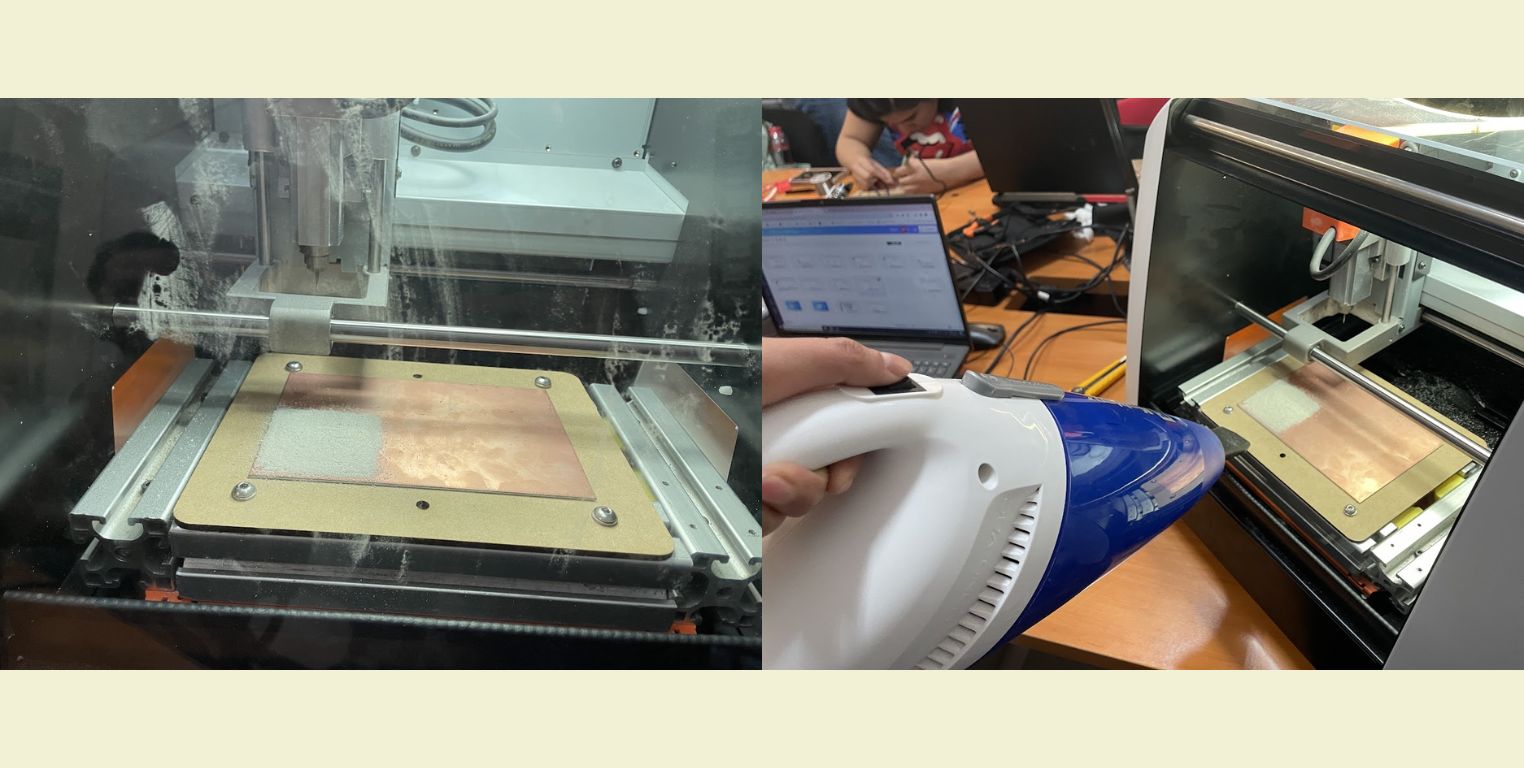
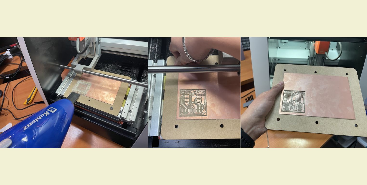
- When it finished engraving I raised the tool in Z and opened to vacuum all the dust with the help of a hand vacuum cleaner.
- Once the work area was free of dust, I replaced the engraving tool with the cutting cutter.
- I positioned the tool again at the origin I had marked for X and Y, but not for Z. In this axis I checked again millimetrically with the paper technique that it was perfectly touching the surface.
- Then I deleted the previous file and added the "CutPuebla.png.rml" file. With "Output" it started to run.
- As soon as it finished cutting I again made use of the vacuum cleaner to absorb the dust left by the cut and removed my sacrificial board along with my already cut PCB.
LET'S GO SOLDER A PCB !
The first step was to get all the necessary parts, and for that we took into account the base photo and guide provided by FabLab Puebla, and this consisted of 1 XIAO-RP2024, 3 LED's, 7 resistors (in my case I used 1.2 and 1.3 K Ohms), 20 male and female pins, plus a button.
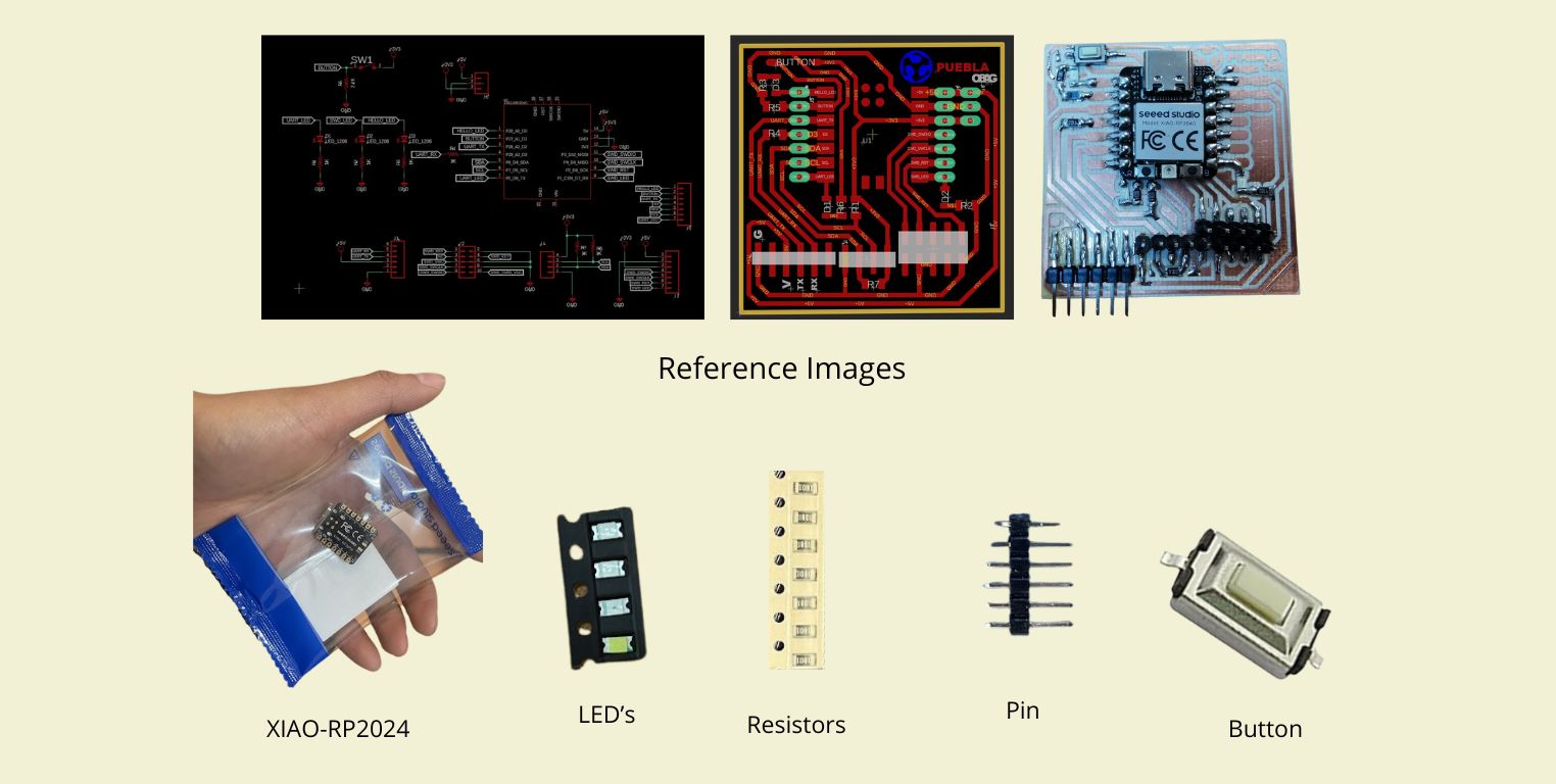
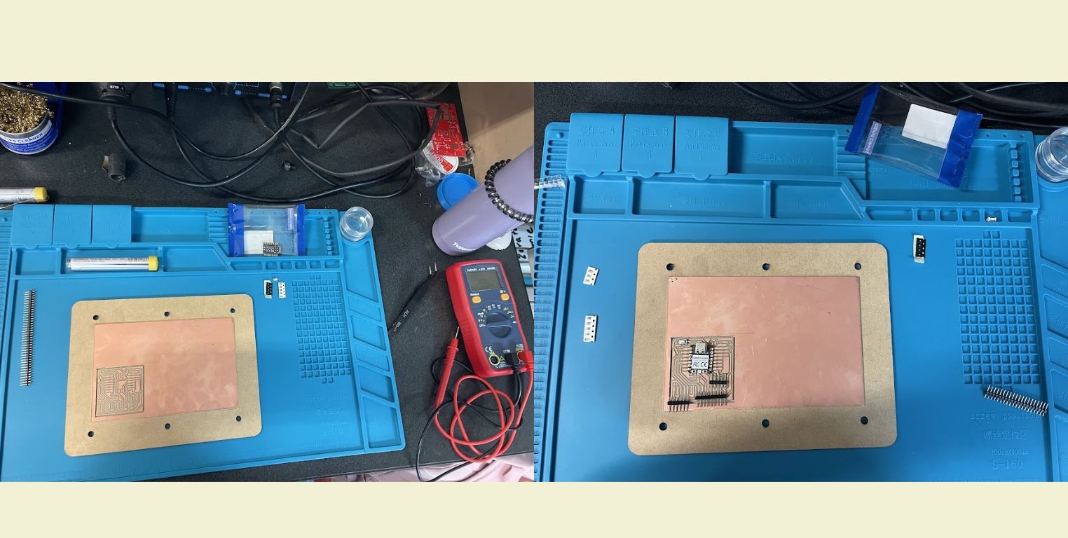
Then in my work area I started by arranging the pieces, to take into account the spaces and make sure I didn't miss anything before starting and everything went faster. The blue mat was a great help for this, because it did not allow my board to move and also the small compartments it has are ideal to avoid losing the smallest components.
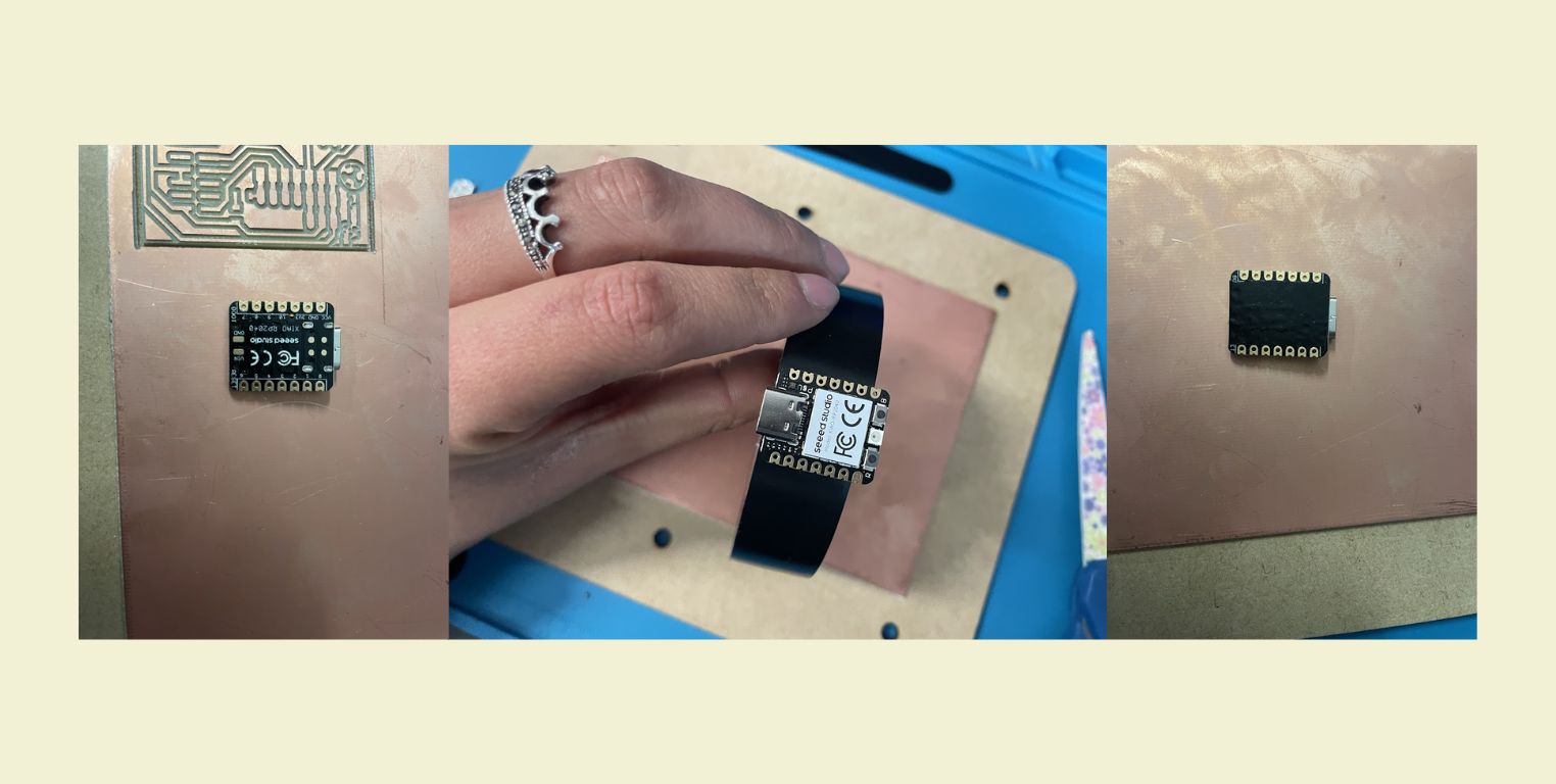
Before starting, I put insulating tape on the back of the XIAO. This was to prevent solder from getting on the bottom and burning this component.
To solder everything I started with the smaller components from the center outwards, then I went between LED's and resistors, then I went to the pins and finished with the button and the XIAO. But first I did some soldering tests on my board because where I had been practicing was a somewhat different terrain since on copper all the solder can stick. So I had to be very areful when soldering not to use more solder than I should, although later I had a problem with that, because I didn't want to use so much solder when programming the PCB, it didn't work as it should. So from now on I make the note that you should not use too little solder, but the necessary. In addition, before starting I also had to bend some pins at 90° to be able to solder them to the board, and for this it is better to solder all the pins that go together at the same time, that way it is easier. Here are some clips where I show you the process.
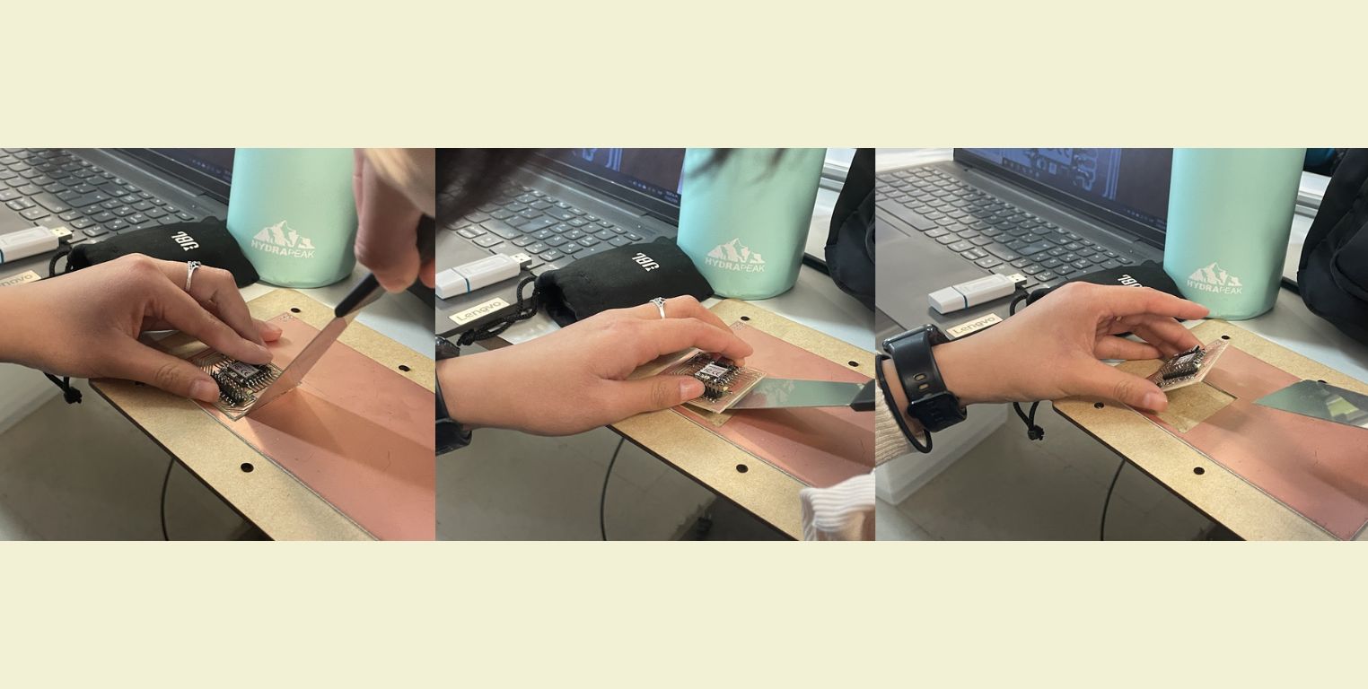
One super important thing is to remove the PCB from the copper board. This is actually easier if done before soldering any components. It didn't take me more than 5 minutes to do this step, but there was a chance that my components would come off and I would have to waste time soldering again.
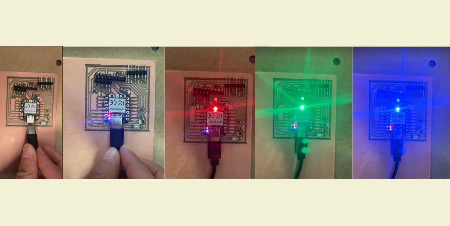
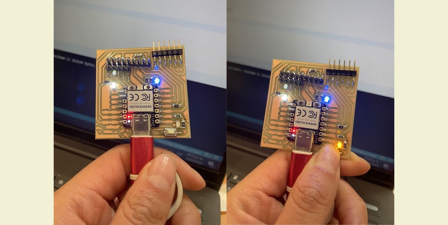
Once I got my hands on the ready PCB I plugged it in to verify that it was working properly and had not burned up the XIAO. At first it starts up with the default program.
Let's go to program a PCB!
Then for everyone to program their PCB we used Arduino and the following code provided by our consultant Huber Giron. This code makes 2 LED's blink and the third one only turns on when the button is pressed.
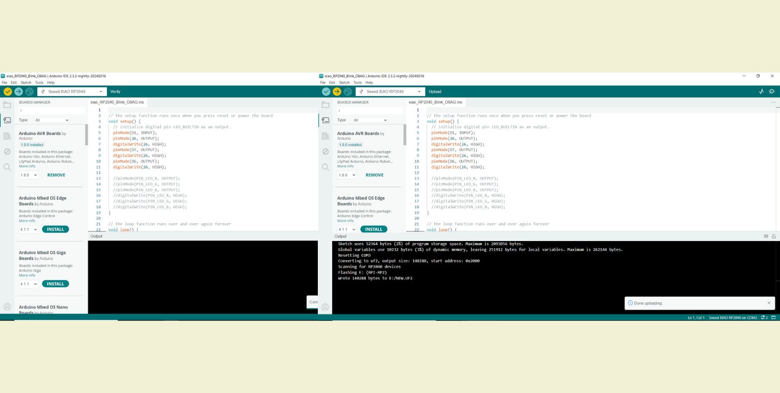
The first step was to download Arduino. This is a free and open source software that you can easily. And once downloaded so that Arduino could run the program on my PCB, I had to indicate the name of the XIAO. For this on the internet I searched for the name of the XIAO and from a page I got the link corresponding to Arduino. In the same page is the step by step on how to do it.
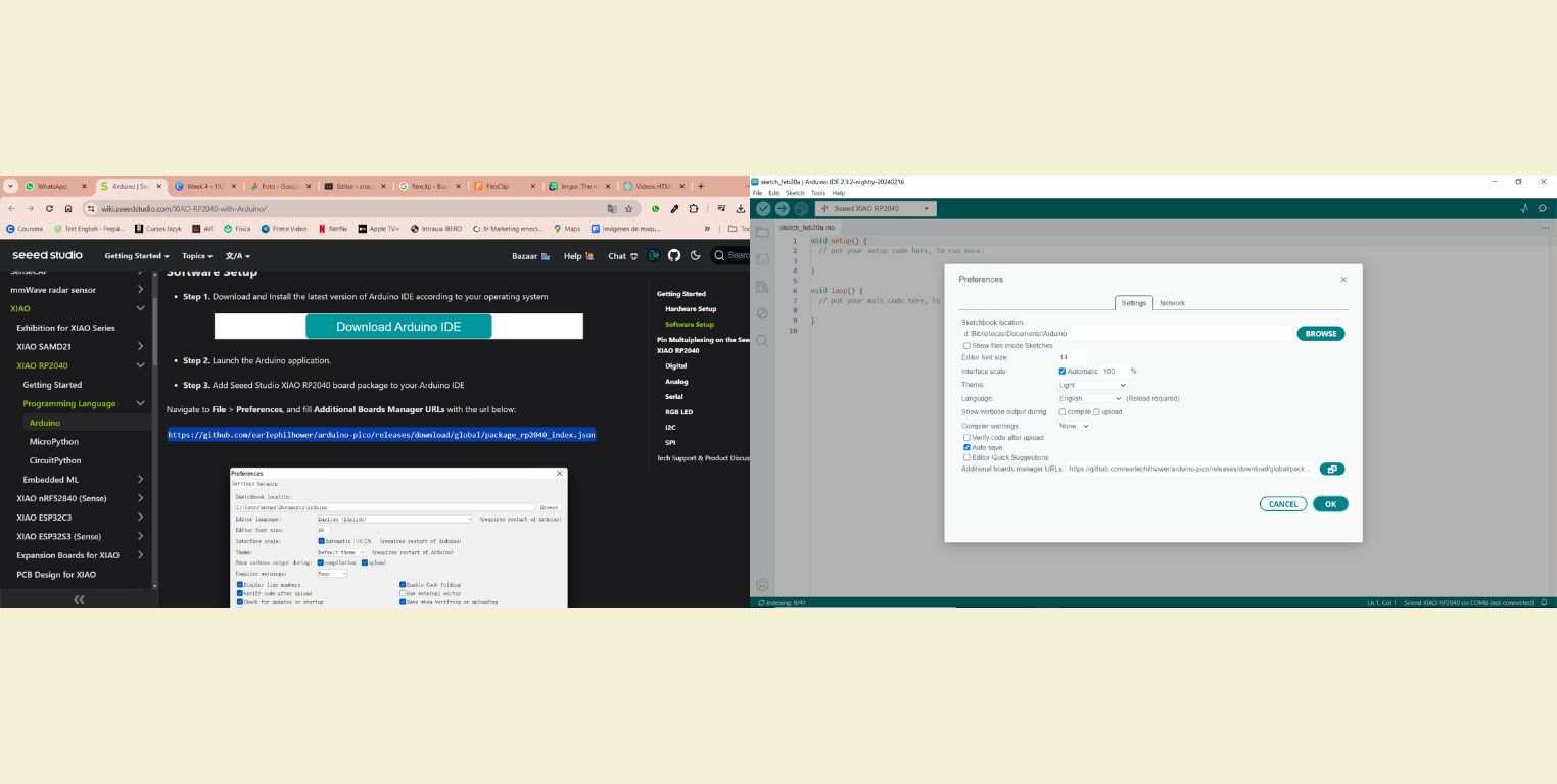
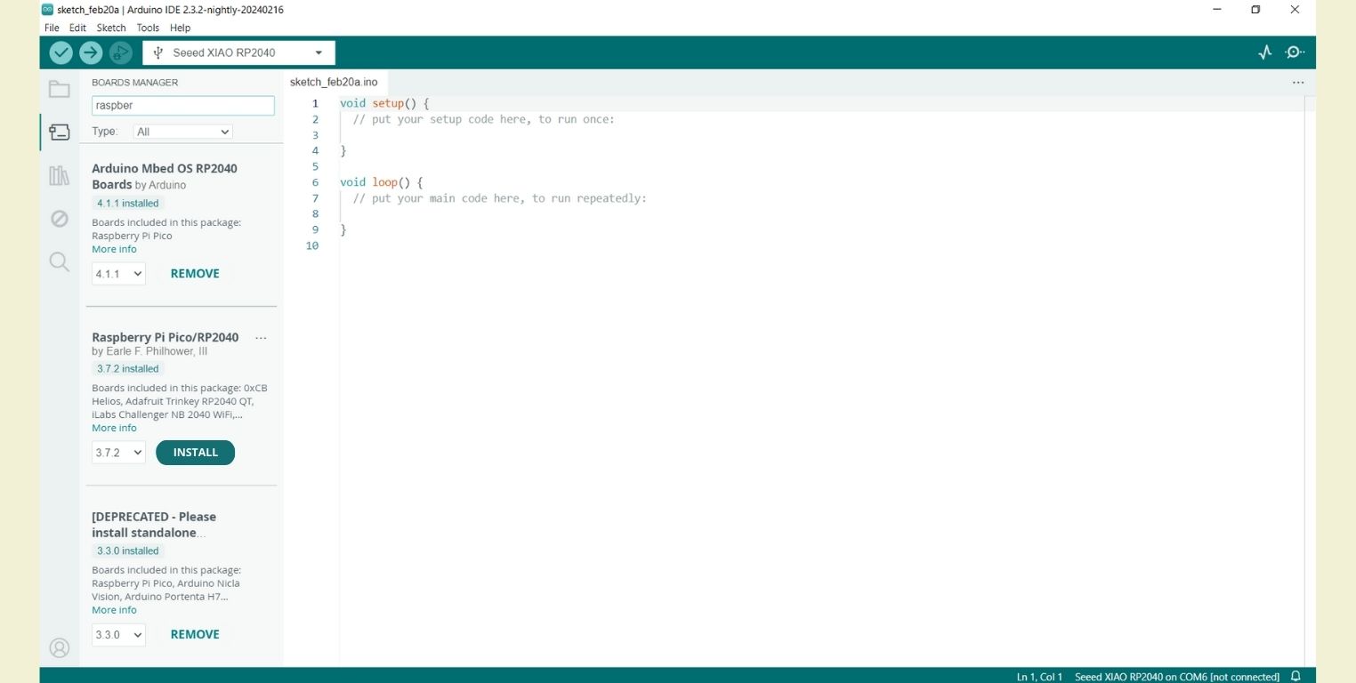
Then I downloaded the Board Manager corresponding to the XIAO. For these I searched for Raspberry Pi Pico/RP2024 and installed the 3.7.2 version.
Then I was able to open from Arduino the code that we had been provided. And the next thing was to connect a C-type cable to the laptop and look for it in the Arduino ports. It has to be connected to detect the port, and the cable has to output the communication signal. At first I was using the cable to charge my headphones and it didn't detect it because it didn't have the aforementioned feature, however, cell phone chargers and iPad chargers work without a problem.
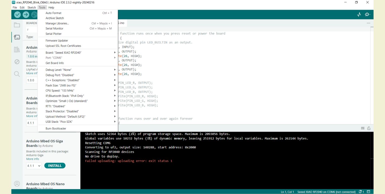
Once the port is detected, it is verified in the upper left corner. And then the code is sent to the connected PCB. If everything went well, 2 LED's blink immediately and the third one only turns on when the button is pressed. This last step didn't work for me because of problems with my soldering, because at the end I failed to put more solder on the XIAO and on one LED. But after verifying this with the help of a multimeter and more solder it finally worked.
Conclusion
This practice was challenging in many ways, but, all in all, it was a practice that I really enjoyed doing, as it taught me to improve skills quickly, although I think this is partly because I really like to do manual things, and more so if they are prototypes like this week's deliverable.
But this is also relevant because the soldering does not have to be 100% perfect in a prototype, there are more important things like getting it to work, although the technique can help us not to burn the components, it is also important to advance and verify to have time to correct if necessary. To verify it is always good to have a multimeter by your side, even from the moment you start soldering until you program it.