13. Molding & Casting
What is molding?
It is the process of creating a mold that represents the empty or negative element of the thing that we wish to create. A mold is a cavity into which casting materials such as polymers, metals, and resins are poured or injected and then cure to produce a product. Molds come in a variety of materials, including plastic, silicon, sand, and metal. Injection molding involves the use of metal molds. In certain processes, a direct mold is created using CNC, while in others, a positive element is pressed or put within the mold to form the negative of the character shapes of the object to be made or replicated.
What is casting?
Casting is a manufacturing method in which a liquid substance is typically poured into a mold with a hollow hole of the required shape and then allowed to harden. The solidified portion, also known as a casting, is expelled or broken out of the mold to finish the process. Casting materials are often metals or other time-setting materials that harden after combining two or more components; examples include epoxy, concrete, plaster, and clay. Casting is most commonly used to create intricate forms that would be impossible or prohibitively expensive to produce using other procedures.
Group Assignment
Visit our group task by clicking on the button below.
What did I do this week?
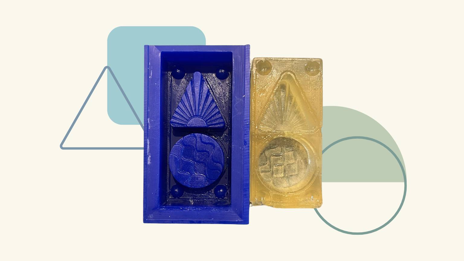
I decided to create a mold based on three of the elements of my final project. Also, based on the designs I made in week 02, in the 2D Design section.
This was my base:

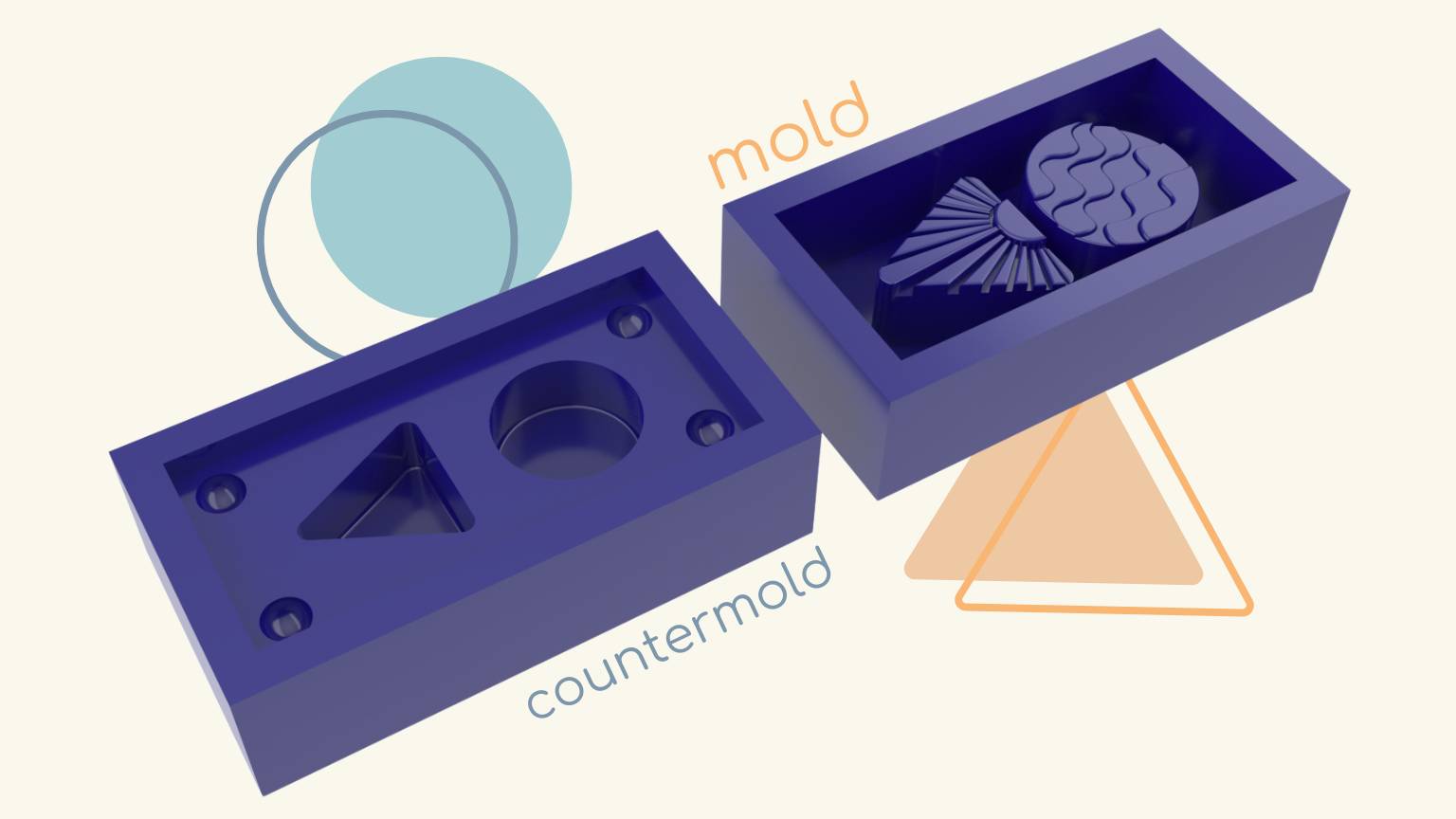
Mold Design
I designed the mold in Rhino 7.
Steps:
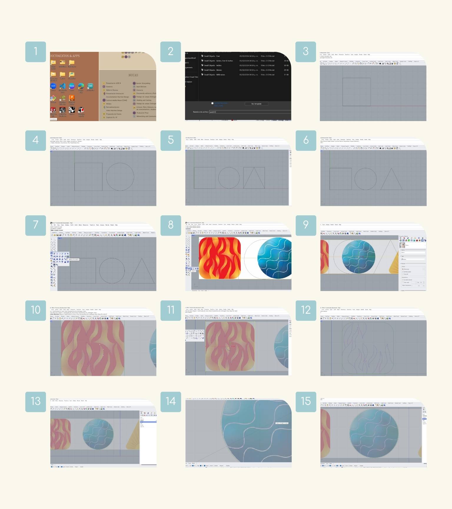
Fist Idea:
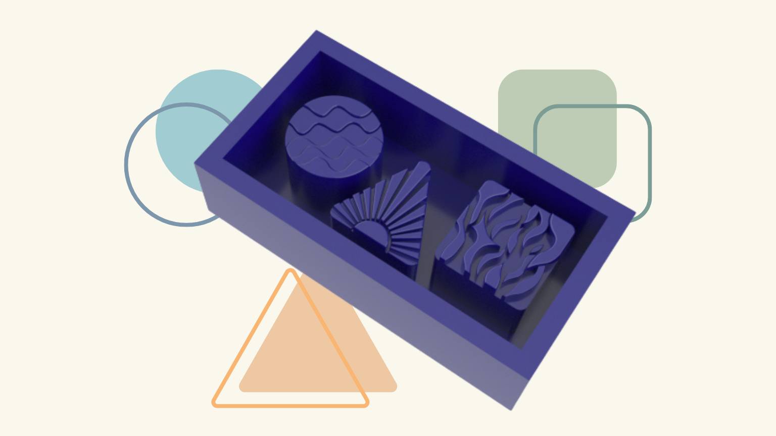
Final Result:
Preparing the cut
Recap
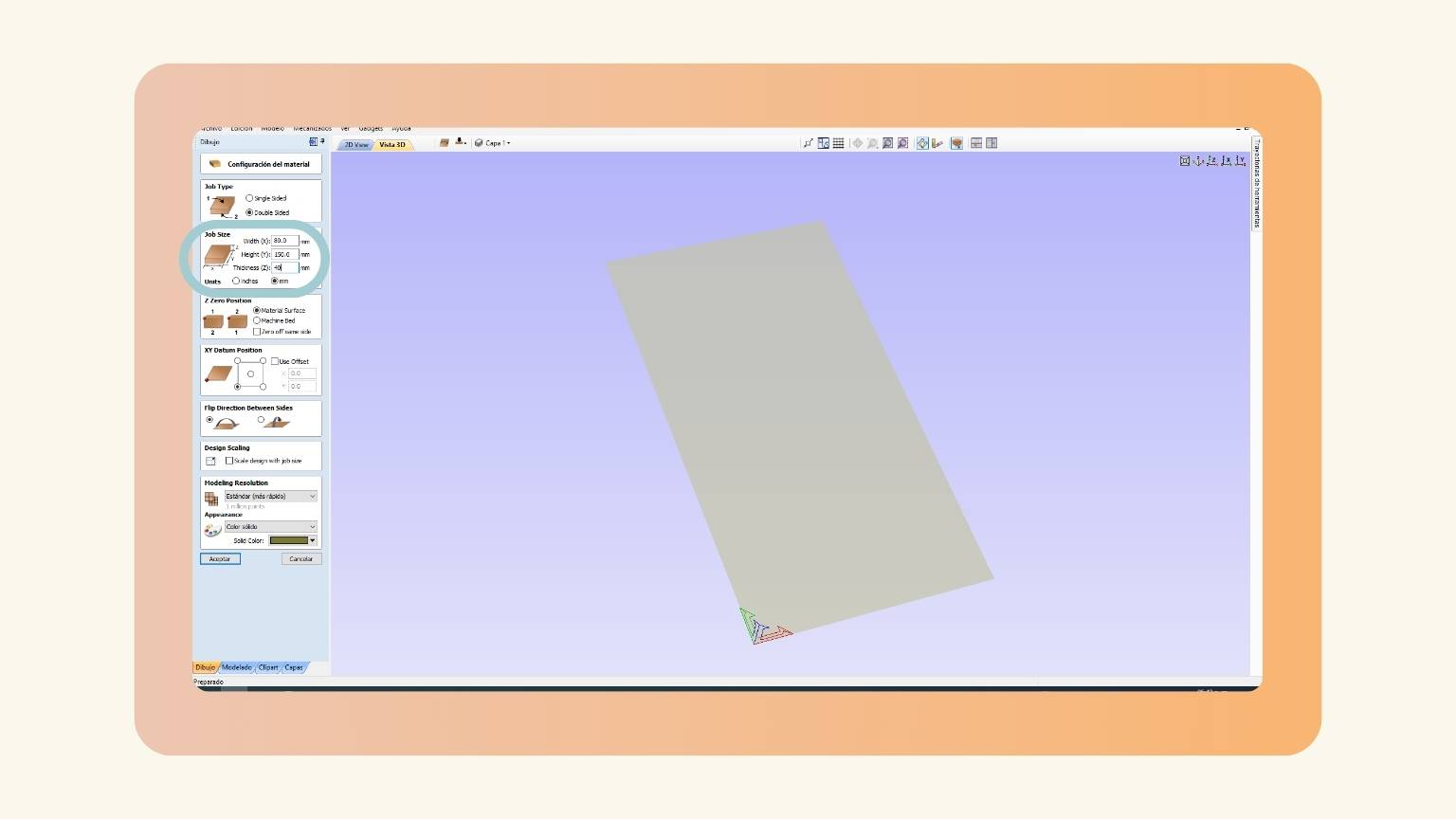
To prepare the control software, I used...
VCarve
An effortless milling and engraving software solution.
VCarve Time
Steps:
- First, I put the measurement of the material, in this case, 150 mm of width, 80 mm of height, and a thickness of 40 mm.
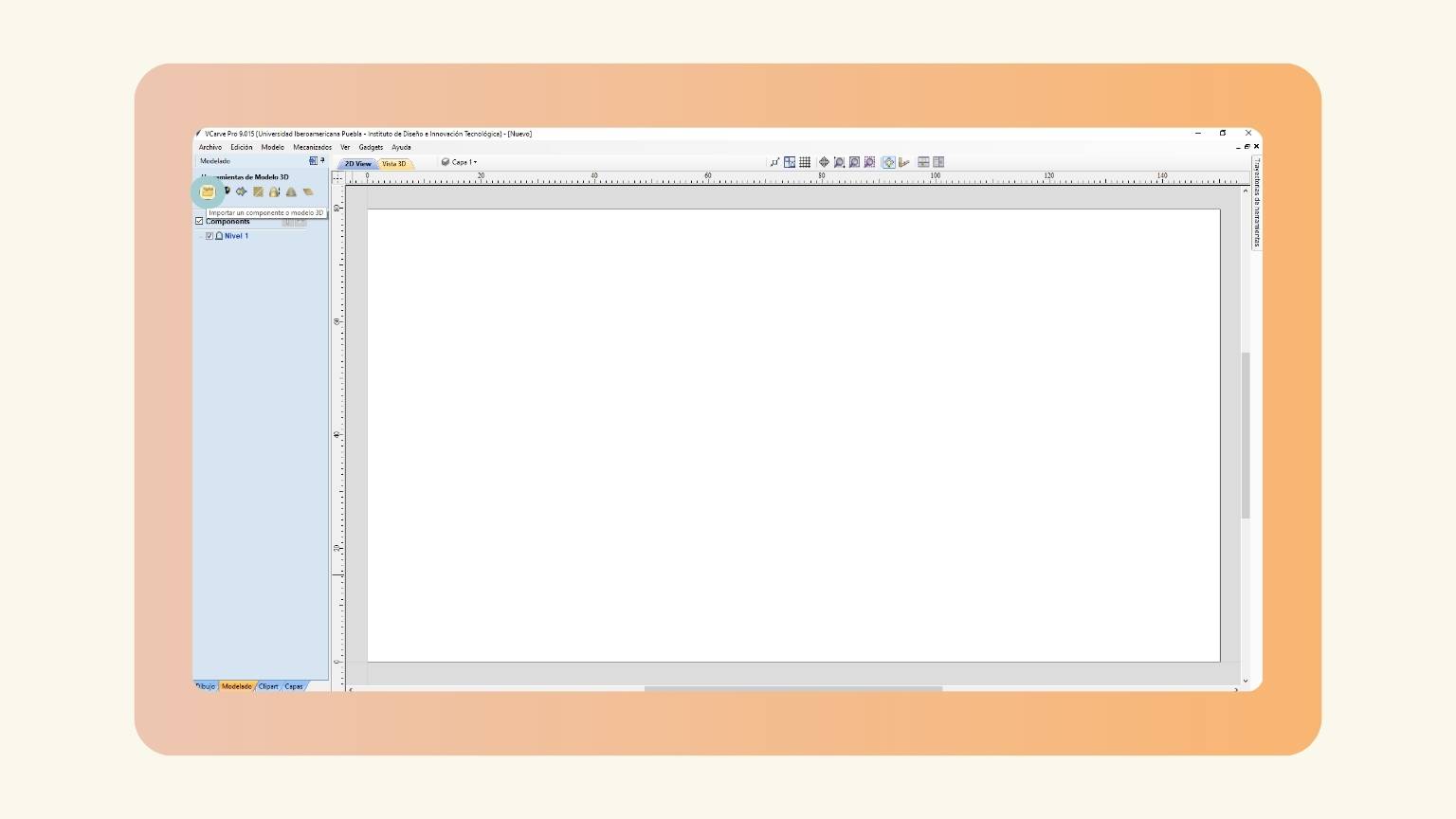
- Then, I opened the modeling section.
- I selected the ‘Import a 3Dmoldel or component’ option.
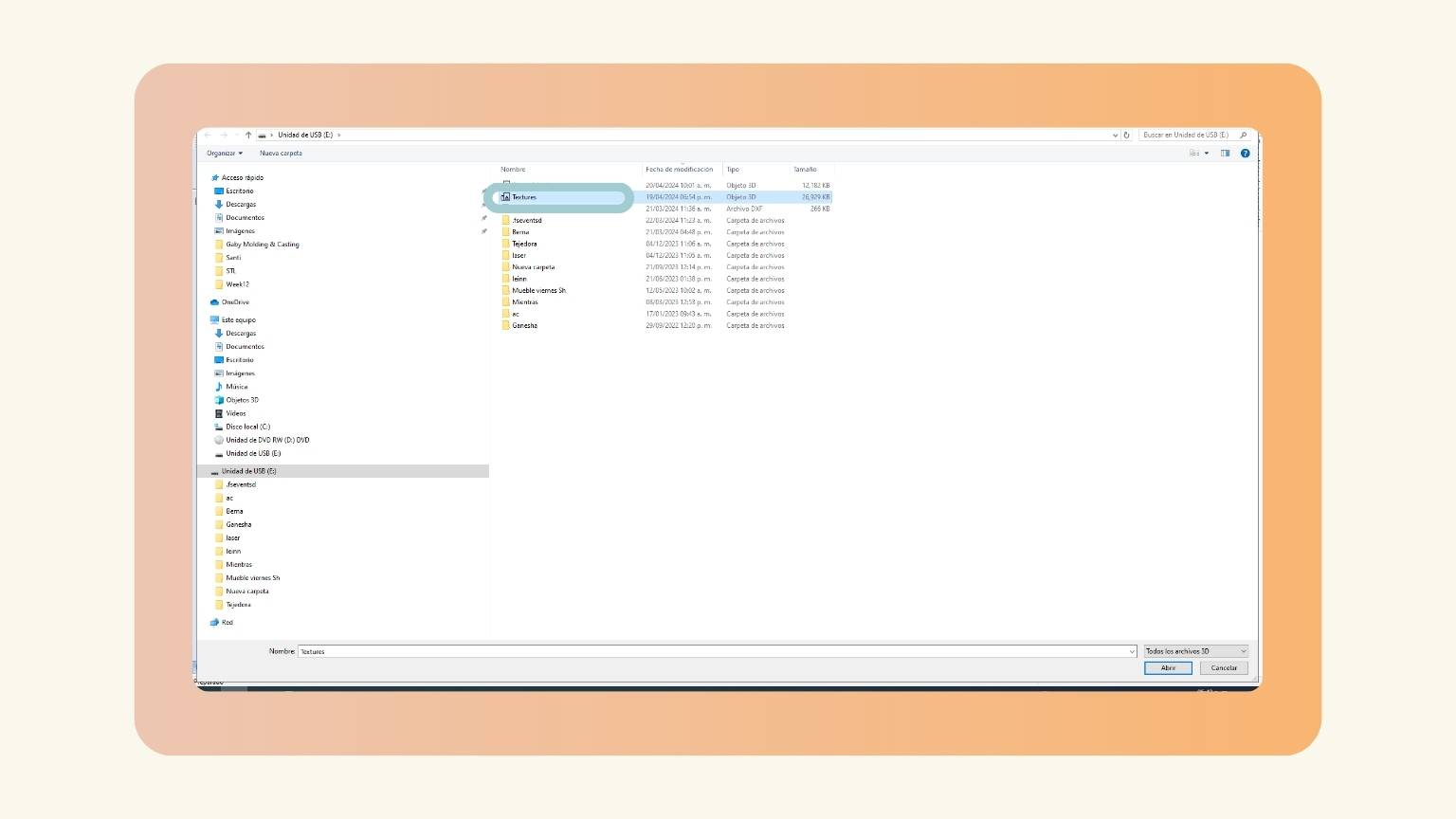
- I uploaded my file.
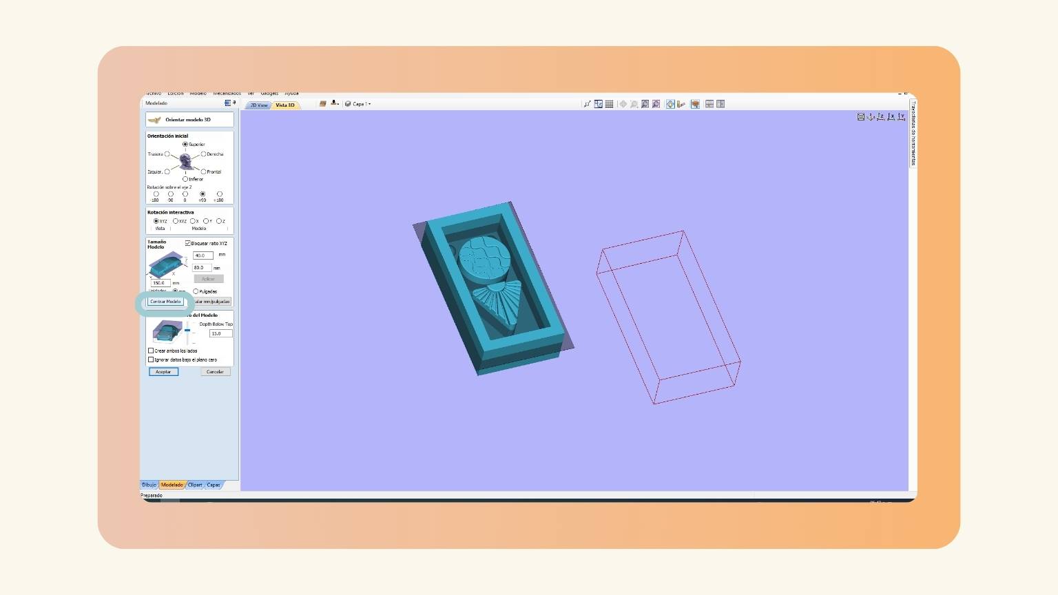
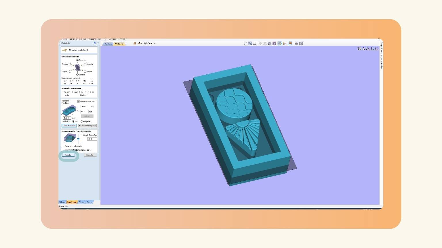
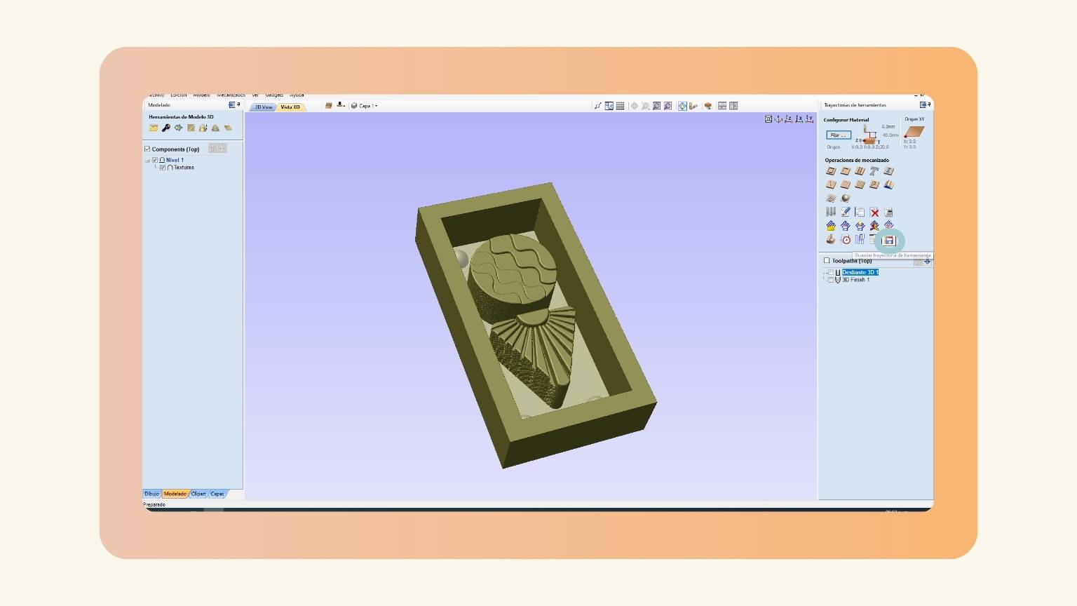
- When my model opened, I changed the orientation of the piece to ‘+90’.
- Then I centered my model.
- And when the model was in center, I pressed ‘Accept’.
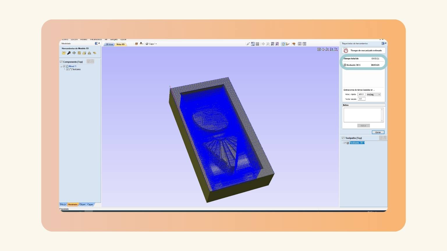
- The model looked like that:
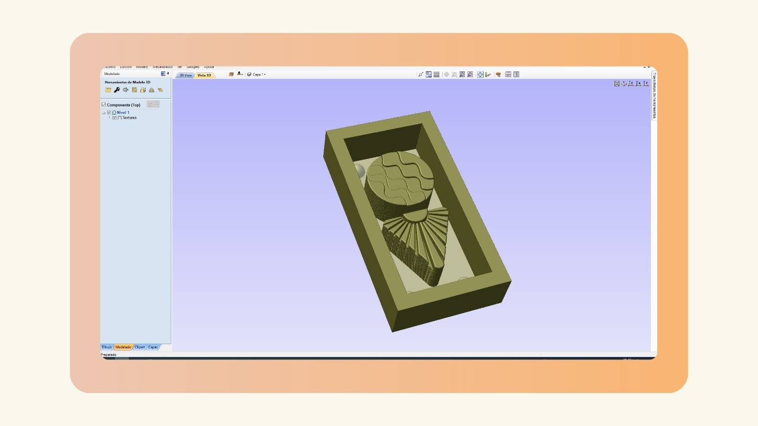
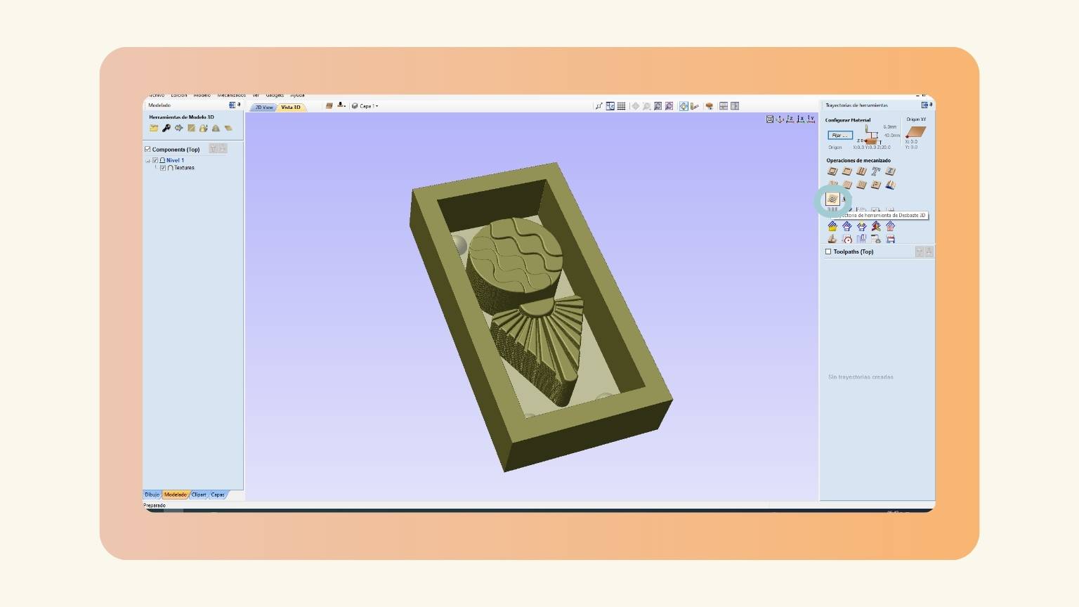
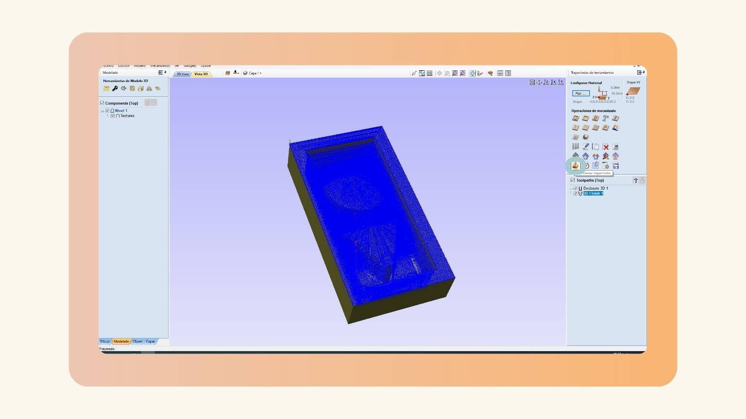
- I went to the ‘Tools paths’ section and pressed the ‘3D roughing tool path’ option.
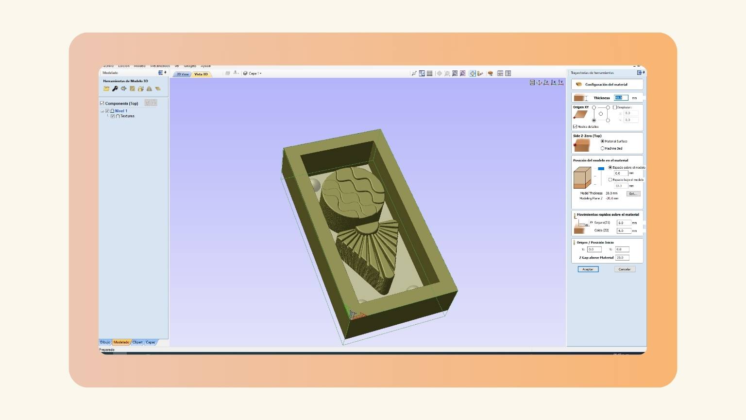
- Next, I made sure that the material configuration was correct.
- Then, I saw the tool and your configuration. And I saw that it was correct, so I pressed ‘Accept’.
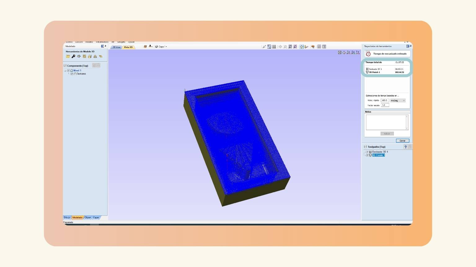
- I previsualized the trajectory of the tool.
- I saw the estimated machine time.
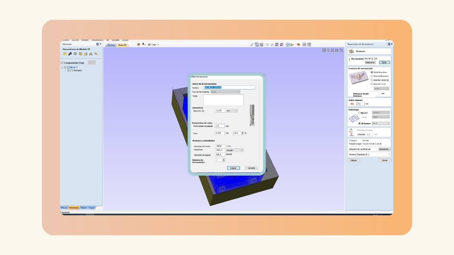
- So, I came back to the configuration of the tool to increase the percentage of the step to reduce the time of the machine.
- I saw that the time decreased.
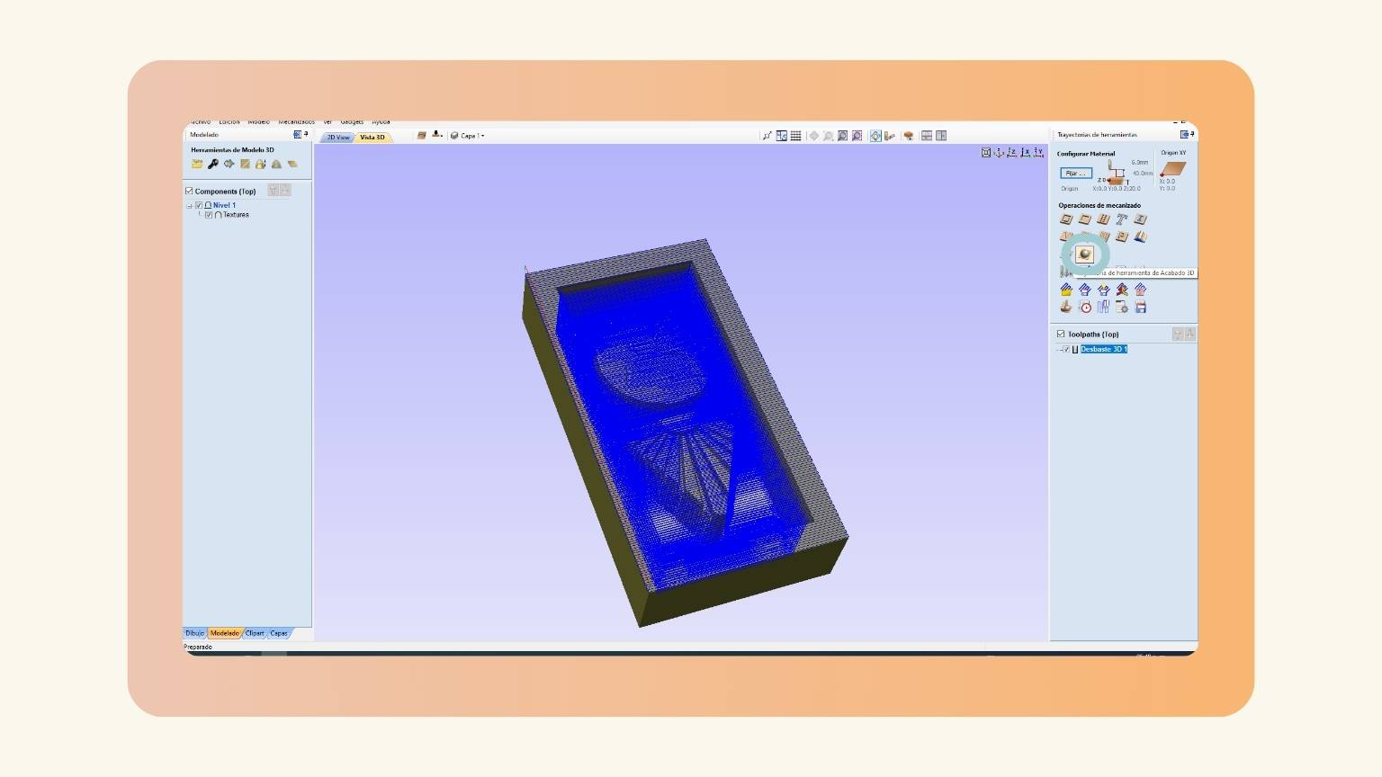
- Then, I pressed the ‘3D finishing tool’ option.
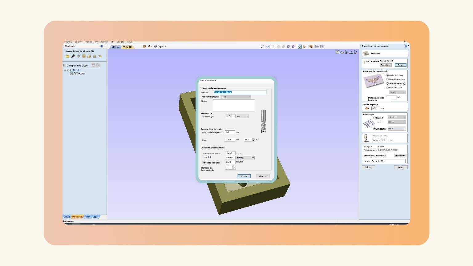
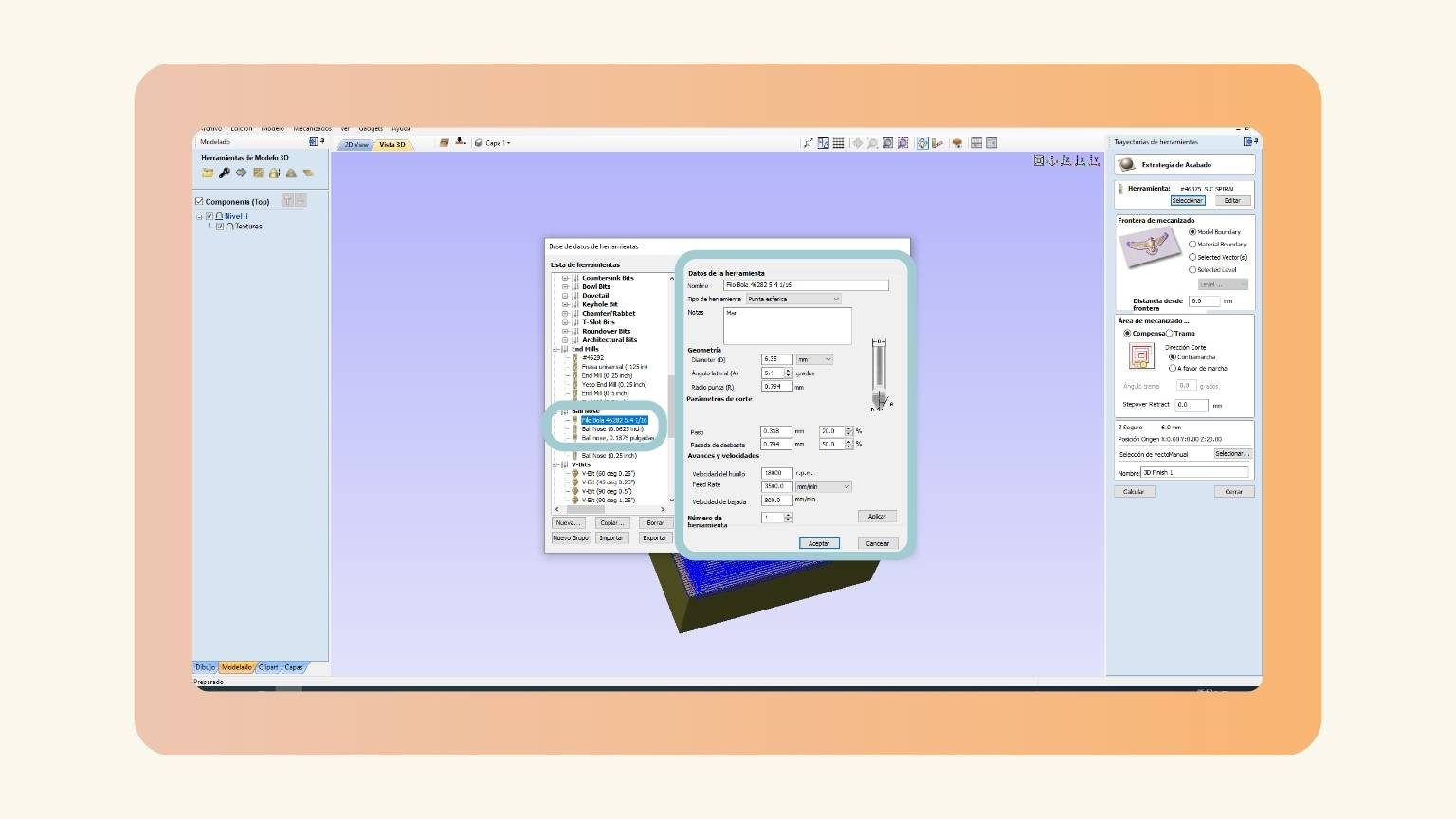
- I checked the tool, and it wasn’t the correct one.
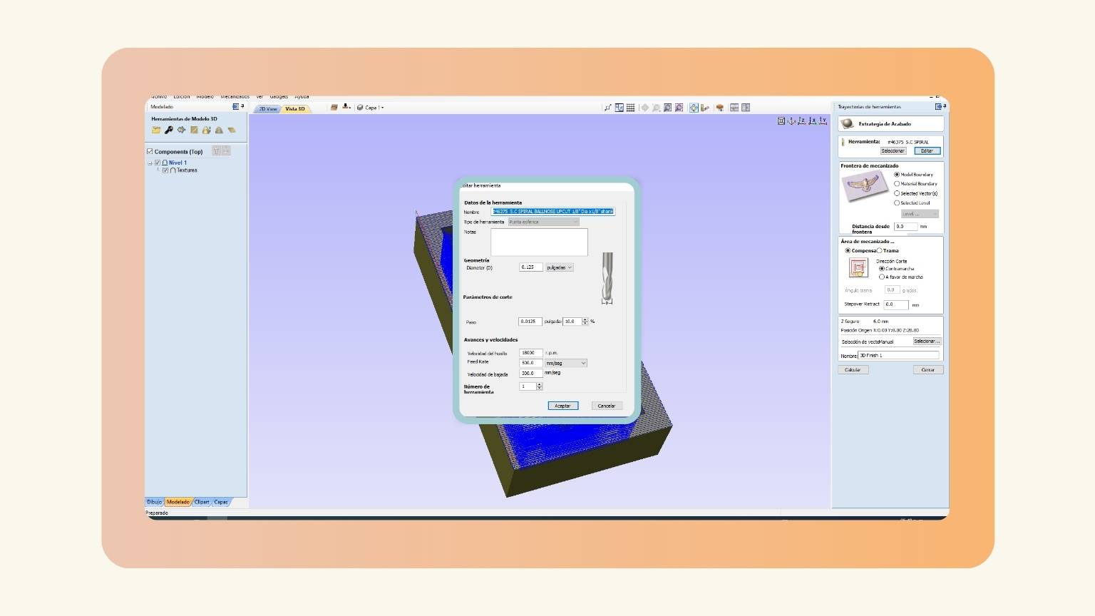
- I clicked on the ‘Selection’ option to select the correct tool.
- I found the tool in the ‘Ball Nose’ section, and I checked if the dates of the tool were correct.
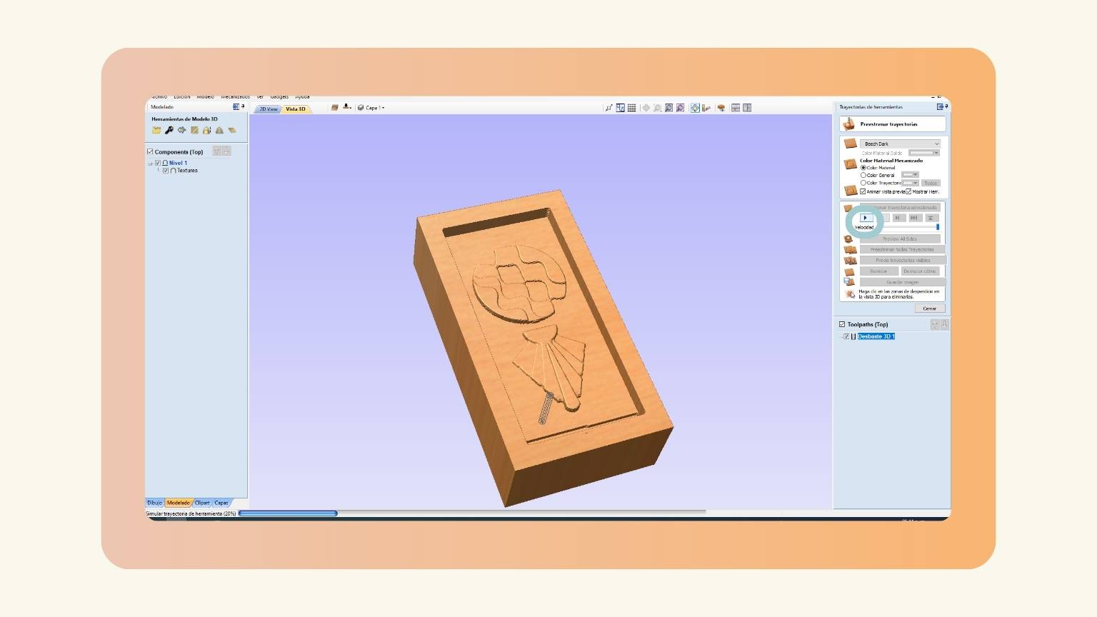
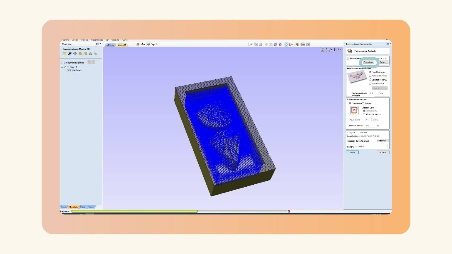
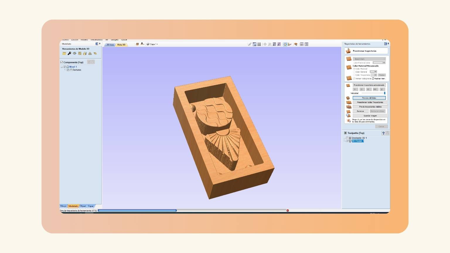
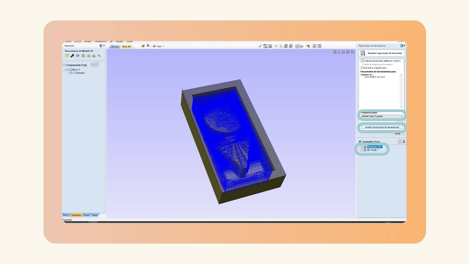
- I selected the ‘Pre-release tools’ to see the trajectories of the tools.
- This was the preview:
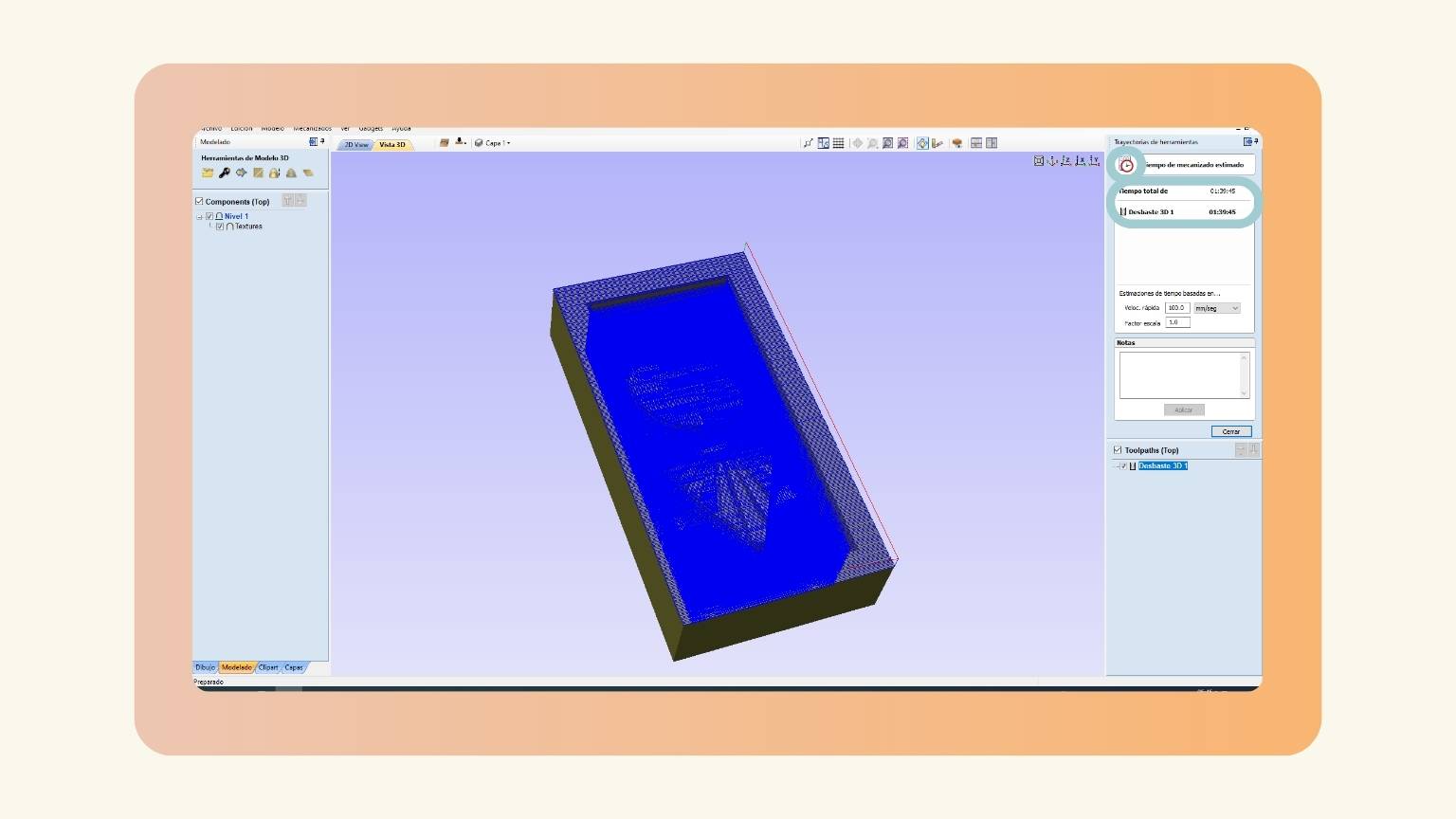
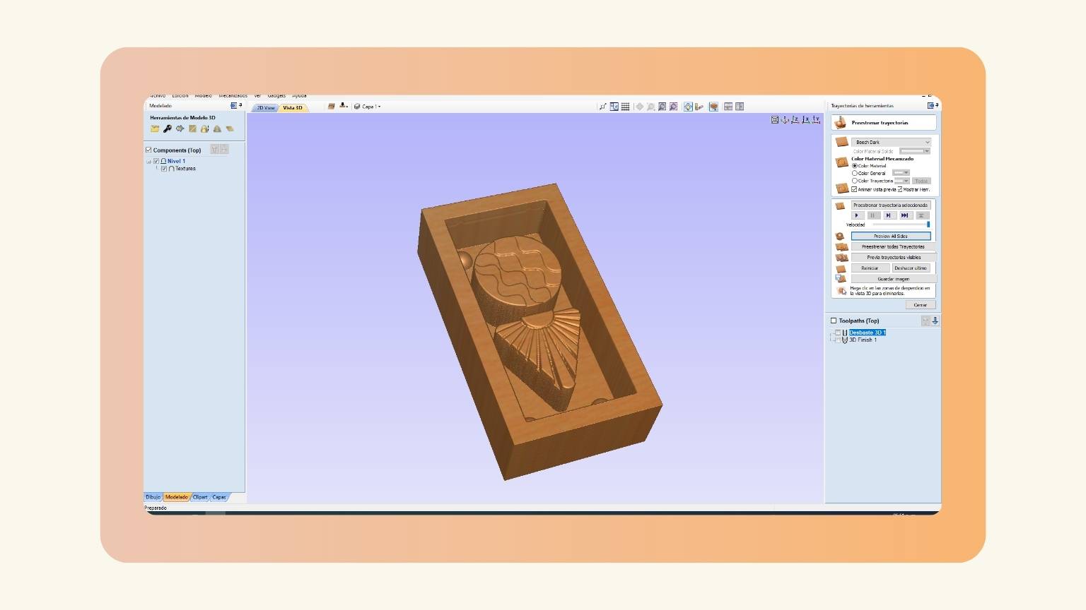
- After, I looked at the estimated machine time.
- Finally, I saved my files. For this, I pressed ‘Save tool paths’.
- I replaced the processor with an Asia Robotica.And I saved the file, first the roughing and next the finising.

Cut Time
Recap
The machine used for cut the model is...
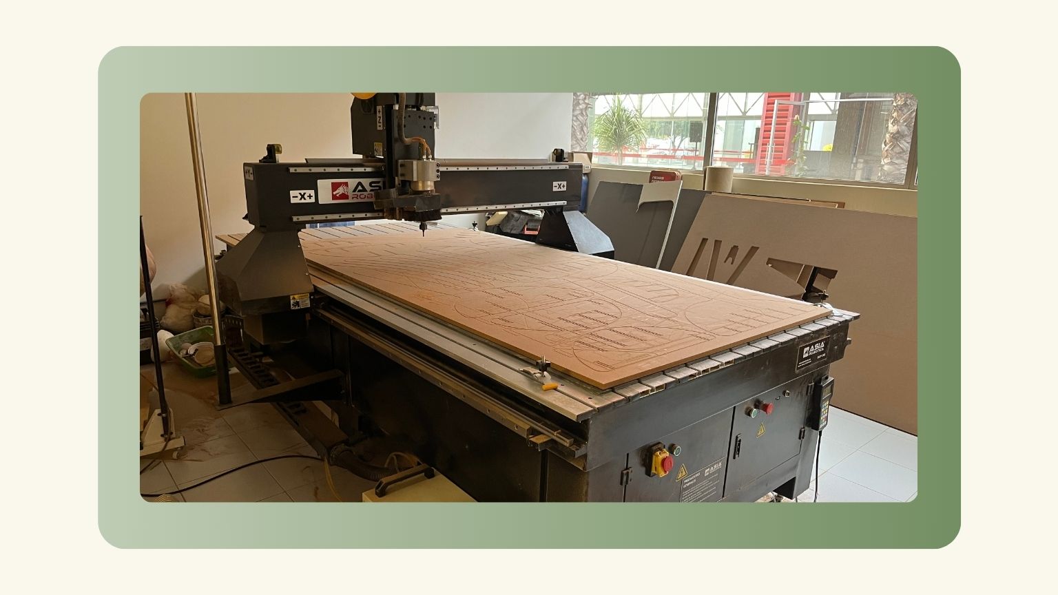
The Asia Robotica
A router CNC which has a 6 Hp water-cooled Spindle motor at 24,000 rpm, has 4 suction areas to adapt to your cutting needs, has an assembly design thought to forget about vibrating cuts and/or imperfection in the work and includes a cabinet integrated to the structure of the equipment, to minimize space.
Steps:
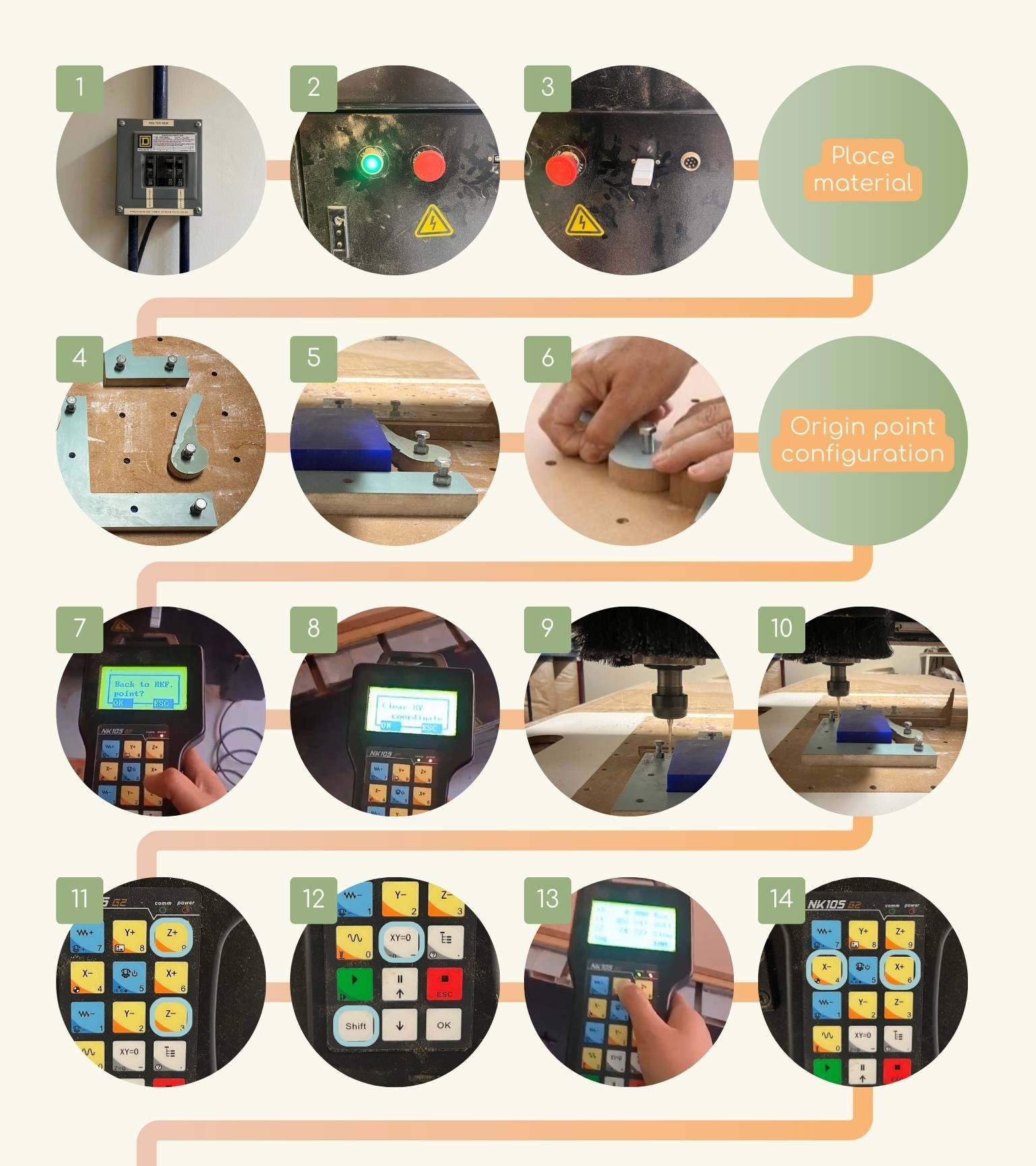
- Turn on the ASIA switches.
- Turn on the switch located at the front of the machine, specifically on the upper right side. It’s the green button.
- I plugged the USB into the input located on the right side of the emergency stop.
- Note: The "G" code file should already have been loaded on a USB flash drive to be inserted directly into the machine. Continue with the following steps:
- I fixed the table with clamps, and started to place a reference as a frame for the piece.
- I placed the cams as close as possible to the material, to adjust them I put pieces of material that will limit the distance between the cam and the material.
- Then I tightened the cams.
- When you turn on the machine, an announcement will appear on the machine control saying if you want to go to the reference point, and I press ‘OK’.
- I cleaned the XY coordinates to reconfigure them.
- First, I moved the z-axis upward.
- When it was high enough, I moved the ‘x’ and ‘y’ axes so that the position would be in the center of the workspace.
- Then, I set the position of ‘z’ using buttons 3 and 9.
- Once I had the position delimited, I saved the position as the point of origin by pressing Shift and the ‘XY=0’ button.
- After that I configured the ‘x’ and ‘y’ positions.
- To do this, you control the axis with the machine control.
- I used buttons 4 and 6 to control the ‘x’ position.
- Note: If you want a slower or faster movement, you must press Shift to regulate the speed of the movement.
- Next, I used buttons 2 and 8 to control the ‘y’ position.
- Once the x and y positions were known, I saved them as the point of origin with the ‘XY=0’ button.
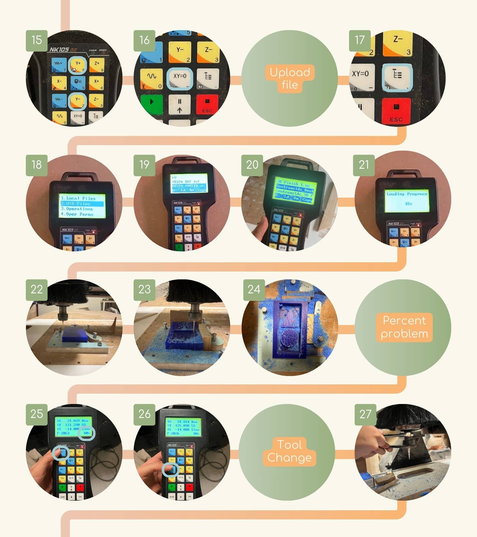
- I went back to the control menu, pressing the button with a diagram.
- I selected the ‘USB Files’ option to find my file.
- I searched for my file, and once I found it, I copied it to local memory.
- I went back to the main menu and now selected the ‘Local Files’ option.
- And browse for the file you copied; once I found it, I selected it with OK.
- Then, I moved the coordinates of ‘x’, ‘y’ ,and ‘z’ to the middle of the workplace.
- Finally, I started the cut.
- The cut ended.
- I noticed that my cutting was going slower than expected, so I checked and in the lower right corner it said that it was working at 30%, so I had to increase this percentage with button 7 on the control.
- And to decrease it, you must press the with button 1 of the control.
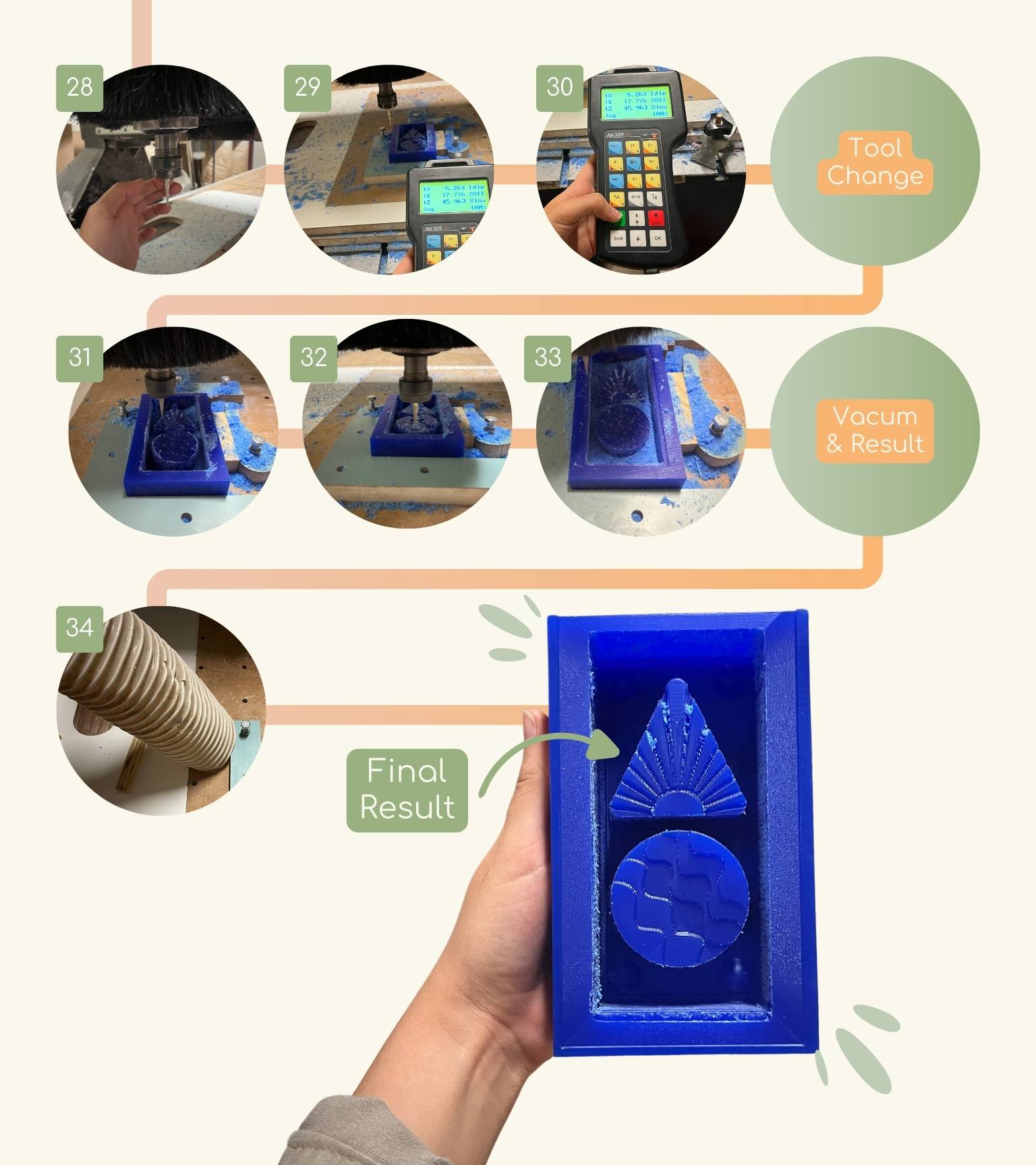
- To change the tool, I used two wrenches to loosen the nozzle of the tool.
- Then I put the new tool in place and with the wrenches I tightened.
- I vacuumed the residues generated by the cutting.
- And at the end of all the steps you can see the result.
Place material
Origin point configuration
Upload file
Percent problem
Tool Change: finishing
Vacum & Result
Making the Mold
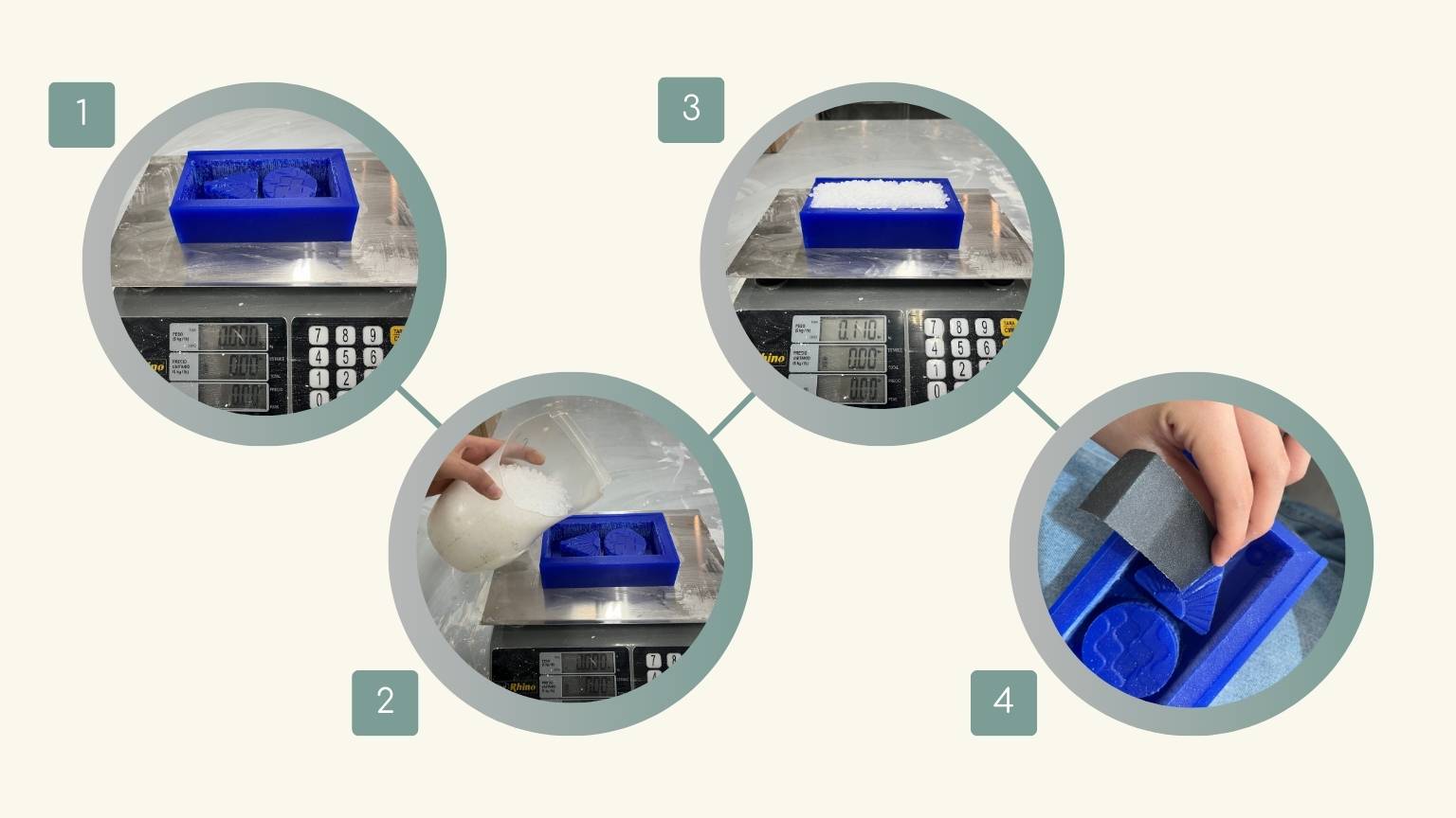
- I placed my mold on the scale, pressed the Tab button to disregard the weight of the mold.
- I used plastic pellets to measure the volume of my mold.
- I started to fill my mold with pellets and when I reached the edge I stopped to check the weight of the pellets.
- Since my piece wasn't perfect, I sanded some areas a little.
- Then, I decided to make a mixture of grenetina and water to see if my mold would work. Besides, this option was more convenient to know if my mold would work or not.
So,I prepared the mixture and poured it into my mold.
- Note: I used Vaseline as a release agent.
- The consistency was like this, I placed my mold in the refrigerator to have a better consistency.
- Afterwards, I ran a small spatula along the walls to make it easier to unmold.
- I unmolded my piece.
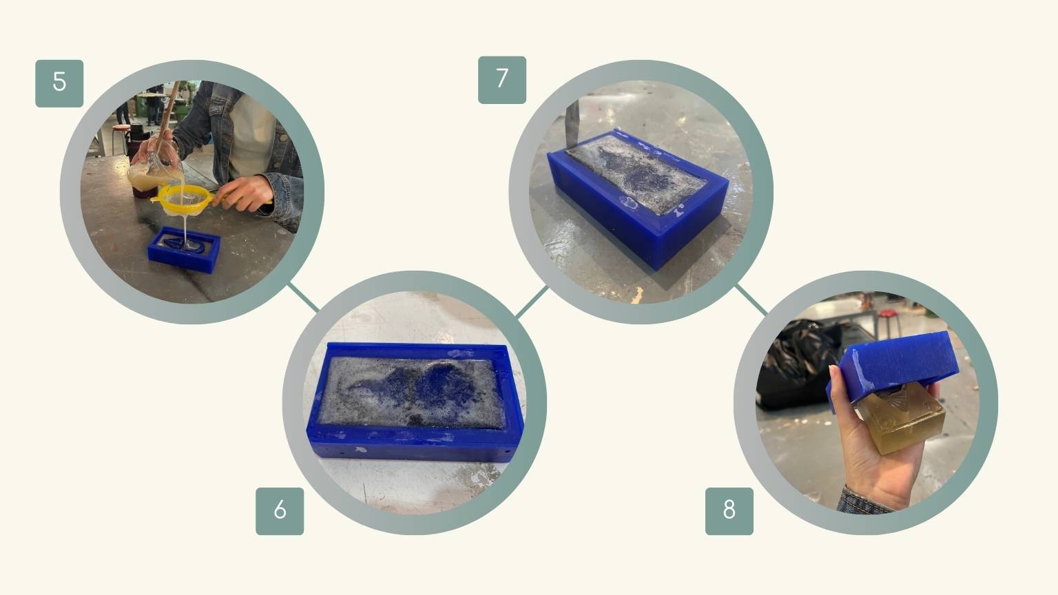
AND THIS WAS THE RESULT:
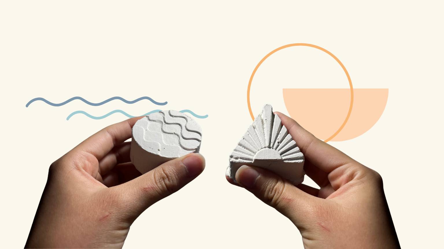
Making the Pieces
I decided to give it a try and see if I could get some plaster pieces out of my gelatin mold. To my surprise, it worked!!
Conclusion
While it was not the practice I would have preferred, I believe it was an excellent improvisation as we proceeded. I gained valuable insight into the various considerations involved in mold-making, including the importance of the material used in mold fabrication.
Moving forward, I will conduct tests with silicone and other materials for the final pieces, as my original plan was to experiment with bioplastics. Furthermore, I will machine the counter mold I designed to test it.