Final Project
Have you ever wondered what an emotion feels like? How do you hear it?
I'm really interested in exploring the complexity of emotions. I've been wondering lately if it's possible to accurately convey emotions through language. Describing the physical sensations associated with happiness, like the warmth of a hug or the sensation of the sun in your hands, is easy enough with a object. But what about emotions like tranquility or sadness? How can we accurately describe the feeling of calmness when near the sea or the sadness that comes with loss?
I want to create an experience of senses and feelings. Representing all aspects of a feeling with an object can be really tough due to its complexity. But you know what? Recognizing a feeling through sounds is totally possible and the shapes are also a way to feel the colors and feelings from symbolizations.
Think about the happiness… you can sound laughs, the song of birds…
Research
Inspiration
Constanz System
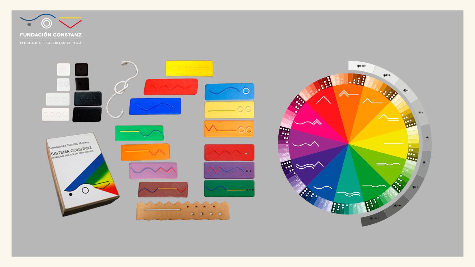
Source: Sistema Constanz (n.d.)
Didactic material is in the form of a language of touching color, which has its origin in the codification of primary colors. Its structure in codes comes from the relationship between the movement, form, and color of three natural elements: the waves of the sea, fire, and the sun's rays.
Ivy
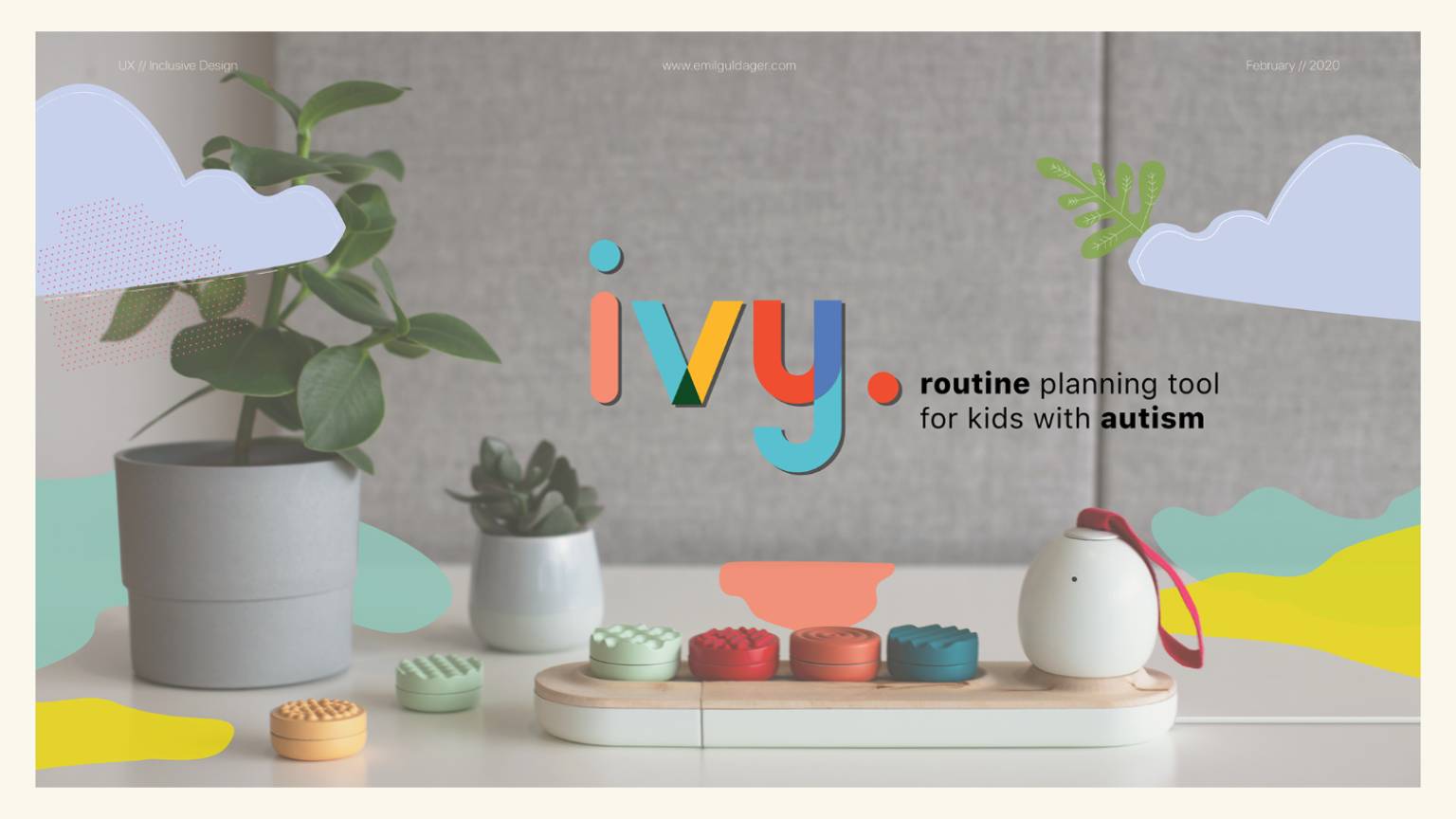
Source: ivy (2020)
A sensorial routine planning tool that allows kids on the autism spectrum to plan their day by creating a ‘melody of the day’. This melody is built from different textured and colored pebbles that each has a unique sound.
Feelipa code
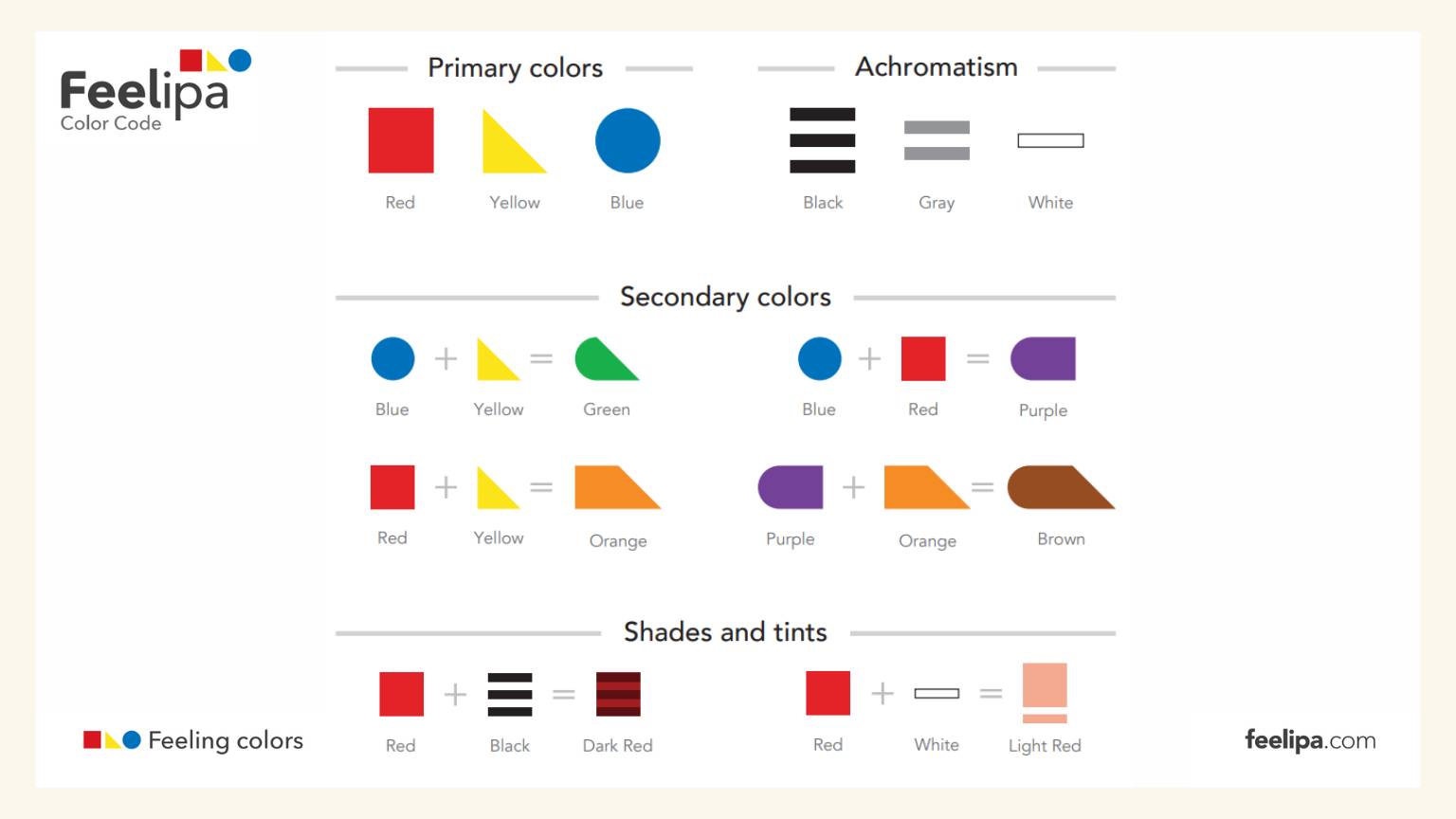
Source: Feelipa Code (n.d.)
A very simple, easy to memorize and universal color code, by being associated with globally recognized geometric shapes. By presenting itself in relief, it is easy for anyone to correctly identify colors.
Idea
My idea consists in create this:
- A base to put the three primary colors.
- A system that generates a specific sound of the shapes and feelings.
- Three shapes:
- Square-Represents the red and the angry.
- Circle-Represents the blue and the sadness.
- Triangle-Represents the yellow and the happiness.
- Others shapes:
- Three rectangles-Represents the black and the scare.
- Two rectangles-Represents the white and the calm.
-
(I'm still evaluating its permanence.)
- An application that allows users to create sounds that represent particular emotions and save them in the appropriate formats.

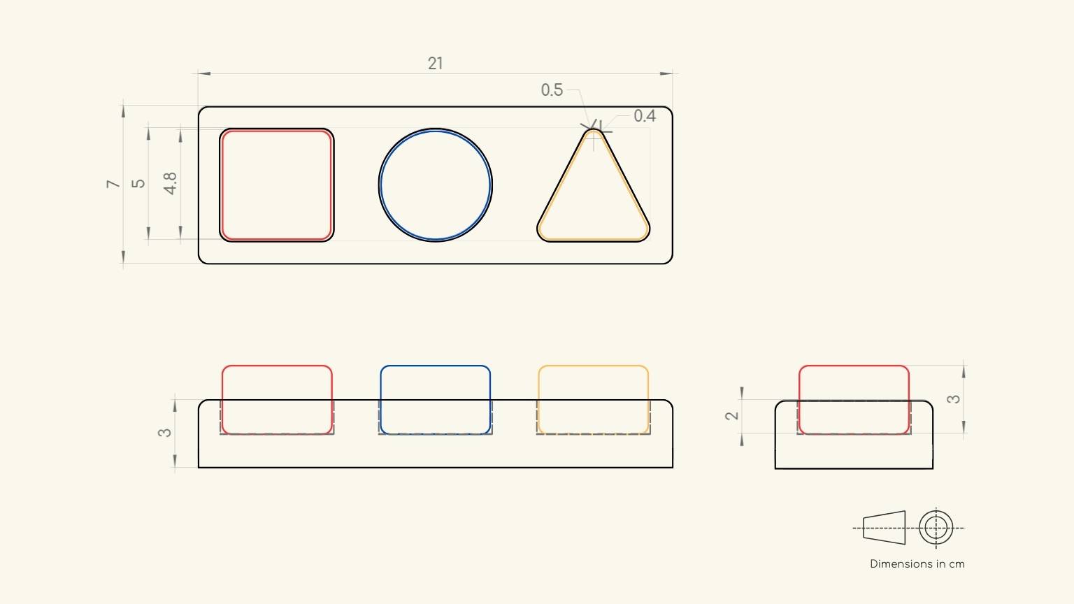
I discarded the notion of merging the black and white forms and based on that, I broke down some of the fundamental measures for product development; however, additional factors must be integrated to ensure that the measurements are proper. However, this is an excellent start for test development.
Another’s functions (that could be considered):
- The color should be generated with light when the shape is placed on the base.
- Include some texture in the shapes.
- Include guides on mindfulness.
- The application enables users to create sounds that represent particular emotions and save them in corresponding formats
Objetive
Create a unique emotional experience by exploring your feelings in a distinctive way. You have the freedom to express your emotions and compare them to the sounds of your daily routine. Furthermore, you have the opportunity to experience and symbolize a wide range of human emotions.
After multiple interactions....
My project comprises didactic and playful material designed to facilitate the acquisition of knowledge about the basic colors and the combinations that can be formed between them. Each color will be represented by a geometric figure. In order to facilitate the identification of colors through touch, these figures will be created from silicone molds. To facilitate the identification of colors, a base will be constructed where each figure can be placed. When the figures are placed, the base of the corresponding color will be illuminated. This will be accomplished through the use of a tactile sensor.
Before elucidating the manner in which I discerned the viability of my project, it is imperative that I divulge certain crucial details pertaining to the construction of the prototype.
What will you design?

- Textures. To offer children a sensory experience, I will create three different textures for each geometric form, with a relationship based on the associated color.
- Sensor. I'll create the tactile sensor since I want it to have a transparent base that reflects the light from the Neopixels onto each figure. That is why I will design my own sensors.
- PCBs. I'll create one PCB per figure to better distribute light based on the geometric form.
What materials and components will be used?
Components:
- 3 ATTiny 45.
- 44 Capacitors.
- 4 LEDs.
- 6 Resistances .
- 1 ESP32-C3
- 14 Neopixels.
- Cables Dupont.
- Acrilic
- MDF
- Epoxic Resine
Where will come from?
From local stores (QuimicPlasctic, Impresoras SD Puebla, Home Depot) or online (Amazon, Adafruit, SparkFun, DigiKey).
Note: Some materials could be obtained from material discarded by students inside the university.
How much will they cost?
| Amout | Component | Price |
|---|---|---|
| 3 | ATTiny 45 | 5.97 |
| 4 | LEDs | 0.60 |
| 10 | Resistors | 0.18 |
| 14 | Neopixels | 8.40 |
| 1 | Seeed Studio XIAO ESP32C3. | 9.90 |
| 57 | Pines | 12.60 |
| 1 | Resine | 43.82 |
| 1 | Acrilic | 5.90 |
| 2 | Copper Sheet | 2.16 |
| 1 | Wax | 20.82 |
| 1 | Silicon | 35.84 |
| 1 | MDF | 7.84 |
| 154.04 | ||
What parts and systems will be made?
- PCBs.
- Shapes.
- Case.
- Supports of PCBs.
- Interface.
What questions need to be answered?

- How will I program the color combinations?
- Which library will I use for the touch sensor?
- How will I guarantee the contact of the figures with the base?
- What elements will I use to generate the contact of the figures with the base?
- How will I communicate with each of the PCBs?
- What safety measures should I follow to guarantee its use with children?
How will it be evaluated?

- Accuracy test of the sensor.
- Test of communication between boards.
- Interface test.
- Usability tests with users.
System diagram & Processes
In order to gain a comprehensive understanding of the elements that comprise my final project and the progress made in its development, I proceeded to analyze each of them in detail. This was reflected in a diagram of the system.
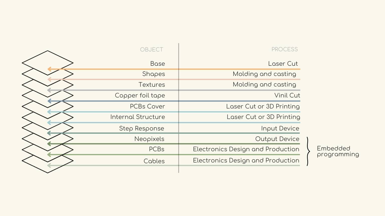
The following section will provide a concise overview of the methodology used in project construction.
Base & Structure
Process: Laser Cut
Part: Internal Structure
The structure of my project was constructed using laser cutting, as this method allows for the creation of a robust and stable framework upon which the various components can be integrated to form a unified system. Stereotomy was employed to adapt the structure to accommodate the specific requirements of each component. Three-dimensional printing was not employed due to the time constraints associated with the desired dimensions. However, the precise measurements could be used to fabricate certain components, if not the entire structure.
So, I made these pieces:
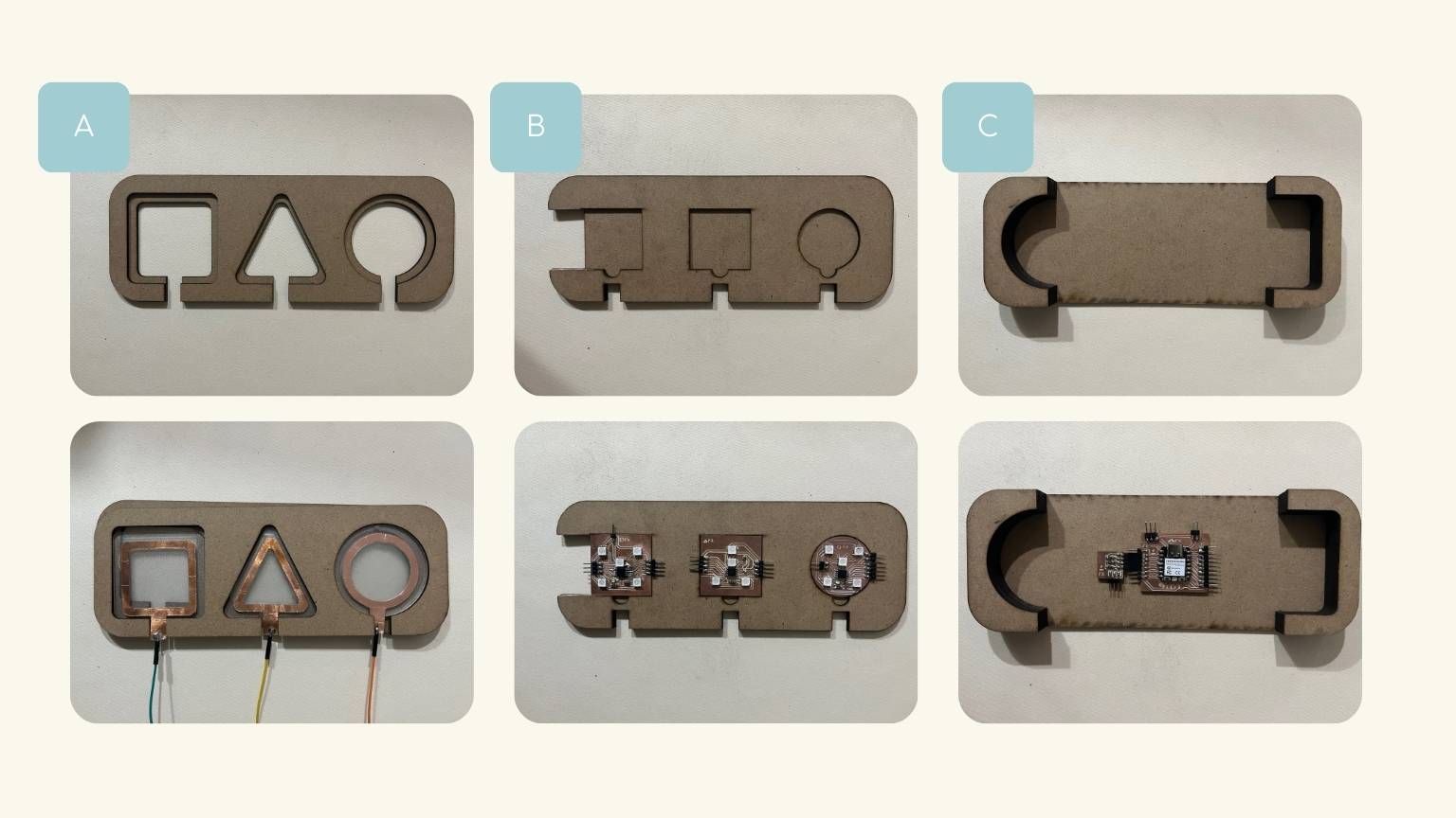
- Base for the acrylic.
- Base for the PCBs.
- Final Base - Master PCB and Step Response PCB (Module)
Part: Base / Cover
Conversely, in order to achieve the desired rounded corners of my rectangular body, I employed a patterning technique that would permit the creation of a more fluid shape. Furthermore, this resulted in a more visually appealing product.
In order to achieve the desired outcome, a series of tests were conducted, the majority of which involved measuring the pattern's flexibility and level of rigidity. And this was the final result:
The result:

File: dxf
Shapes
Process: Molding & Casting
I used the mold I made during the molding and casting week, but this time I made my mold out of silicone so I could use epoxy resin. In this case, I wanted the figures to have some transparency so that the light could shine through them, but to add a touch of color, I decided to add diamantine of the appropriate color to the figure.
So how did I make my shapes?
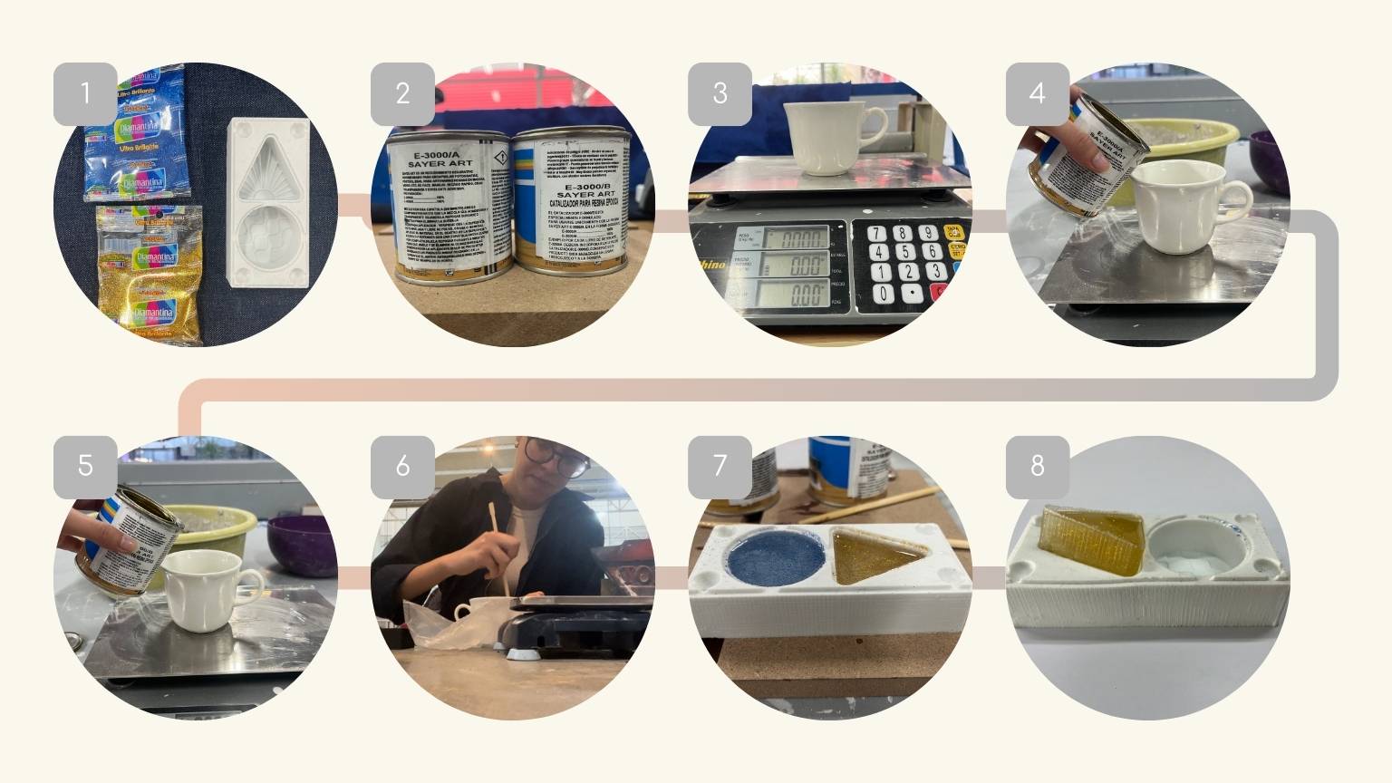
- I got my silicone mold.
- I bought the resin and catalyst.
- I used a container to weigh the amounts of resin and catalyst (it was a 50/50 ratio).
- I started pouring the resin.
- I added the catalyst.
- I stirred.
- I poured it into the mold and added the diamatine.
- After a day of curing, I removed the mold.
The result:
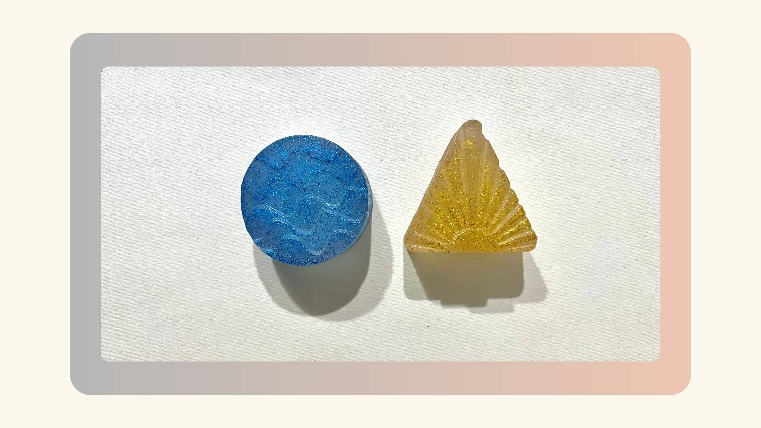
File: stl
Input device
To create the touch sensor that my project required, I looked through Nadieh Bremer's documentation, especially his Input Device Week. So, as I read the ones I had created, I weighed two options:
- Use copper tape.
- Alternatively, use copper rivets.
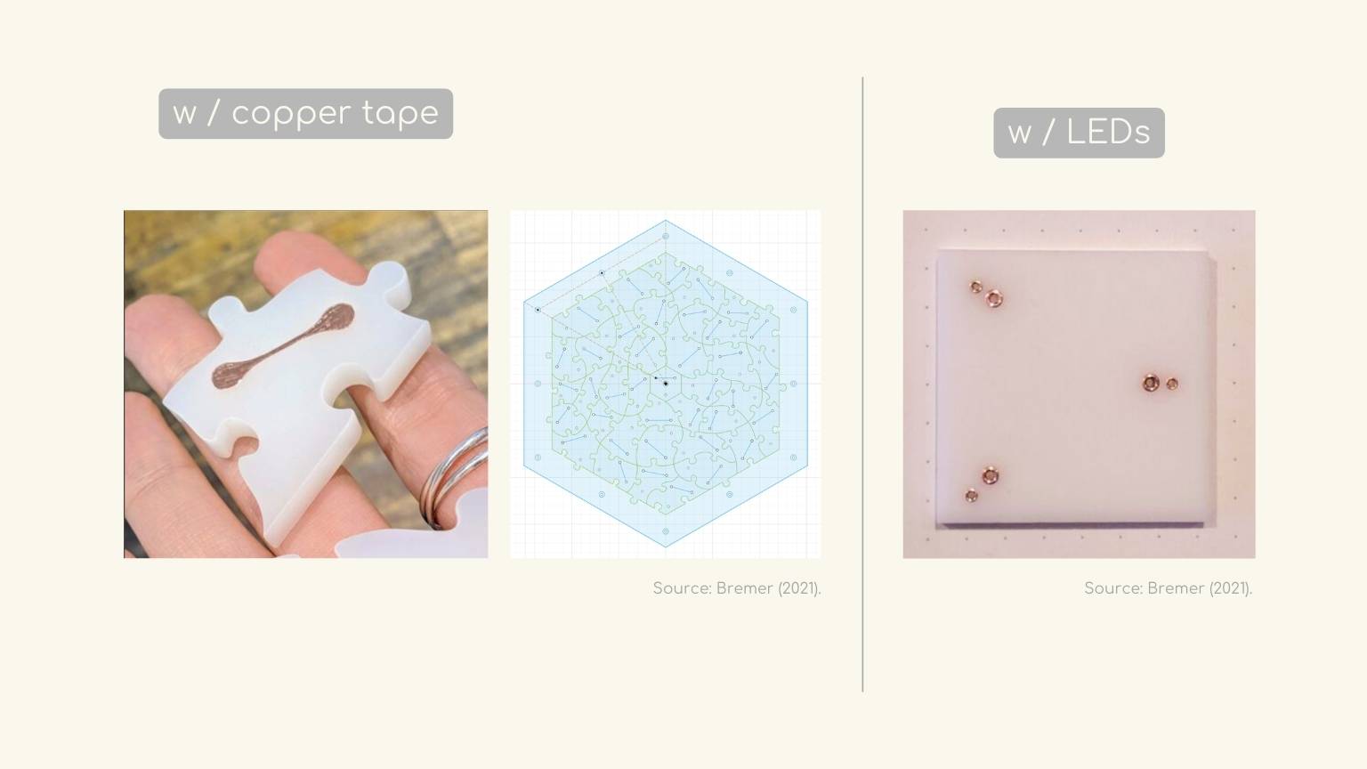
In my situation, I chose copper tape considering that I did not need high precision in the spot where I would insert the tape, as it had to be in the contour to keep the ' light output for the emission in the figures.
Therefore, I performed the following operations:
Process: Vinil Cut
Part: Copper foil tape
I used the Vynil cutter to cut the copper tape. In particular, this cutter used the program Silhouette Studio, so the file was prepared to perform the necessary tests. These tests were performed because the program could scale the file, so the process was as follows:
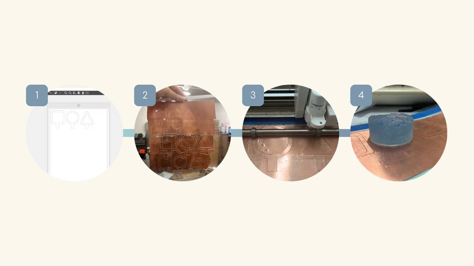
- I opened the file in Silhouette Studio.
- I cut the final file.
- I checked that the size was correct.
Note: I proceeded to cut the ribbon, which was to be affixed to each figure, as well as the acrylic
The result:
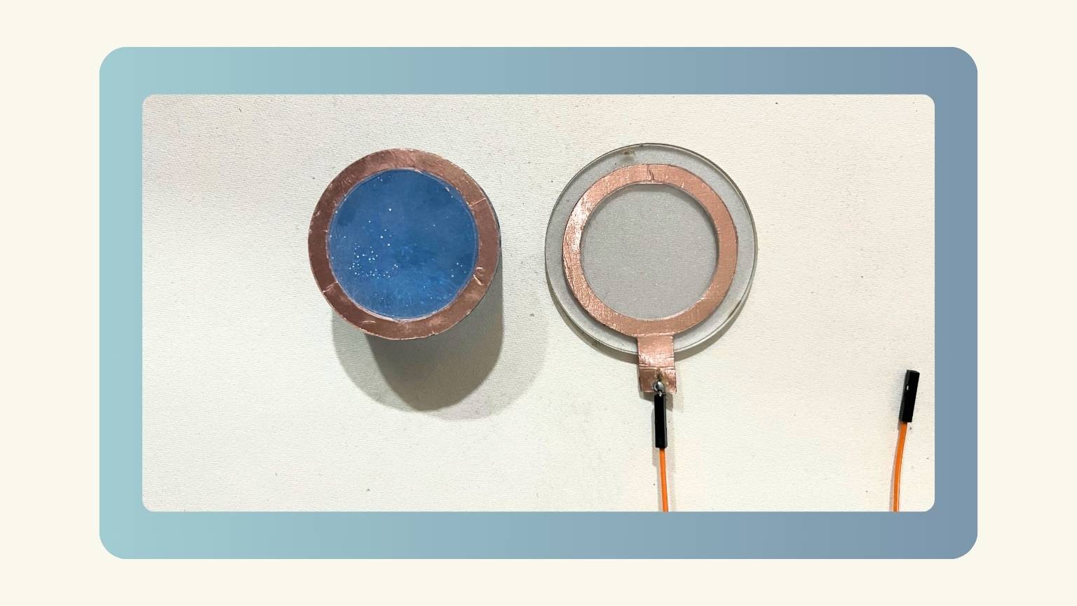
File: dxf
Process: Laser Cut
Part: Acrilic Base
In order for the light to be emitted, an acrylic base was constructed to serve as a platform for the figures. However, the acrylic I had at hand was transparent, and to prevent the light from being too intense, I applied opaque frosted vinyl to it before cutting it. The subsequent process was as follows:
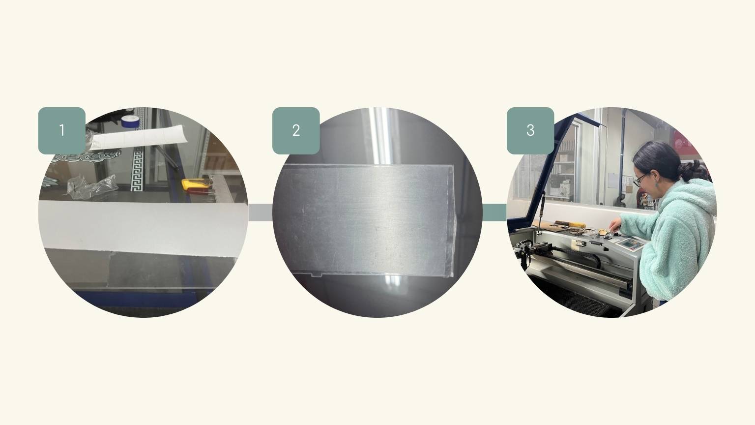
- The frosted vinyl was then cut to the requisite dimensions.
- The vinyl was then applied to one side of the acrylic.
- The acrylic was then cut using a laser cutter.
The result:
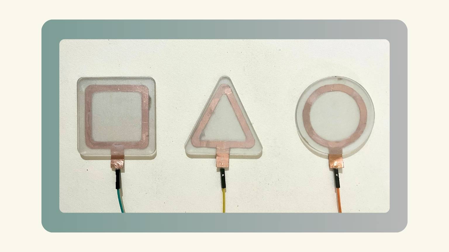
File: dxf
Process: Electronics Design and Production
Part: PCB Toach Sensor
Ultimately, I constructed the plate in accordance with the specifications of the touch sensor. Admittedly, this proved to be a somewhat intricate undertaking, given the abundance of disparate documentation on the subject. Consequently, I elected to rely on the most pervasive and comprehensive of these sources, thereby ensuring a more robust foundation for my own understanding.
The schematic of the board I constructed is as follows:
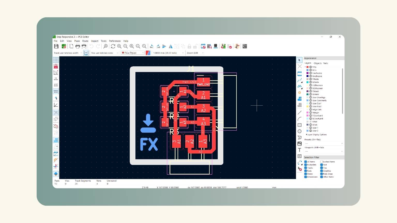
- The board was constructed as a module that would be connected to the main board.
- The circuit incorporates three resistors, with each resistor corresponding to a sensor that will be connected to a respective figure.
- An additional resistor is included in the circuitry, which connects to the three resistors. This resistor can be connected to either ground or another pin, which will fulfill the function of a tactile sensor. The specific pin to which this resistor is connected depends on the programming library.
The result:
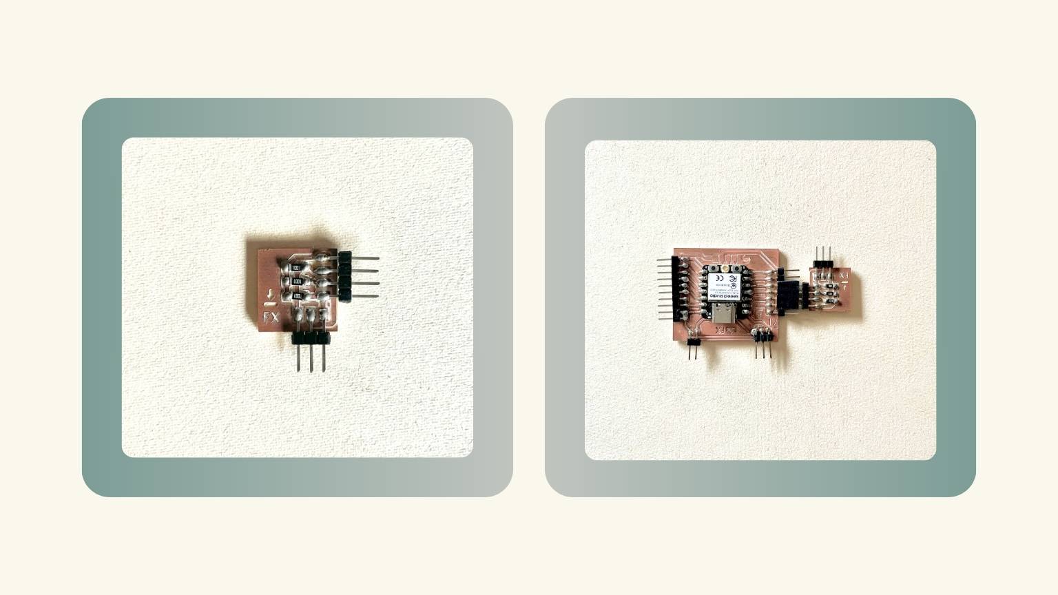
File: KiCad
Output device
While evaluating the outputs, I considered using LEDs as the medium for detecting the touch sensor. However, I determined that this approach was not feasible due to the high pin consumption of each LED and the need for a large number of them to achieve the desired light level. Therefore, I opted for Neopixels, which allowed me to create three boards (one for each figure) with three different LEDs for each figure.
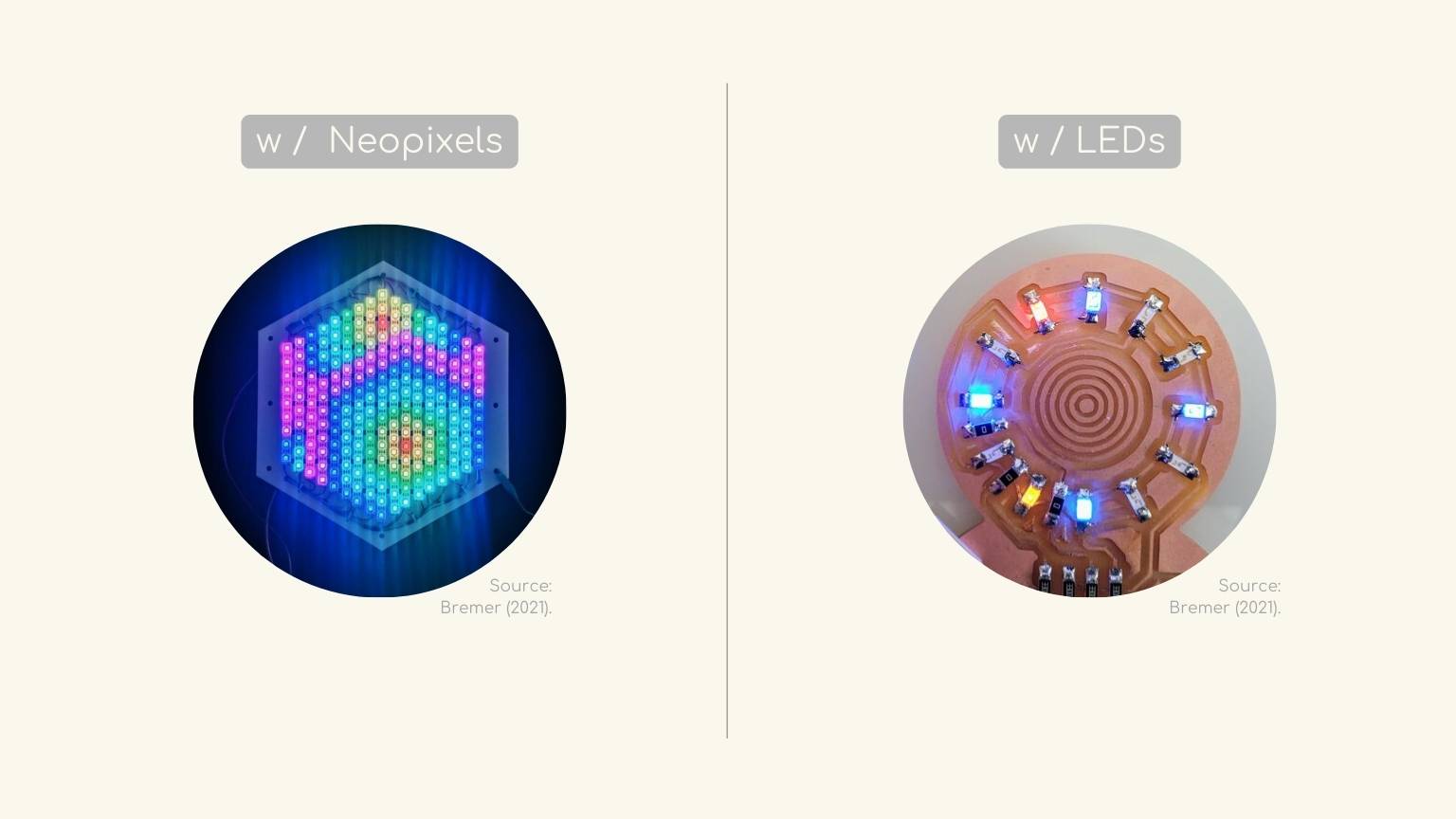
Part: PCBs Neopixels
Process: Electronics Design
The initial step was to create the design for each of the plates. My primary objective was to optimize the distribution of Neopixels to ensure uniform light transmission and sufficient illumination for the intended purpose.
So, these were the designs:
The result:
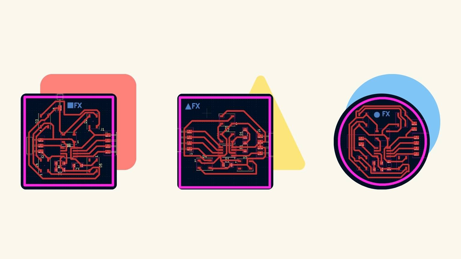
Files: KiCad
Process: Electronics Production
To create the boards, I completed the necessary steps, which are outlined below:

- The first step is to set up the corresponding file in Moods.
- I utilized the Roland SRM-20.
- I proceeded to place the copper plate that I would be cutting and the engraving tool.
- The engraving of the plate strokes commenced.
- Subsequently, I switched to a different tool and proceeded with the contour cutting of the plate.
The result:
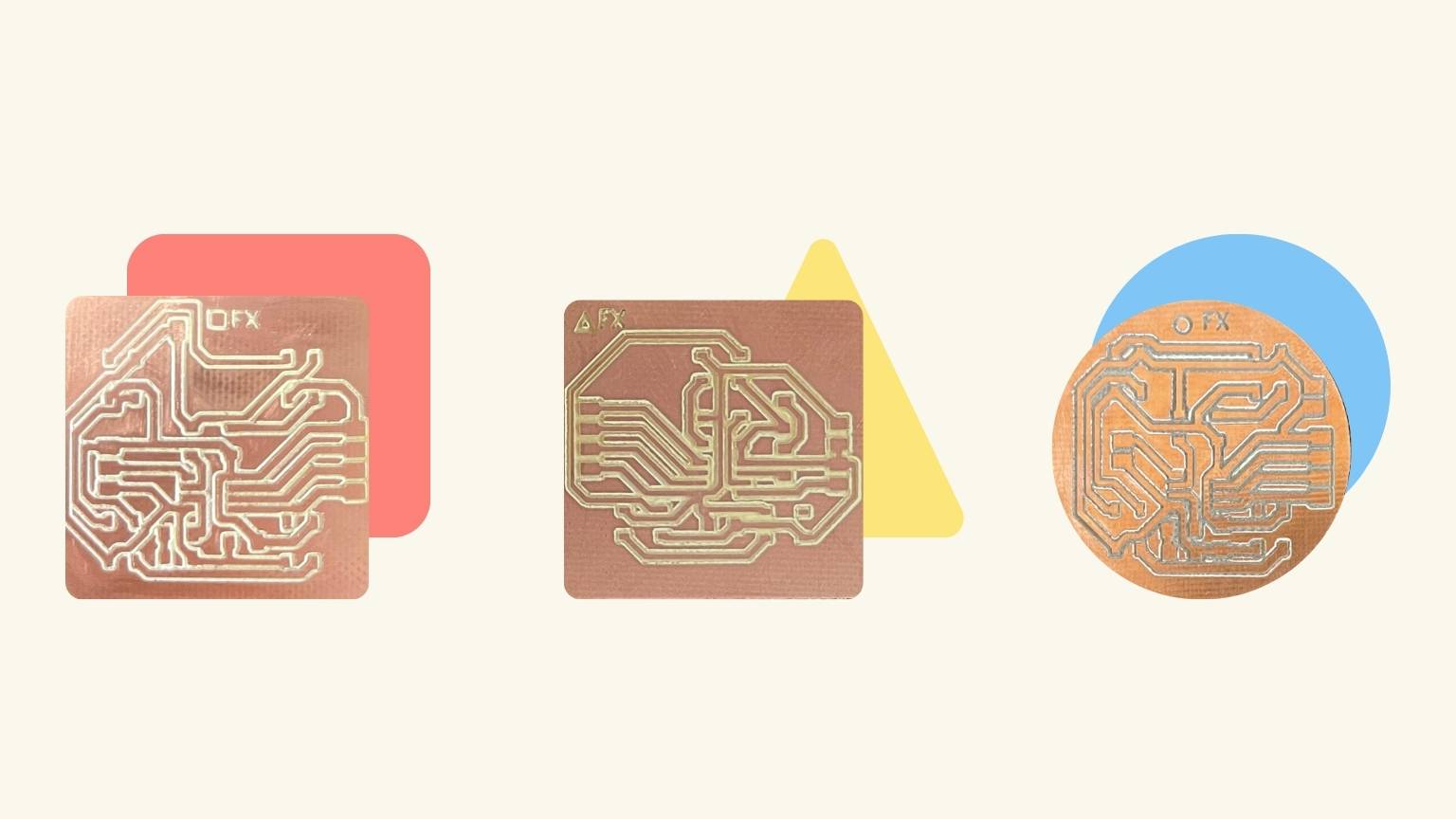
Process: Soldering

- Once the boards were cut, the components required for their operation were soldered.
- Each of the boards was soldered with the necessary components, which included an:
- 1 Attiny 45
- 4 Neopixels
- 1 LED
- 1 resistors
- 1 capacitor
- 8pins
- Note: the board corresponding to the triangle only has 4 Neopixels.
- After soldering them, the corresponding tests were made to check their functionality.
The result:
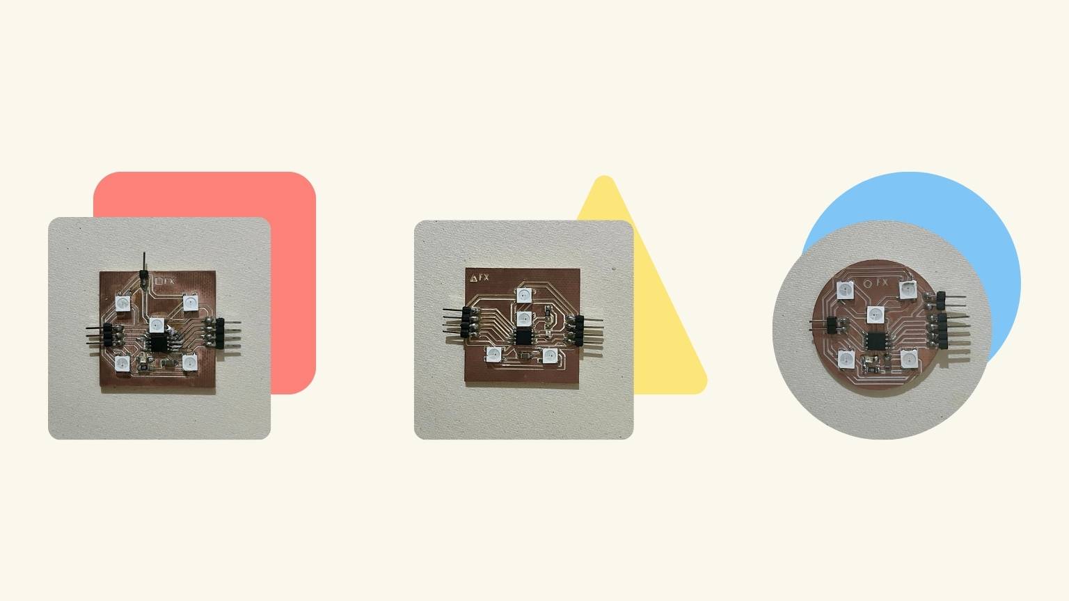
Process: Embedded Programming
Finally, to enable the touch sensor to detect the placement of the figure and to activate the Neopixels in response to the received signal, I conducted a series of tests to ensure the desired outcome.
- The initial test was conducted using an Arduino, a breadboard, a resistor, and an LED.
- Subsequently, I designed the circuit board to function as a sensor and conducted a test to verify its functionality.
- Then, I tested it with a different library and a different connection setup.
… and everything works
In order to facilitate the process, I created the corresponding codes for each of the PCBs that I would be using.
Firstly, the master:
In the setup section, the code includes libraries and defines constants for the I2C addresses of three ATtiny85 slave devices, touch pins, LED pins, and threshold values.
- Serial connectivity is initiated for debugging, and the LED pin modes are configured.
The loop constantly reads information from three touch sensors (touchValue1, touchValue2, and touchValue3).
- These sensor data are then shown on the serial monitor for monitoring purposes.
- The sendCommandToSlave method sends commands to three slave devices, depending on sensor data.
The sendCommandToSlave function accepts the slave address and touch sensor value as arguments.
- It starts I2C communication, writes a command (1 or 0) based on the touch value, and then terminates the transmission.
Secondly, the slaves:
In the setup section, the code sets the ATtiny45 as an I2C slave using the supplied address (SLAVE_ADDRESS).
- It initializes the Neopixel strip and registers the receiveEvent method to handle incoming I2C input.
The loop monitors I2C activity and conducts actions based on the command variable.
- If the received command is 1, the Neopixel color is set to red via the setNeopixelColor method.
- If the command is 0, it disables all Neopixels by first emptying the strip (strip.clear()) and then updating it (strip.show()).
To receive an event, use the function receiveEvent(uint8_t howMany). This method is invoked automatically when data is received over I2C.It reads data from the I2C bus and stores it in the command variable.
To set the Neopixel color, use the setNeopixelColor (uint32_t color) function. This function determines the color of the Neopixel strip..
- It iterates through each Neopixel in the strip, changing its color to the provided RGB value.
- After adjusting the colors, it invokes a strip. show() to update the Neopixel strip and reflect the color changes.
Note: The SLAVE_ADDRESS, neopixelPin, numPixels and strip.Color will change according to the slave being programmed.
The result:

Files: Codes , Master PCB & Connection PCB
Presentation
Slide

Video
the end? ...or just the beginning of something
