2. Computer Aided Design
Have you heard of Computer-Aided Design (CAD)? It's a technical tool used by engineers and designers to create technical drawings and models.
3D model
For this week's assignment, I created three-dimensional objects in Solid Works and Rhino, which are both really useful tools for bringing ideas to life!
But what exactly are Solid Works, Rhino and Fusion 360?
Solid Works
Solid Works is a computer-aided design (CAD) software for mechanical modeling in 2D and 3D, in other works in two-dimensional and three-dimensional space.
Some of its features are:
- Intuitive user interface.
- Parametric modeling.
- Run simulations that allow designers to accurately test the performance and behavior of their models under a variety of conditions.
- Applications across industries.
- See all your steps in the menu to the left.
- Note: I used the desktop of my computer.
- If you come across an error or a function is unavailable, it'll give you a table for the function that was in error.
Rhino
Another software that I use is Rhino. It's a great tool that lets you create, edit, analyze, document, render, animate, and translate NURBS curves, surfaces, and solids; subdivision geometry; and point and polygon meshes.
Relevant features:
- You do everything with precision.
- If you made a mistake, you would fix it.
- Note: If there is an error in your design, Rhino will tell you.
- Is accessible.
- You have a lot of tools at your disposal: points, curves, curves from other objects, surfaces, solids, and malls.
- You can create your own technical illustrations and 2D sketches of your three-dimensional object.
- They give you good quality in your models because they include tools to guarantee it.
P l u s :
- The renders are of higher quality than the other software I know.
- Its accuracy and flexibility make it possible to explore and build their ideas without having to spend much time learning “CAD”.
Fusion 360
Fusion 360 is an integrated cloud software platform that brings together CAD, CAM, CAE, and PCB. It provides all the tools you need to move seamlessly from design to manufacturing.
Among its features are:
- Use simple 3D modeling tools to experiment with different design iterations.
- Produce high-quality CNC-machined items using integrated CAD/CAM. Gain access to a unified electronic design.
- Discover manufacturing-ready outcomes via generative design.
- Collaborate and manage your files smoothly in the cloud.
Comparisson
| SolidWorks | Rhino | Fusion 360 | |
|---|---|---|---|
| Requirements |
|
|
|
| Features | VSketch ideas, experiment with features and dimensions, and produce models and detailed drawings. | Create, edit, analyze, document, render, animate, and translate NURBS curves, surfaces and solids, subdivision geometry (SubD), point clouds, and polygon meshes. | 3D design and modeling, Manufacturing, Electronics, Data managements, Additive manufacturing and Generative Design. |
| License | Commercial / Educational | Commercial / Students or Professors / Educational | Educational / Commercial / For personal, hobby use (free) / For startup use (free) |
| Cost | Term licenses start off at $2,820 per year, which includes subscription services and full technical support. Perpetual licenses start off at $4,195 per license plus the cost of two years of subscription services. | 995 US$ (Single-user). It is permanent and does not expire. Price includes technical support and upgrades |
|
| Applications | Desing and engineering, to develop a robust and fully functioned mechatronics system from beginning to end. | Architecture, prototyping, engineering, jewelry and industrial, graphic, naval and automotive design. | Electronics, Mechanical design, Furniture making, Architecture, Aerospace design, etc. |
What did I do?
Exploring SolidWorks
To start with the assignment, I decided to use SolidWorks.
Why SolidWorks?
I chose to use SolidWorks because it has many advantages that I have not yet fully utilized. It's a great time to learn about certain tools that will be useful in the future. SolidWorks provides a user-friendly interface that guides you step-by-step through the applications of the tools. It's both easy to use and understand.
How did I use it?
So, I tried to recreate in 3D a project that I did last year. It was all about designing a train for a rail project. The train had different wagons that were used for storage, and each wagon had a different function. Here's what I did:
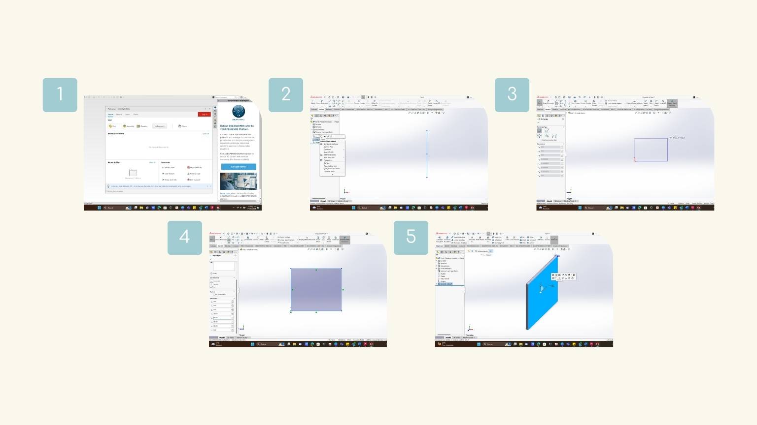
- Start creating a new document; to do this, click on ‘Part’.
- I choose the perspective that I use to make my first element.
- And I clicked to select the option that allows me to create a sketch.
- In the sketch, I did a rectangle.
- When I did it, I didn’t put in the measurements.
- I put the measurements; you can use the section on parameters in the right menu or the tool ‘Smart Dimension’.
- This latest tool works to modify the measurements of the created figure.
- Then, I extruded 12 mm of the figure.
- After, I created a new sketch of the lateral face.
- I made a line of reference to the other strokes.
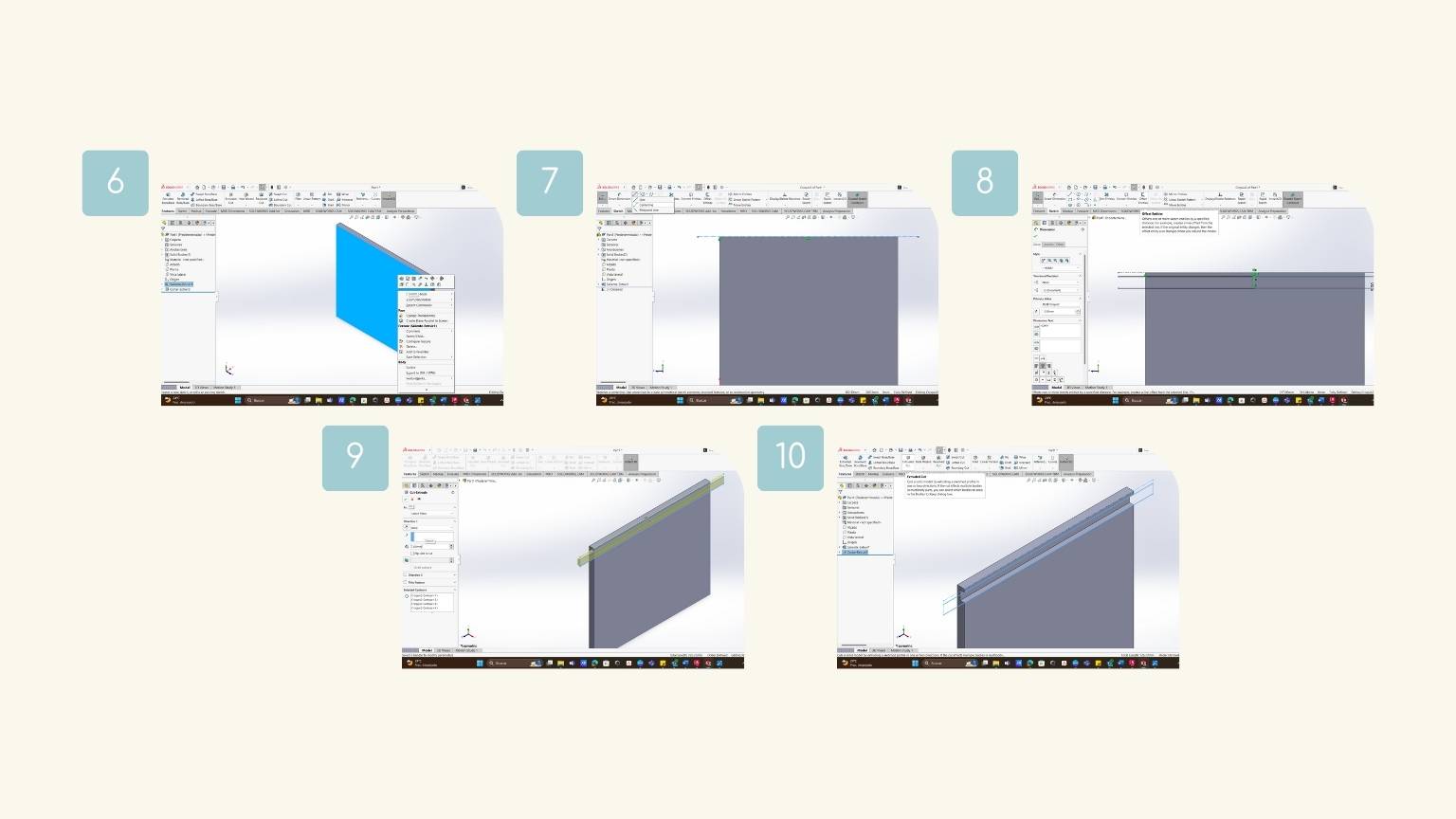
- I used the tool ‘Offset Entities’ to offer the reference line to do the next figure (a rectangle) that I would extrude.
- I extruded the rectangle towards the face of the figure already made.
- I used the tool ‘Cut-Extrude’ , it cut a solid model by extruding a sketched profile in one or two directions.
- And I have a rectangle with a devastated section.
- I started a sketch of the face on the face I was going to work on.
- I draw different reference lines to know where to start drawing the figures.
- I started by tracing the square.
- I filled the corners with a radius of 10 mm (but later I chanced to 7 mm).
- Note: To fillet, I used the tool 'Sketch Fillet' ; it rounds the corner where two sketch entities intersect to create a tangent arc.
- Then, I draw two circles 30 mm in diameter.
- Then I used the tool ‘Mirror Entities’, which consists of reflecting the entities as a mirror using a centerline or plane as a reference.
- I used the tool ‘Trim Entities’ to cut the interior lines in the figure and leave only the outline.
- This tool trims or extends a sketch entity to coincide with another or delate a sketch entity.
- From a square and centerlines, draw a trapezoid.
- I used the tool of line ‘Midpoint Line’, which consists of drawing a line from an intermediate point and extending to the sides.
- I drew two circles 25 mm diameter. Then, I used the construction of a square as a reference to do an arc using the tool ‘3 Points Arc’ to give the heart a more organic shape.
- The tool ‘3 Points Arc’ allows you to create an arc from the start pint, the end pint, and the height of the curvature you want.
- I used the tool ‘Polygon’ to create a hexagon, but I needed to make a reference circle so that the measurements would be proportional.
- And I filled the corners with a radius of 7 mm.
- I used the tool ’Ellipse’ to create an oval with two measures: 50 mm of height and 40 mm of width.
- And finally, we have our six traced figures.
- I select the sketch where I draw the figure and select the feature ‘Cut-Extrude’i> to make the corresponding holes in the part.
- Tip: I put a measurement that goes beyond the thickness of the piece to ensure the cut.
- The cuts are ready!
- I created a new sketch on the lateral side. And I did a series of rectangles on the outline.
- In the laterals, I draw rectangles with 12 mm of weight and 32 mm of height.
- In the base, I draw rectangles up to 47 mm in weight and 12 mm in height.
- Note: One rectangle is a geometric construction of reference, and the nest was a draw to extrude.
- I used the tool ‘Cut-Extrude’ to cut the rectangles to the full thickness of the piece.
- This piece is ready!
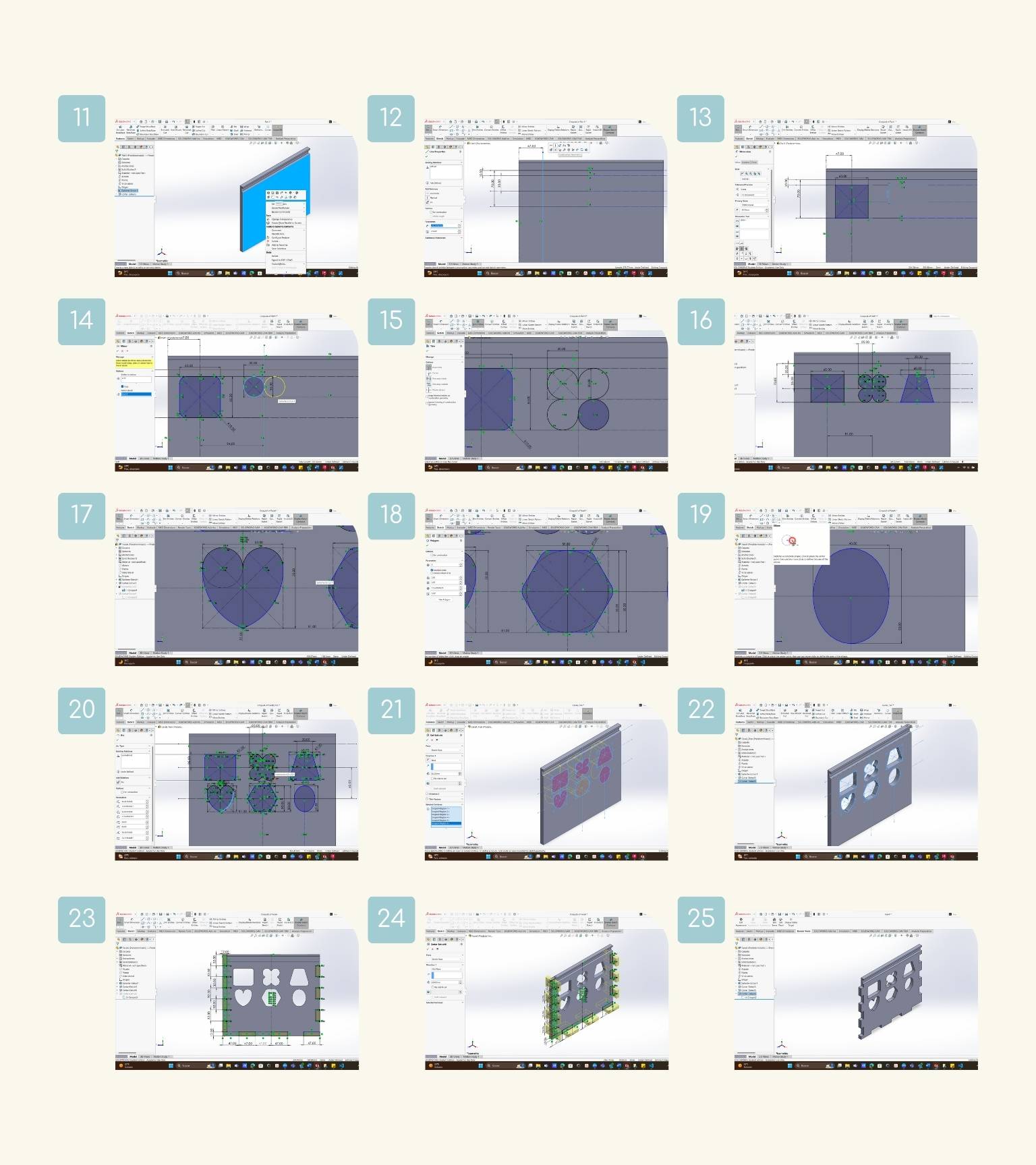
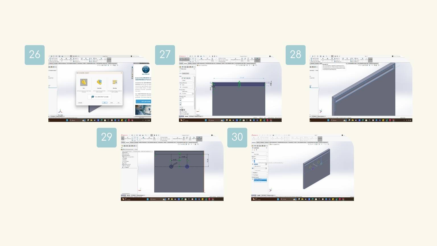
- I create a new part for a new piece.
- I draw a rectangle to the same dimensions as the first piece (282 mm x 236 mm) with an extrude of 12 mm. Then I draw the lip slide section.
- Then, I made a cut extrude with a measurement of 5 mm into the piece.
- I created a new sketch to draw two holes so that the wagons can be linked together with a rope.
- I drew four centerlines for reference to detect the center where I would draw the circles.
- I drew two circles of 20 mm diameter.
- I use the feature ‘Cut-Extrude’ to cut the circles.
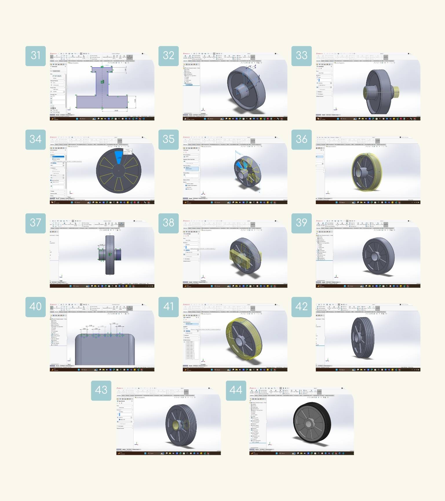
- As in the previous pieces, I created a new sketch to draw the silhouette of the tire.
- I made a ‘I’ with the centerlines and measurements that I show in the image.
- Then I revolved the figure around the tool ‘Revolved Boss/Base’
- This tool revolves a sketch or a selected sketch contour around an axis to create a solid feature.
- I made a sketch on the face of the tire axle to draw a circle that can be cut to form the hole.
- To cut, I used the tool ‘Extruded-Cut’.
- I created a new sketch to draw the patron of my wheel.
- When I drew the figure and extruded 3 mm.
- Then, I used the tool ‘Circle Pattern’ so that the same figure could be duplicated a certain number of times around the wheel.
- After, I applied a mirror to the internal face of the wheel.
- On the side plane, I created a sketch to draw the contour of the silhouette of the band.
- I drew a rectangle to 4 mm in height and the same width as the wheel. And applied a fill of 2 mm in the upper corners.
- Then I revolved.
- I drew in a new sketch a rectangle of 10 mm in width and 24 mm in height.
- I used the ‘Cut-Extruded’ to cut the excess of the tire axle.
- We have a more proportional wheel!
- I drew in the side view some rectangles of 2 mm in weight and 1 mm in height on the upper edge of the band.
- Note: The first rectangle is a figure, the next is a construction geometric, and so on.
- Then, I applied the tool ‘Cut Revolve’ .
- This tool cuts a solid model by revolving a sketched profile around an axis..
- After, I had the pattern applied.
- To make the hole in the tube thinner, I drew two circles: one 15 mm in diameter and the other 20.2 mm. And then I made an extrusion along the axis.
- And the wheel was ready!
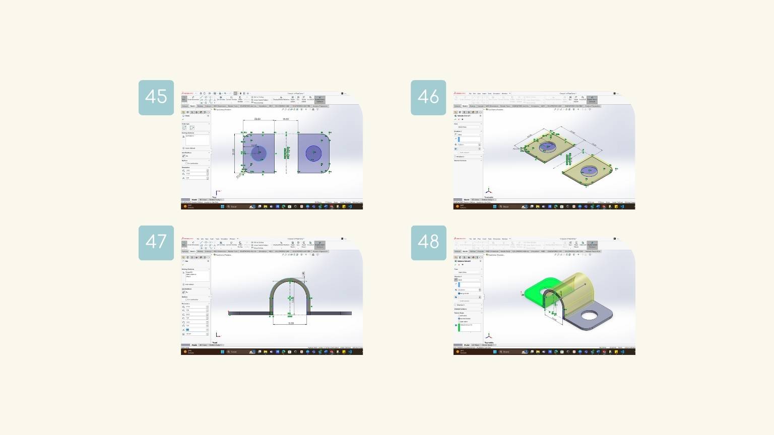
- In a new part, I created a sketch of the plant plane. And I drew a rectangle with 20 mm of width and 25 mm of height.
- Then, I drew a circle of 5 mm in radius at 10 mm from the left lateral side.
- I applied a fillet of 5 mm to the left lateral corners.
- Lastly, I applied a mirror to the drawer.
- I extruded the figure at 1.5 mm.
- After, I made a sketch in the front plane to draw an arc to allow the entry of the shaft tube.
- And then I extruded the figure at 25 mm. So, we have the pipe clamp!
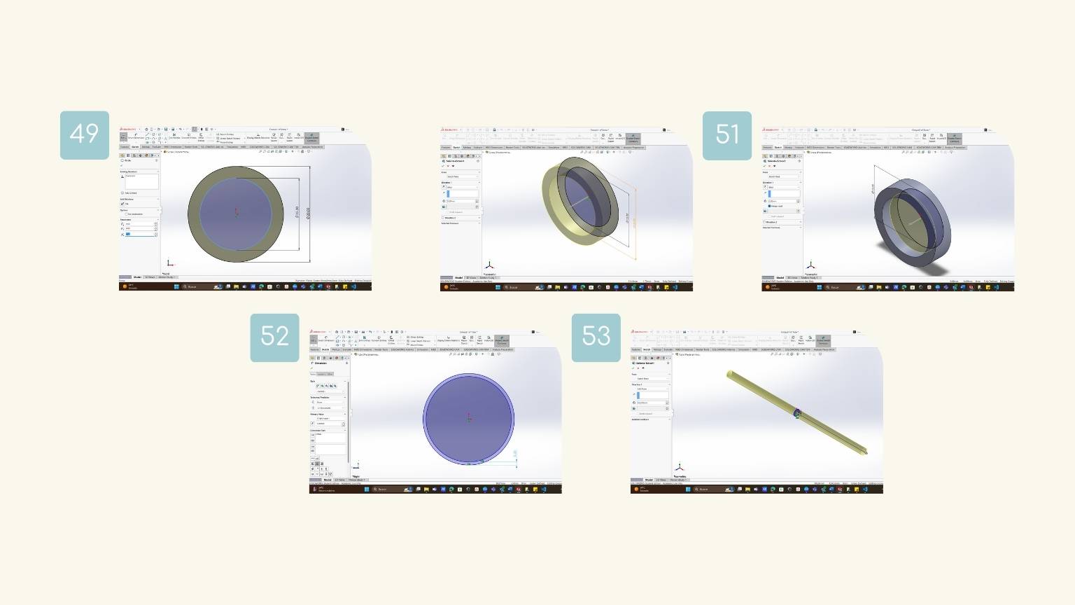
- In a new document, I drew two circles: one 15 mm in diameter and the other 20 mm.
- Then, I extruded 5 mm of the contour that was created by the two circles.
- In a new sketch, I drew a circle of 15 mm in diameter for later extruding 2.5 mm.
- For a new part, I drew a circle of 15 mm in diameter and applied an offset of 0.5 mm to the inside of the circle.
- Finally, I extruded the sketch in a mid-plane direction with a length of 352 mm.
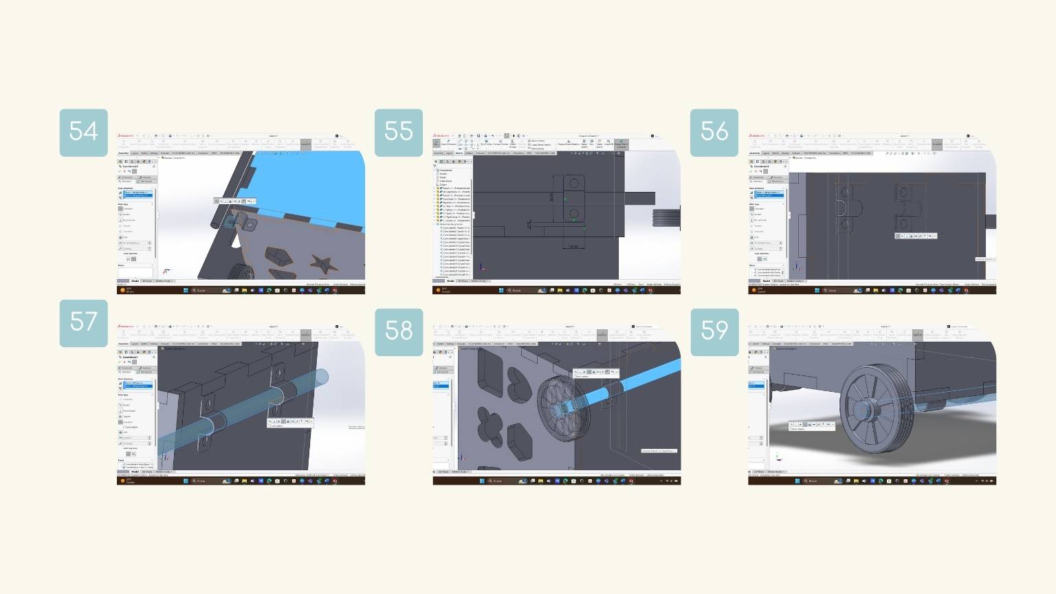
- So, basically, I used the ‘Coincident’ to delimit which faces were to match.
- I made some sketches to delineate some spaces that would occupy certain pieces.
- I used 'Concentric' to insert the tube into the wheel axle.
- For the moment, I only made use of these two functions to finally assemble my last component.
SIDE PIECE
Lib Slide Section
Figures on the face
Rectangle
Flower
Trapeze
Heart
Hexagon
Oval
Cut-Extrude
Assemblies
Back Piece
Holes
Wheel
Axle Hole
Pattern
Band
Axis
Pattern Wheel
Axel Hool
Pipe Clamp
Stopper
Tube
Assembly
Once all the parts were done, I opened a new document, 'Assembly', to unify all the parts and show the product with all its components. In the document, I used the 'Mate' tool for creating geometric relationships between components, to define the allowable directions of linear or rotational motion components.
Final Result
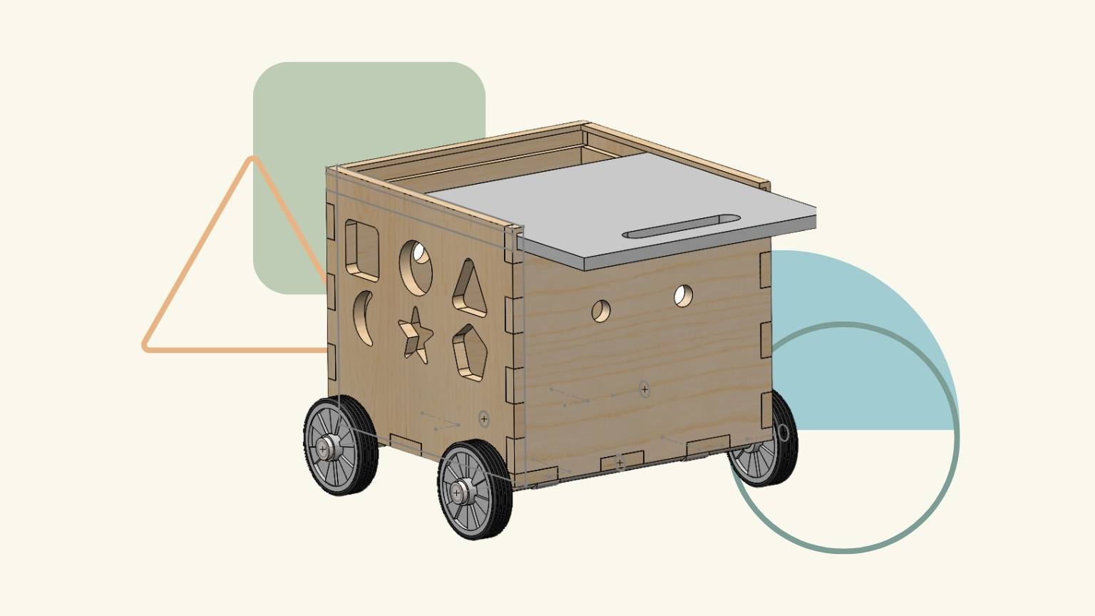
Modeling my final project … or something like that
Why Rhino?
I chose to use Rhino because it is the most recent program I have experience with. I think it's a really user-friendly program that allows for experimentation and easy modeling of ideas.
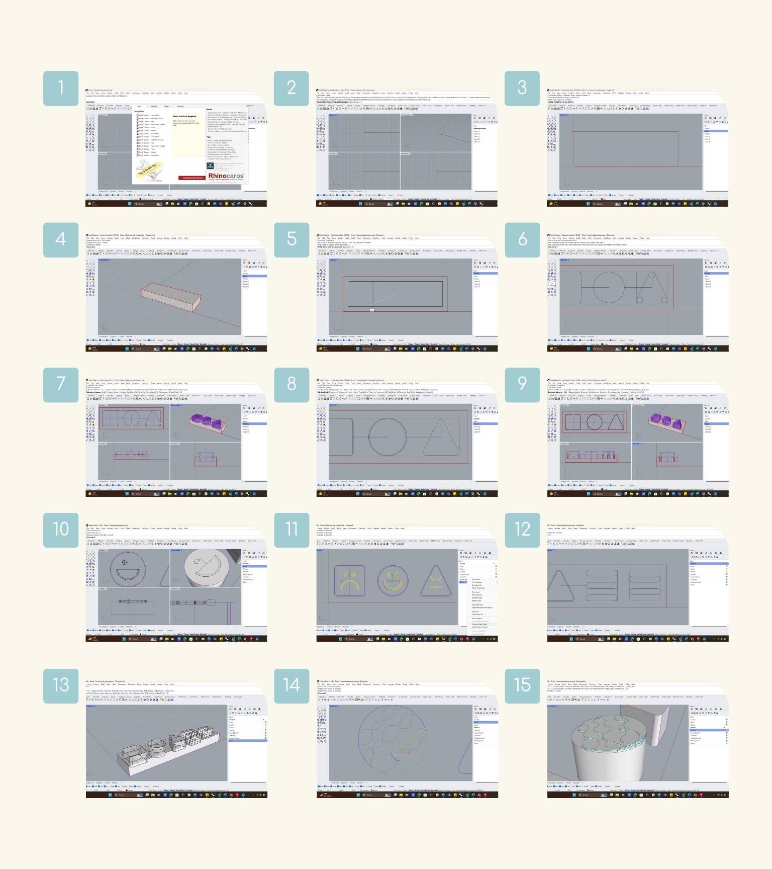
How did I use it?
For my final project, I decided to use Rhino to model and experiment with the shapes and dimensions of the different elements.
- First, I choose to work with small objects—centimeters.
- I choose the perspective that I use to make my first element.
- I chose the top perspective, and I double-clicked to select it.
- Then I made a box with 21 cm of length, 8 cm of width, and 3 cm of height.
- I looked at the box from a different perspective and changed the preview of the element to a shaded view to see the element in a better way.
- I made a rectangle, starting with the center.
- Star modeling the three basic shapes.
- Note:I made the shapes in a difficult way because I didn’t remember the tool to doing them in an essay.
- I started by making the square, then I made 4 circles in each corner so that the edges of the cube weren’t sharp.
- And the same with the triangle.
- I extruded the shapes 1.5 cm for both sides to have a shape of 3 cm.
- And I made a ‘Boolean Difference’ to cut the shapes in the base..
- Then I offset the contours of the shapes by 0.1 cm.
- After, I extruded these new shapes to allow the parts to fit without needing to be forced.
- I began to exploit a little bit the textures or reliefs that the figures could have.
- First, I made some faces related to the color and emotion that each figure represents (here I made a mistake regarding the faces, but it was corrected later)..
- I made three different expressions.
- I also explored a bit with the base, creating one that included two more colors. And I started by creating a sketch of the shapes and then extruding them.
- I made a ‘Boolean Difference’ to cut the news shapes in the base. And I extruded the shapes, considering the offset.
- Finally, I explored a different type of relief in the shapes.
- created a series of waves, which I extruded into sections.
But this is just the beginning...
Problems with Fusion 360
And I would have liked to explore Fusion 360, but it was not possible due to a problem with the installation of the program on my computer. So, I will try to be able to solve it in order not to leave aside the exploration with it.
Conclusion
In both SolidWorks and Rhino, I initially created my figures in a more complex manner. However, I later discovered a tool that simplified the process, ultimately saving me time. This experience helped me to become more familiar with the different tools and reinforced the importance of having a clear idea of what I wanted to achieve before beginning the modeling process. By doing so, I was able to better understand the steps required to achieve my desired results.
I wanted to bring up this last point because, when it came to my final project, I wasn't quite sure what it should look like, what mechanisms and systems to integrate, or what size to make it. This left me with a lot of questions, but it also inspired me to learn what I needed to know and start thinking and researching in order to bring my proposal to life.
2D Design
For this, I utilized Adobe Illustrator, the industry-leading graphic design application that allows you to design and customize everything you can think of, from logos and icons to graphics and illustrations, with professional precision.
Some of your features include:
- Combine lines, shapes, and color to design incredible illustrations.
- User-Friendly Interface.
- It’s an industry-standard design tool used by professionals.
- It provides a large number of keyboard shortcuts that can significantly increase your productivity with the product.
- 3D features enable users to create engaging three-dimensional forms and images, thereby improving the visual attractiveness of their work.
- Design illustrations with precision.
- When you hover your mouse over a tool, an option appears to learn more about its use and the steps to use it.
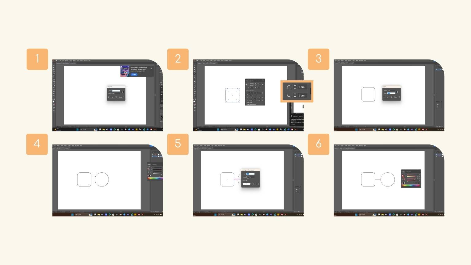
So, I wanted to share with you the three primary shapes I created, drawing inspiration from my final project. Here are the steps I followed:
- I opened a new file, and first I created a rectangle measuring 5 cm.
- To do this, I used the ‘Polygon’ tool. I opened the tool scale, selected the tool, and double-clicked it to make the shape.
- When I created the rectangle, I decided to make the corners rounded with a measurement of 1 cm.
- Then I created a circle with the same measurement (5 cm in diameter).
- And we have a square and circle!
- I made a line of 2 cm as a guide to determine the distance between each shape.
- I put the line in the middle of the height of the rectangle, and I moved the circle to the right so that the line and the shape intersect.
- After, I followed the steps to place an image.
- I selected the image for my archives, and I put the image in the file.
- I resized the image and added transparency.
- I made this in the section of ‘Proprieties’ in the right menu.
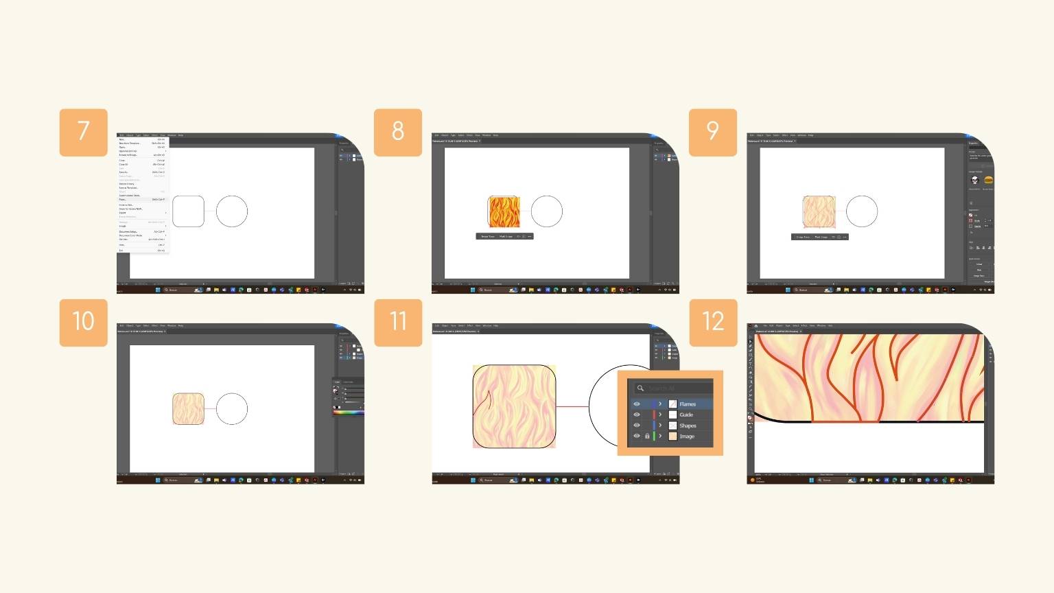
- I placed it aligned to the shape previously made to start tracing the “flames”.
- After, I started to make the strokes based on the image.
- To stroke, I used the ‘Pen’ tool, which helps you to manually draw lines, shapes, and straight and curved edges.
- Important: To make a curve, you have to define the first point, mark the middle point, and keep the click pressed to determine the curvature of the line. Finally marked the final point and continued the draw.
- While tracing. I was closing the created shapes to later put a fill color on them.
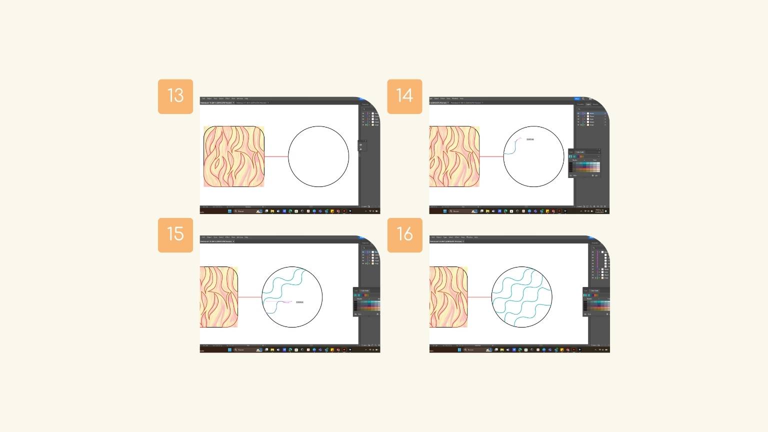
- Now I will start tracing the waves in the circle.
- To create this texture, I used the ‘Pen’ tool again.
- And I made the curves with the same steps to create the “waves.”
- We have our waves ready!
- To create the triangle, I made a rectangle of the base.
- Then, I used the ‘Polygon’ tool to make the triangle.
- In the parameters, you will define the number of sides and the radius you desire.
- I rounded the corners with a radius of 0.5 cm.
- I redetermined the measurements of the shapes.
- Note: I couldn’t get the figure to be exactly 5 cm, due to the nature of the figure and the rounding.
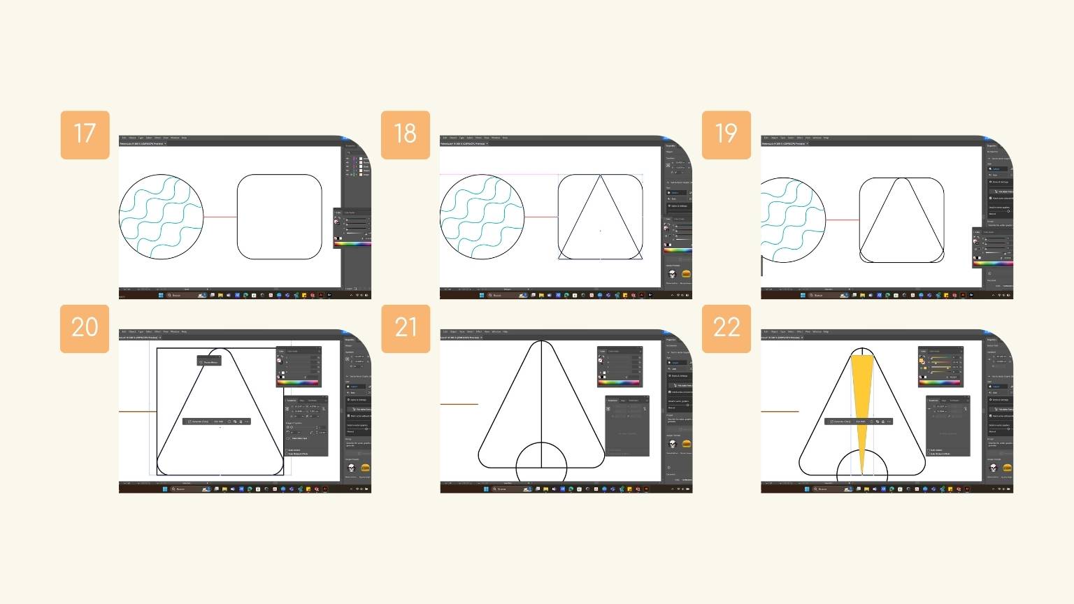
- I drew a middle line, and in the base of the triangle, I created a circle of 2 cm as a guide for my nest strokes.
- I made an inverted triangle, taking as a base the length of the rounding and considering it as the center of the circle.
- After, I used the ‘Repeat’ tool, especially the ‘Radial’ option.
- This tool has the function of distributing the object around a central point.
- Note: You will have to have the figure selected for the pattern to be made.
- To modify the parameters, I went back to the ‘Object’ menu, went to 'Respeat', and selected the last option, ‘Options’
- I put 29 objects to be repeated with a radius of 3 cm.
- Then, I selected all the objects repeated and the silhouette of the triangle and used the ‘Pathfinder’ tool to make a ‘Divide’ of the shapes to eliminate unwanted leftover elements.
- Note: Make a copy of the triangle because the following operation will also be applied.
- I deleted all excesses.
- And finally, I deleted the circle of reference, so we have the silhouette of sunshine.
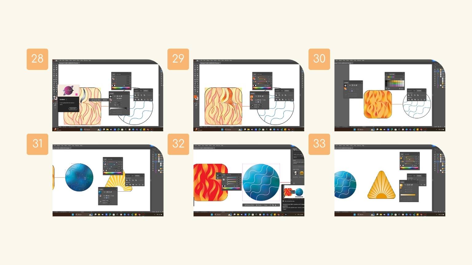
- To apply a fill of color to the shapes, I decided to make a gradient.
- The use of the ‘Gradient’ tool is to create a gradual bled between colors.
- I chose the freeform gradient type and started to change the stroke, aspect ratio, and opacity.
- And I added a fill color to the square.
- I did the same steps with the circle to make a gradient fill.
- I changed the color of the waves.
- Finally, I applied a gradient to the rays and a color fill to the triangle.
Square and Triangle
SHAPE: FLAMES TEXTURE
CIRCLE: WAVE TEXTURE
TRIANGLE: SUN RAYS TEXTURE

COLORING THE SHAPES
Final Result

Conclusion
I chose Adobe Illustrator because it's the tool I'm most familiar with, and I didn't have a lot of time to finish the assignment without falling behind on the next one (nervous laughter).
However, it's a versatile and intuitive software with a great reputation. It's important to note that it's a paid software, but there's a similar free alternative called Inkscape. I'll be providing instructions on how to use Inkscape soon… I promise!