12. Input device
What is an input?
Have you ever wondered what all the small devices are for? They're called input devices, and they're quite awesome! They act as an intermediary between the outside world and your computer. They convert all of the data you submit into machine-readable and intelligible format. That way, your computer can digest information and perform a variety of great tasks with it. So, the next time you use your computer, consider all of the input devices you use to make it work for you.
Group Assignment
Visit our group task by clicking on the button below.
What did I do this week?
I decided to use an infrared sensor to detect the movement.
But what is an infrared sensor?
An infrared sensor (IR sensor) is a radiation-sensitive optoelectronic component with a spectral sensitivity in the infrared wavelength range of 780 nm–50 µm. IR sensors are now widely used in motion detectors, which are used in building services to switch on lamps or in alarm systems to detect unwelcome guests. In a defined angle range, the sensor elements detect the heat radiation (infrared radiation) that changes over time and space due to the movement of people.
Sensor Design
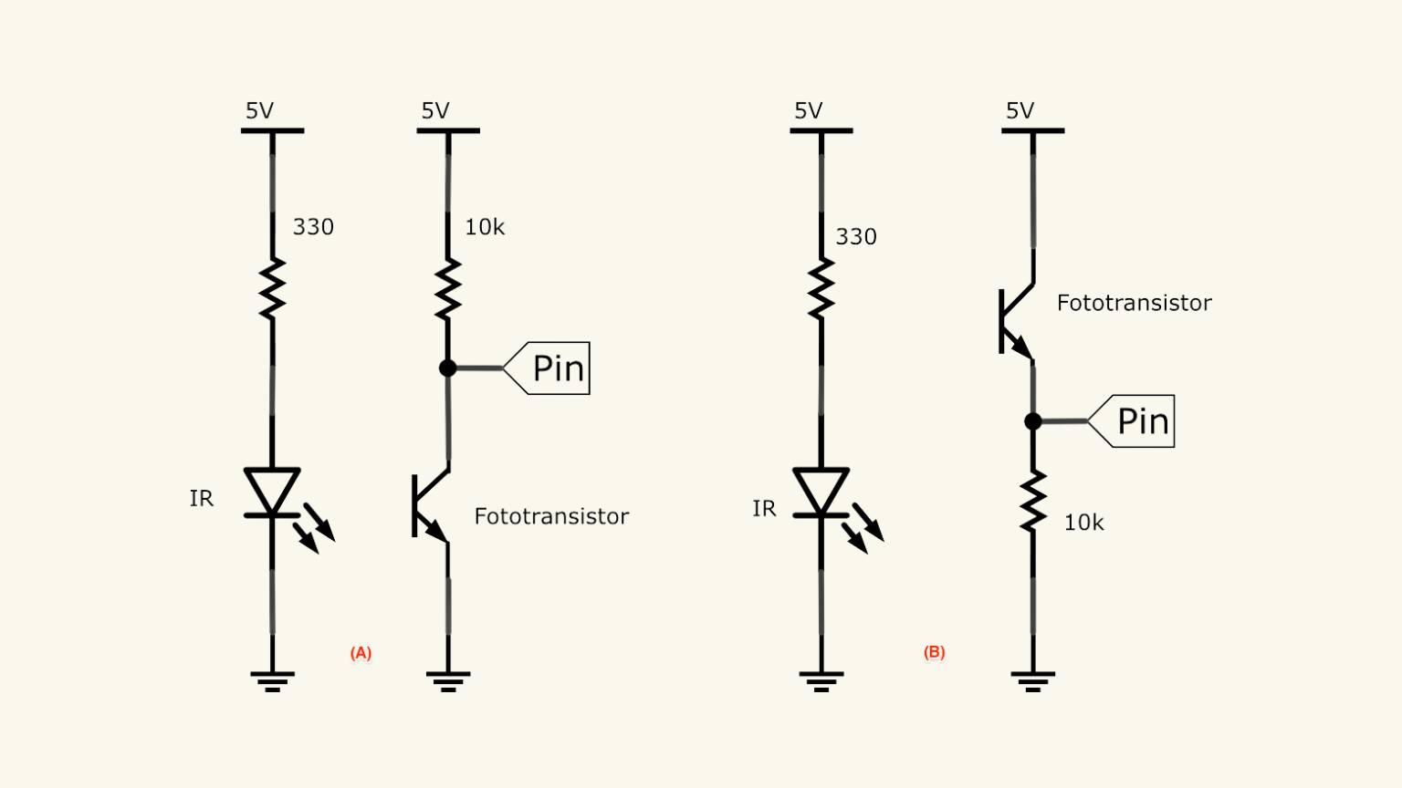
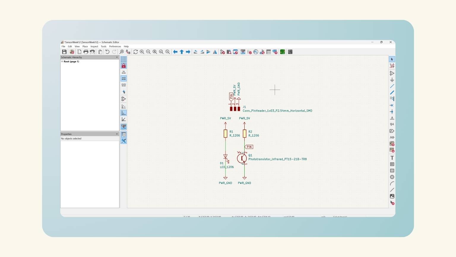
I designed the board that would function as my sensor based on the following schematic:
Steps:
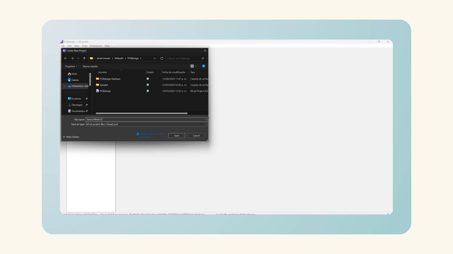
- So, I opened KiCad to design the sensor.
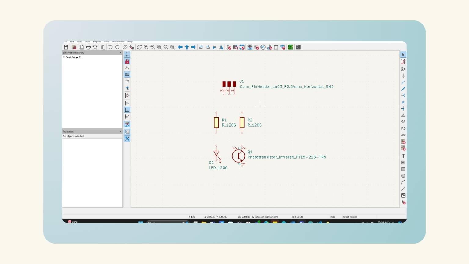
- I added all the components that I needed.
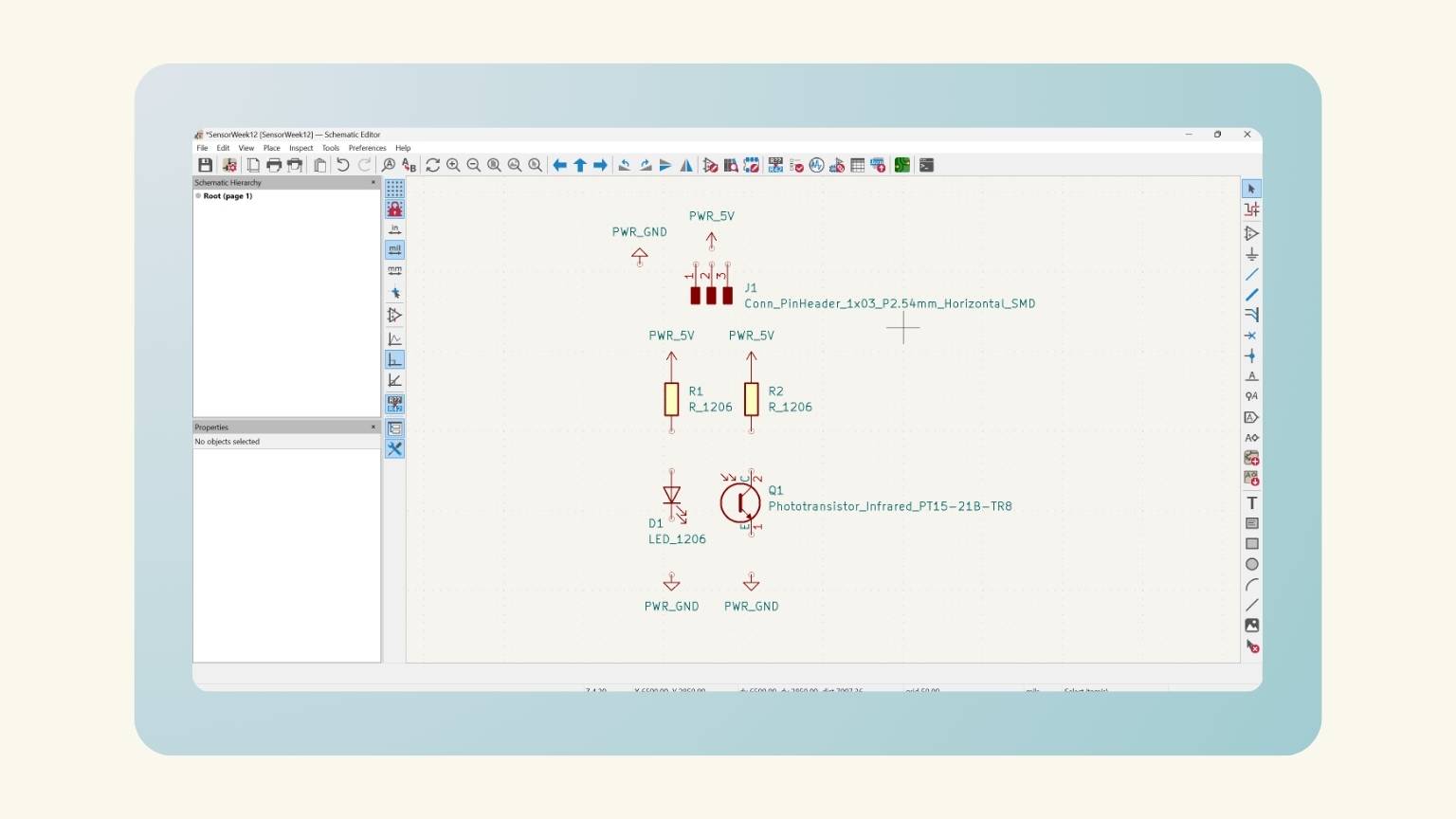
- I added the power symbols and connected them with the respective components.
- Then I made the connections between the components. .
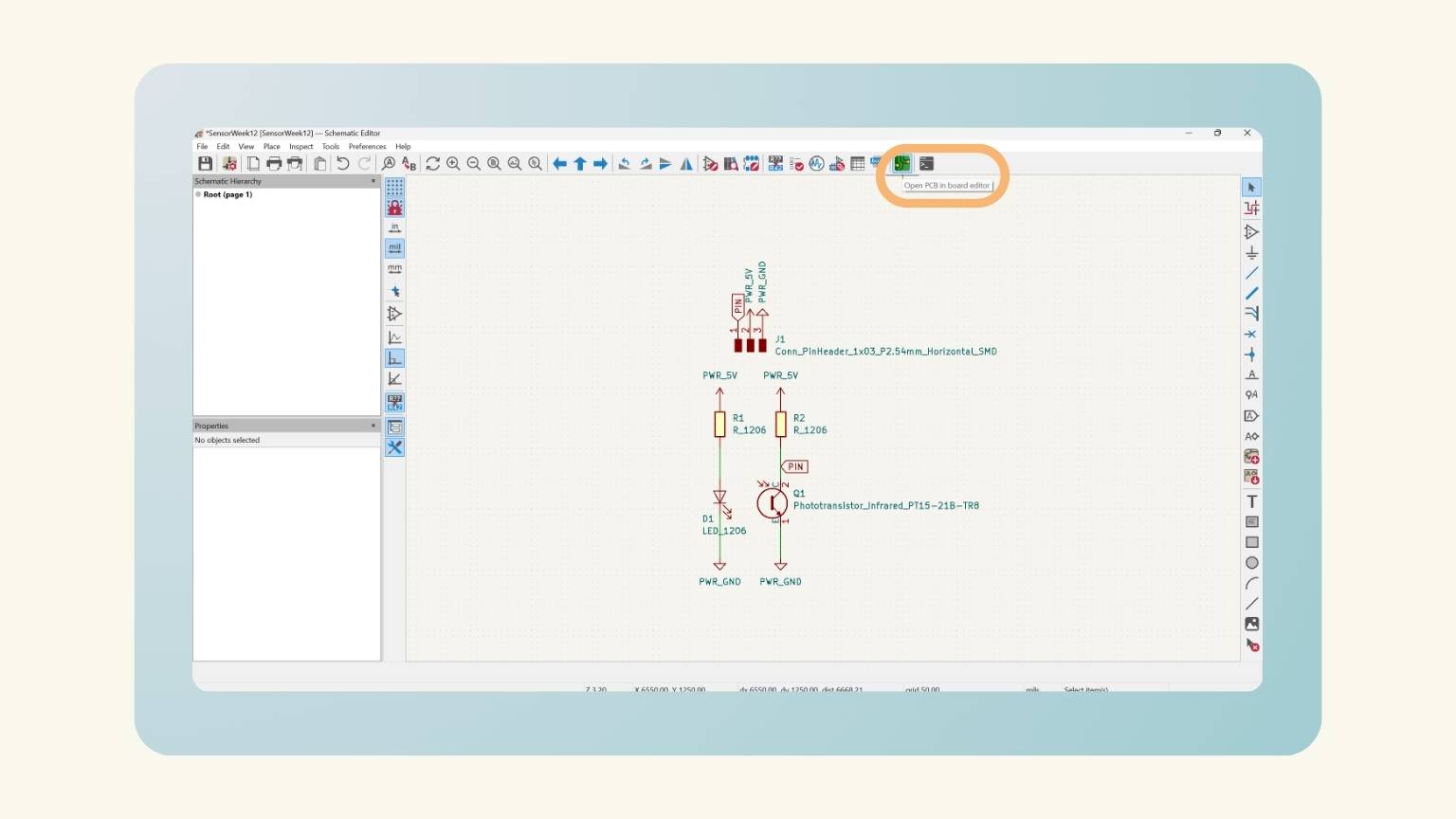
- I passed it on to the PCB editor to complete the design.
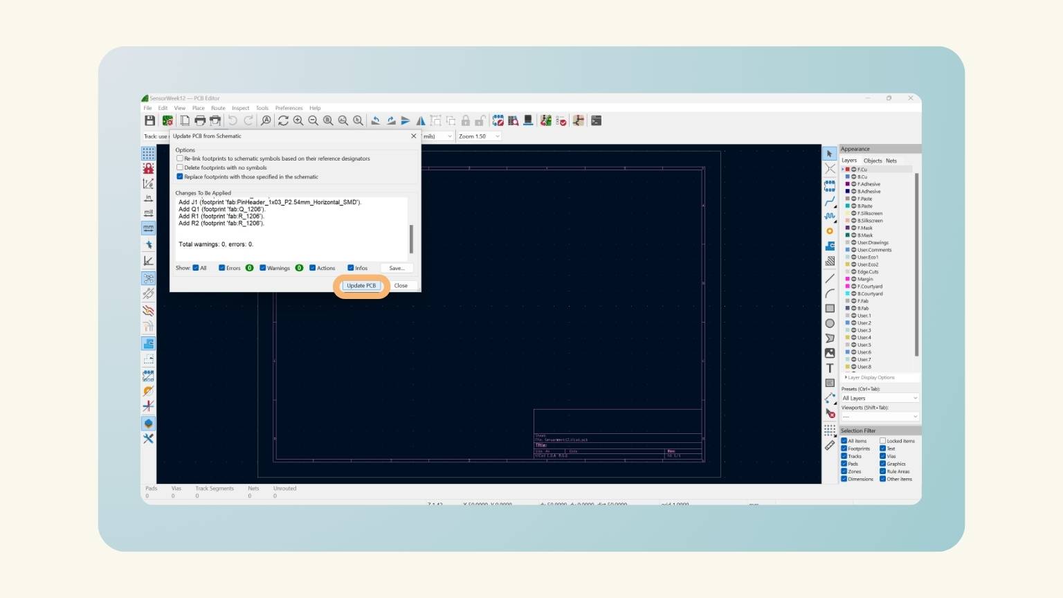
- I updated the PCB from the schematic.
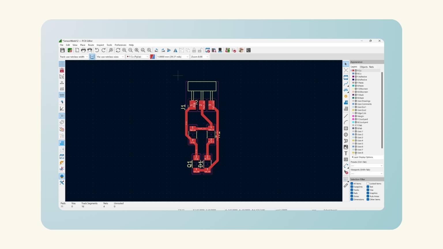
- I organized the components to make the traces and connections.
- I made the framework.
- Next, I saved the strokes first, and then the outline.

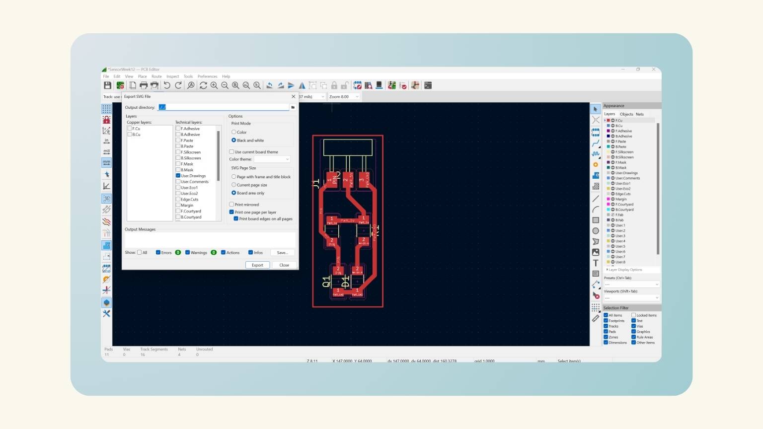
Sensor Production
Recap
The machine used for the creation of the PCB is...
ROLAND SRM-20
This machine can cut a broad range of materials, including chemical wood, acrylic, and ABS. It also supports a wide variety of accuracy settings, from prototype to product design. Furthermore, its tiny size and fully enclosed design allow you to cut with greater safety and confidence.
What tools will we use?
V-Cutter, allows for better engraving for its fine tip.
Flute end Mill, for drilling and plate cutting.
To prepare the control software, I used...
Mods
A program that allows me to extract G-codes or machine codes from images, vectors or 3d models.
Mods Time
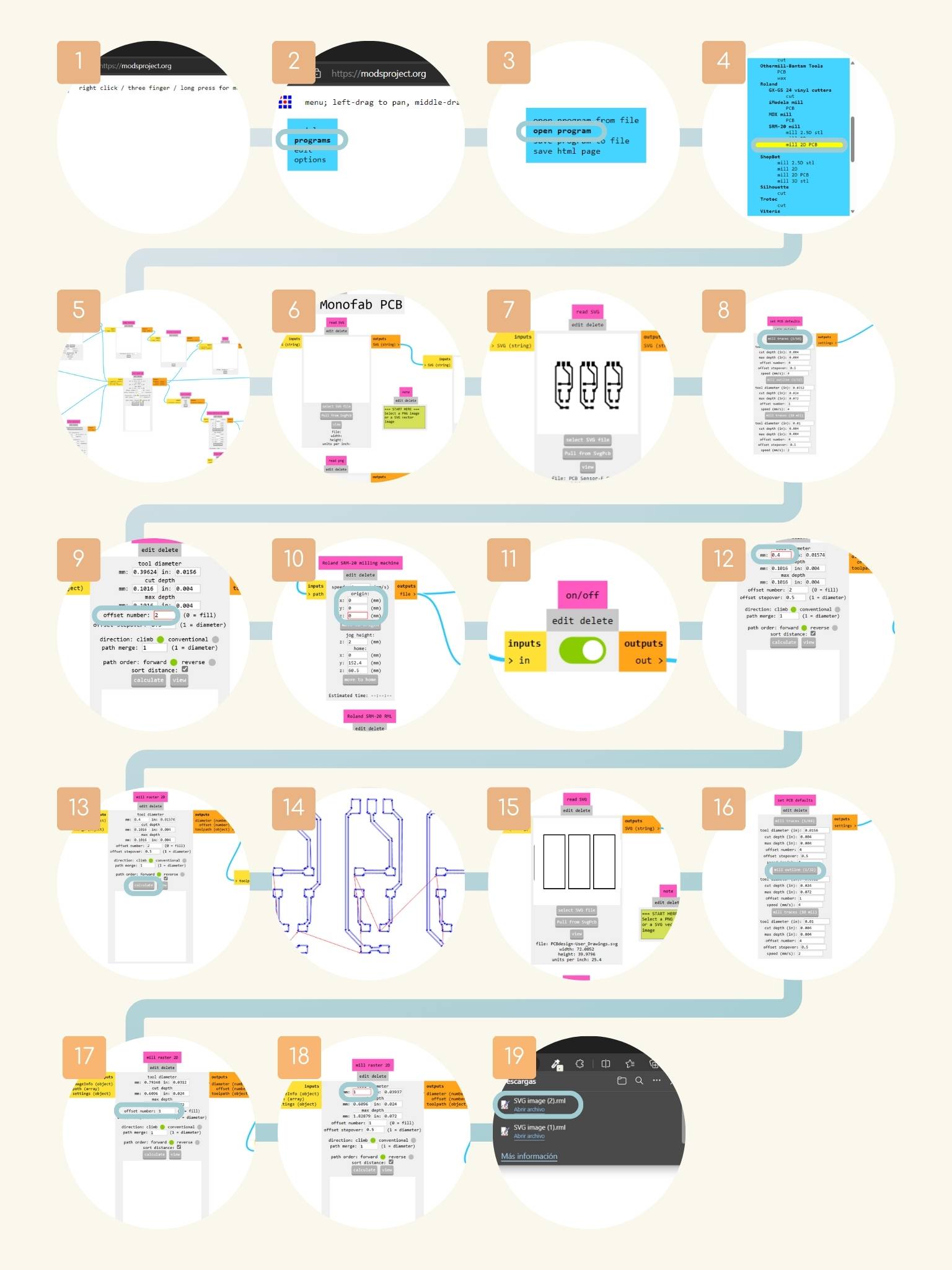
- I opened the MODS web server.
- I right clicked on ‘Programs’
- Next in ‘Open program’
- I searched the program of the SRM-20 mill machine and selected the ‘mill 2D PCB’.
- All the blocks to be worked on are displayed to obtain the corresponding files.
- The first block that I modified is the 'read SVG’ block for selecting a SVG file.
- I saw that the image was uploaded to the server.
- I moved to the ‘set PCB defaults’ block and pressed ‘mill traces’.
- I moved to the ‘mill raster 2D’ block. And I changed the ‘offset number’ to two.
- Then, I went to the ‘Roland SRM-2D milling machine’ block, and I modified the origin of the machine. For this, I changed the numbers on the axes x, y, and z.
- I moved to the right and turned on the ‘outputs’.
- I moved to the ‘mill raster SD’ and changed the tool diameter to 0.4 mm.
- And then I pressed ‘calculate’.
- And I saw a preview. In addition, in my downloads, I found an archive ‘.png.rtl’; this is the file that I opened on the machine.
- Next, I did the same steps with the SVG of the cut. Starting by selecting the cut SVG of my files.
- I moved to the ‘set PCB defaults’ block and pressed ‘mill outline’.
- Then, I went to the ‘mill raster 2D’ block and changed the ‘offset number’ to one.
- I moved to the ‘mill raster SD’ to change the tool diameter to 1 mm.
- And I pressed calculate to see the preview of the cut and downloaded the file for the machine.
Cut Time
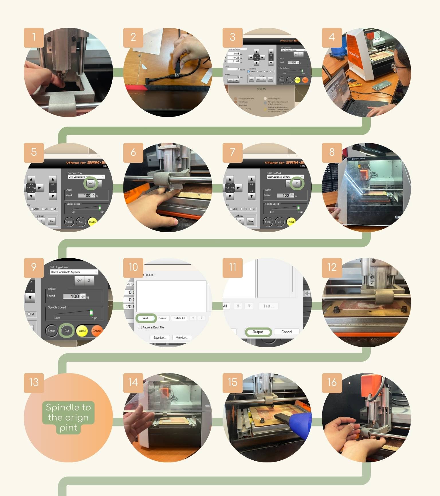
- I placed the tool, a 15 degree V-bit, to make the engraving.
- To do this, I used a wrench to tighten the tool.
- Note:Make sure that only the conical part of the tool protrudes.
- I connected the machine to my computer.
- I open the ‘VPanel for SRM-20’
- First, I moved the X/Y axis to the lower left of the material.
- And I pressed the ‘X/Y’ bottom to change the origin of this axis’s.
- Then, I moved the Z axis. To do this, I used a piece of paper to make sure I put the axis at the correct height.
- For this special axis, I used a paper to define the distance between the tool and the material. I did this by placing the paper on the material and lowering the tool a little at a time until the point where friction is generated and the paper gets stuck.
- Note: In this axis, before we did the paper check, we had to turn on the spindle and lower the z-axis, giving only one click to selecting ‘x10’ in the cursor step.
- I save the origin of the axis by pressing ‘Z’.
- When I defined the axis of origin, I closed the door of the machine.
- Then, I pressed the 'Cut' button at the bottom of the panel.
- I added the file to be engraved.
- I pressed ‘Outpt’ to send the file to be engraved.
- And the machine started to engrave.
- When the engraving was finished, the spindle went to the origin point.
- I opened the door of the machine.
- I used a hand vacuum cleaner to remove the dust produced by the engraving.
- I removed the tool that the machine had because it wasn’t the right one.So, I changed the previous tool to do the cut.
- For this, I used a wrench to tighten the tool.
- Note:Make sure that the conic part protrudes.
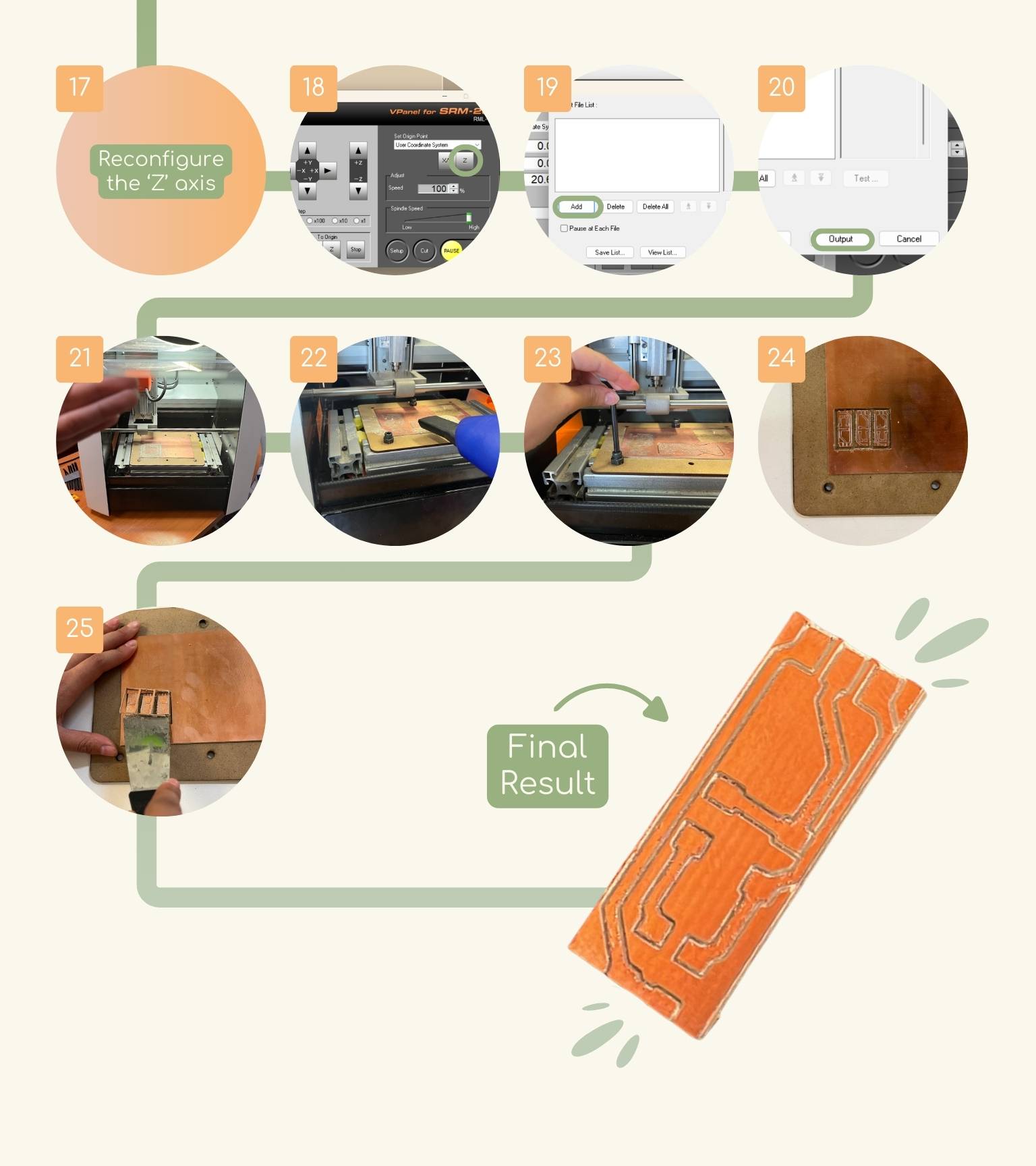
- I maintained the ‘X/Y’ origin and only changed the ‘Z axis’ because the tool was different and it was necessary to reconfigure that axis due to the height of the tool.
- I save the new origin of the axis by pressing ‘Z’.
- When I closed the door of the machine, I pressed the ‘Cut’ button to delete the previous file that I added.
- I added the new file of cut. And I pressed ‘Output’ for the machine to execute the cut.
- The machine started the cut.
- I used a hand vacuum cleaner to remove the dust produced by the cut.
- I removed the screws fixing the material with the help of a screwdriver.
- Finally, I had my newPCB!
Note:To move the axis fist, I used the ‘Continue’ cursor step, after the ‘x100’ (1 mm), then the ‘x10’ (0.1mm), and finally the ‘x1’ (0.01mm) until the paper generated friction and didn’t come off.
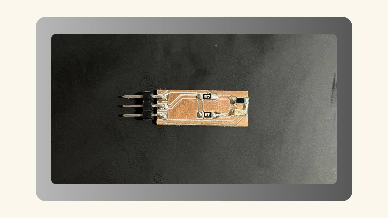
Soldering
Soldering time
- I soldered the phototransistor and the LED.
- I soldered two resistance, one to the phototransistor and the other to the LED.
- I putted a bit of soldering in the spaces destined to place the pins.
- Then, I soldered the pins.
- All the components were solder!
Programming
I started by performing a test of the sensor that I made with an Arduino one, then performing it with my board.
With the Arduino UNO:
- So, I connected the sensor to the Arduino.
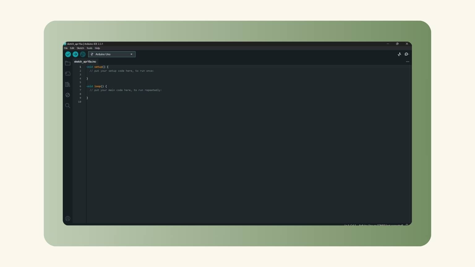
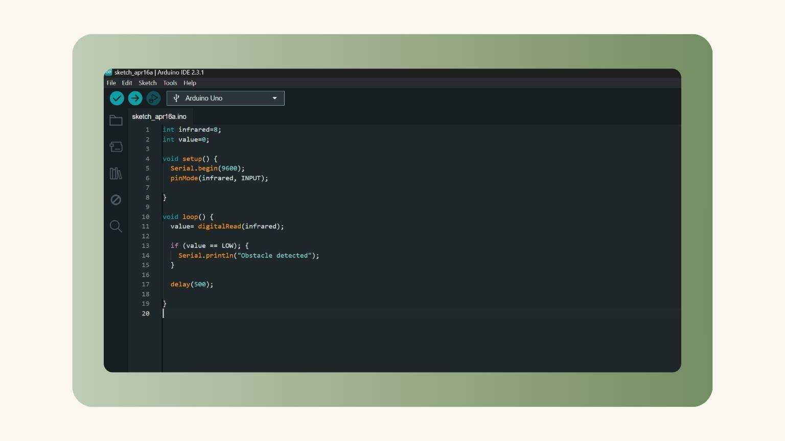
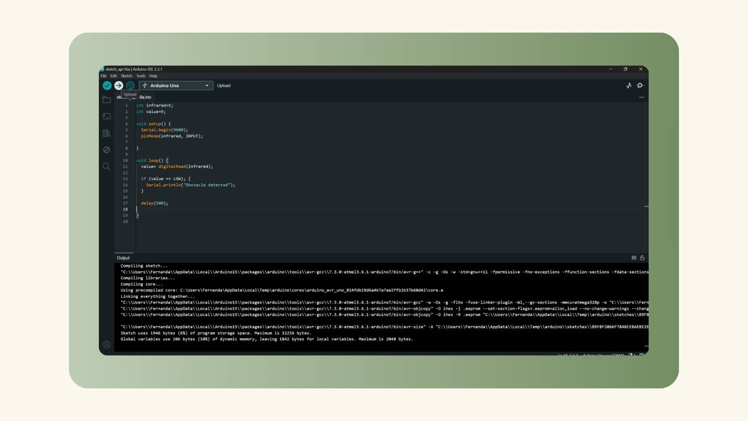
- I opened Arduino to start writing the programming.
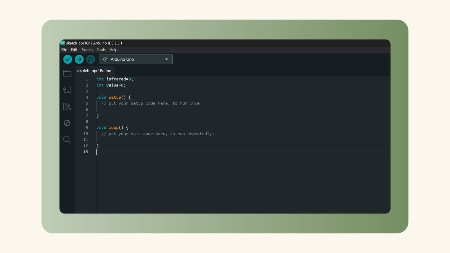
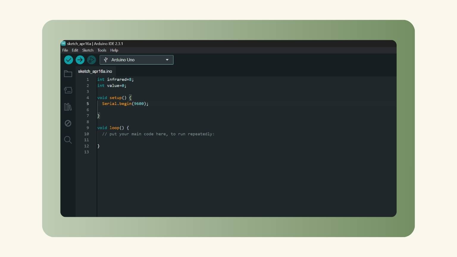
- First, I declared the infrared and the value.
- Then, in the ‘void setup’ section, I determined the ‘Serial.begin’ to 9600.
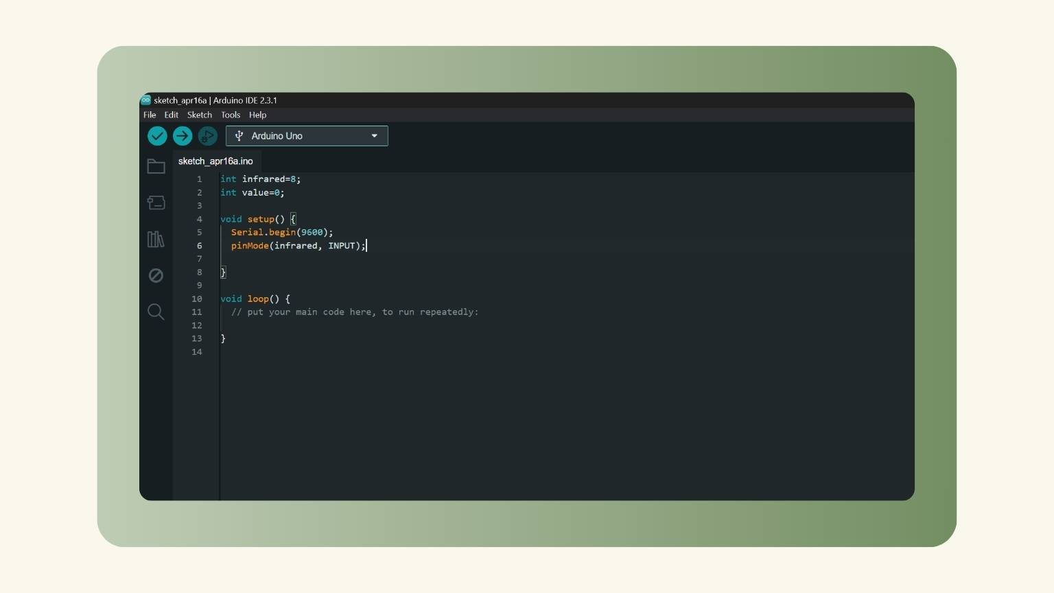
- I declared the infrared as an output.
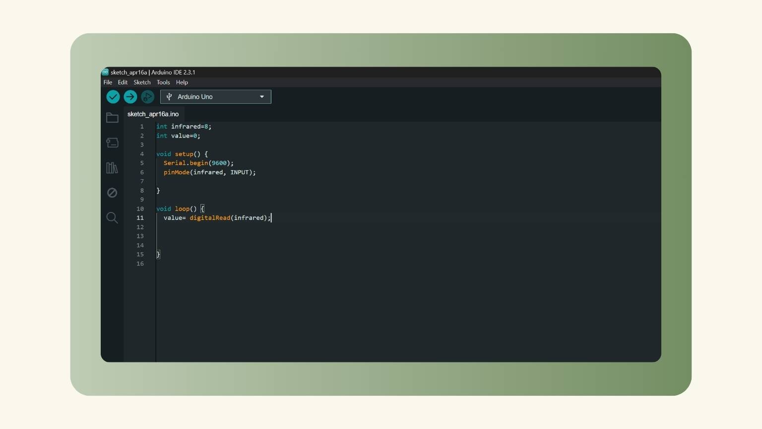
- Next, in the ‘void loop’ section, I declared the value equal to the ‘digitalRead’ of the infrared.
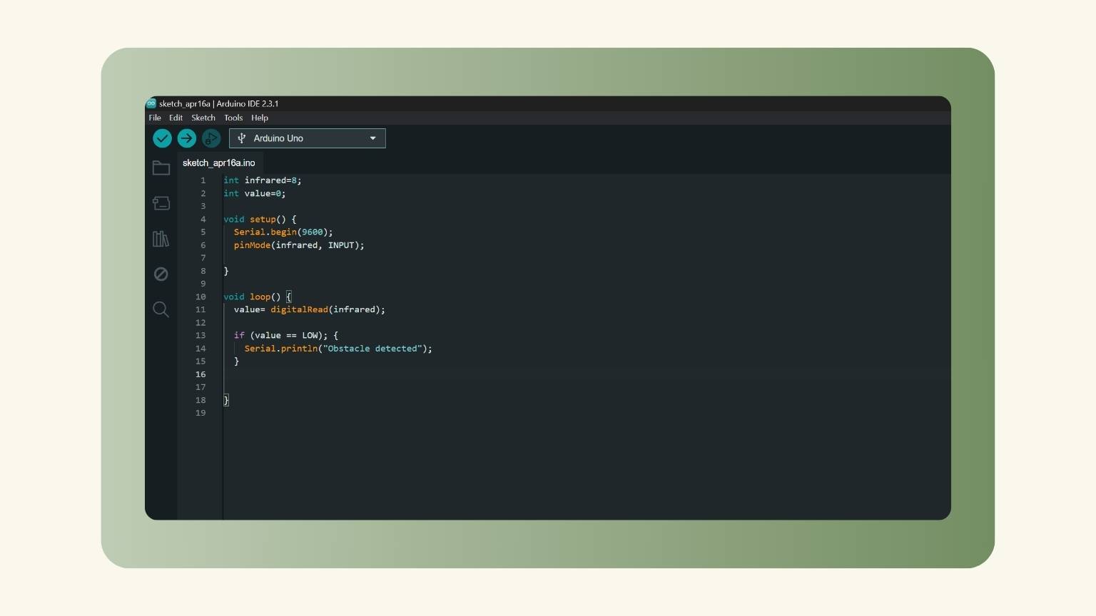
- After that, I wrote a condition. If the value was low, "obstacle detected" should be printed.
- I gave the action a duration of half a second.
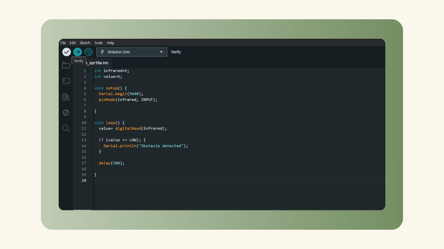
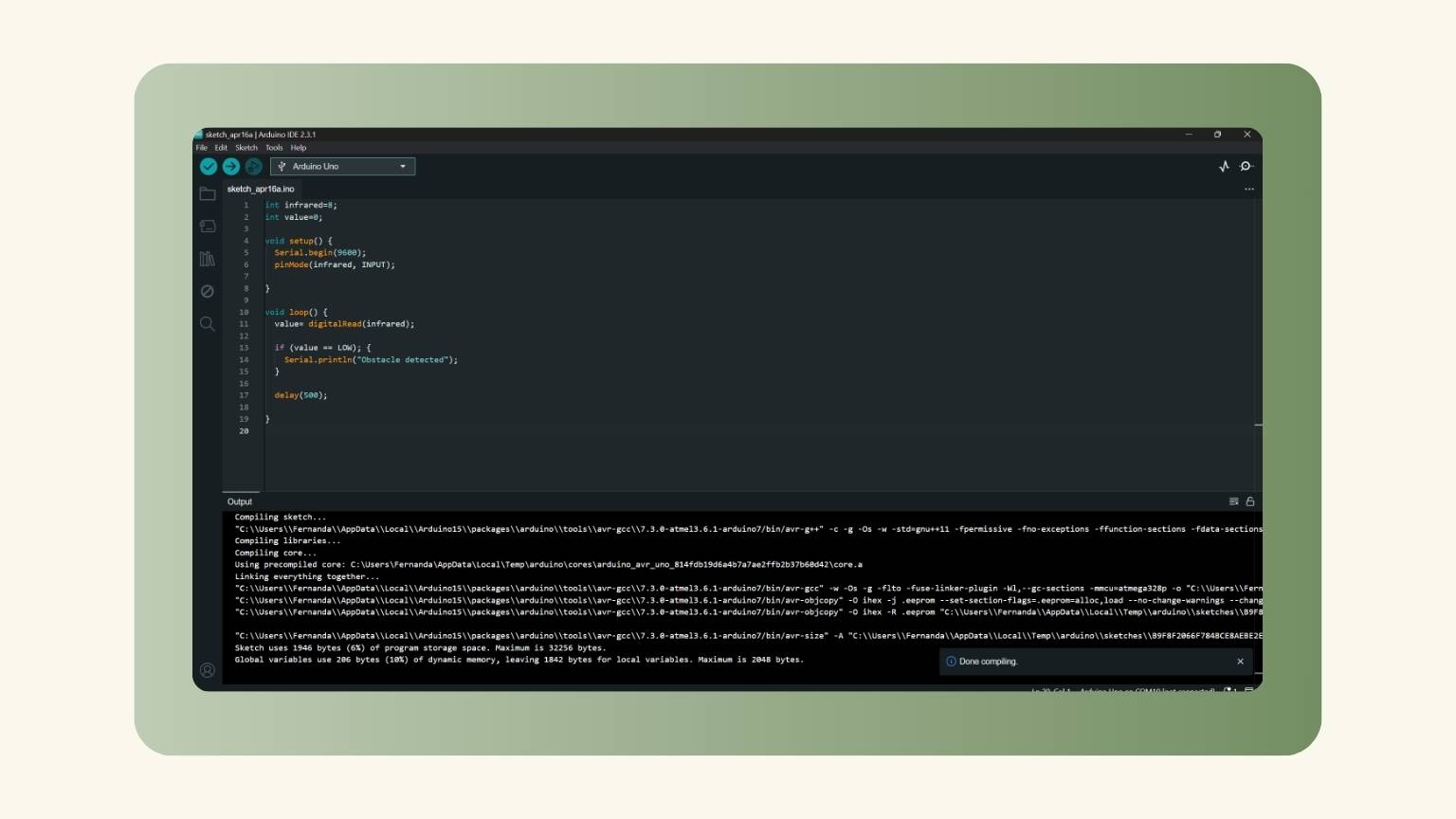
- I checked if there was an error in the programming.
- The programming was correct.
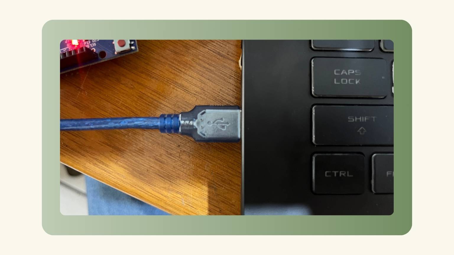
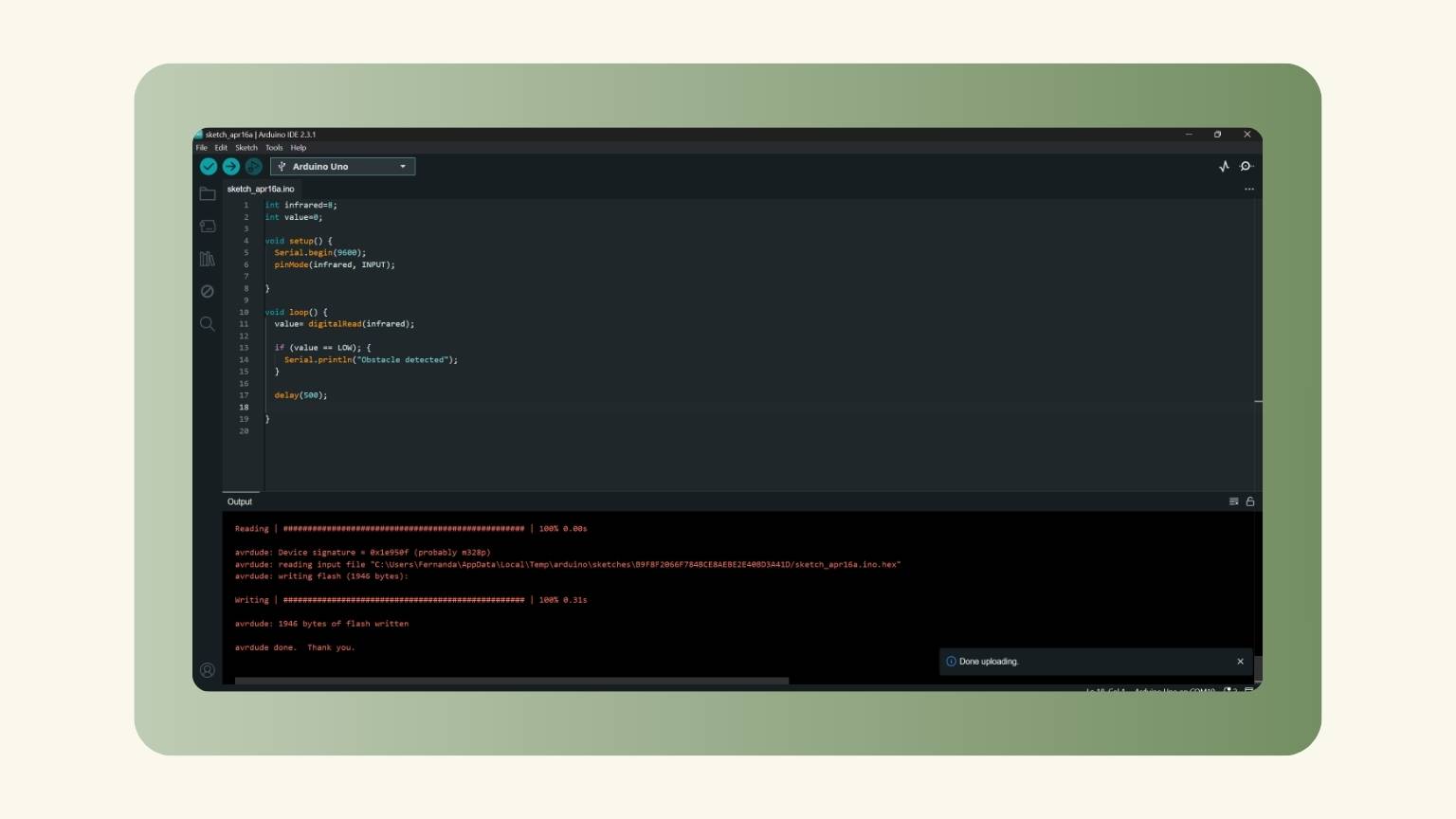
- I connected the Arduino to my computer.
- I loaded the programming on an Arduino.
- The programming was loaded.
- And this was the result:
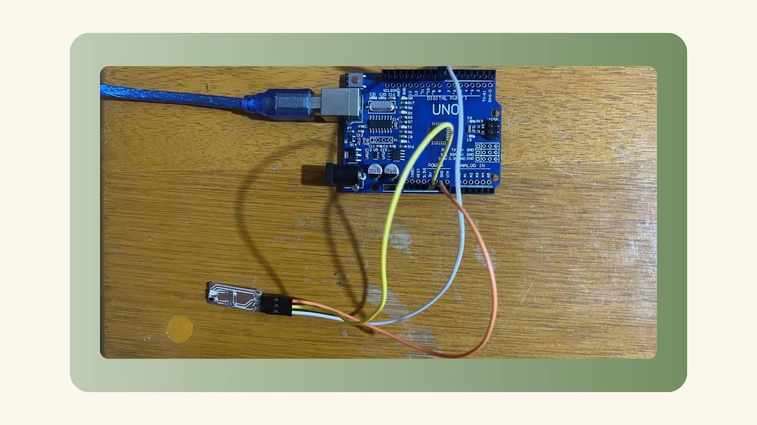
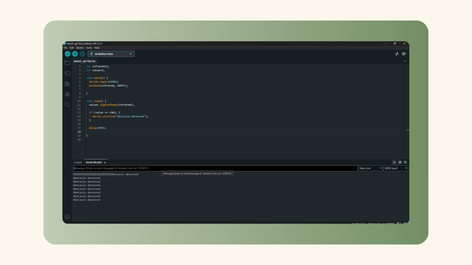
Note: I used the arduino to check that the sensor made would work.
CODE:
With the Xiao:
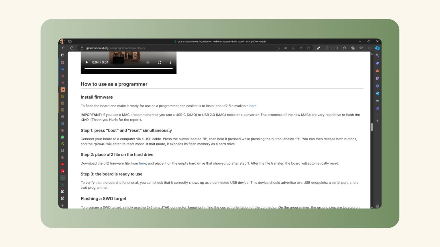
- First, I searched for how to use the Xiao as a programmer.
- I found the steps in the information about the Quentorres, and I followed the steps.
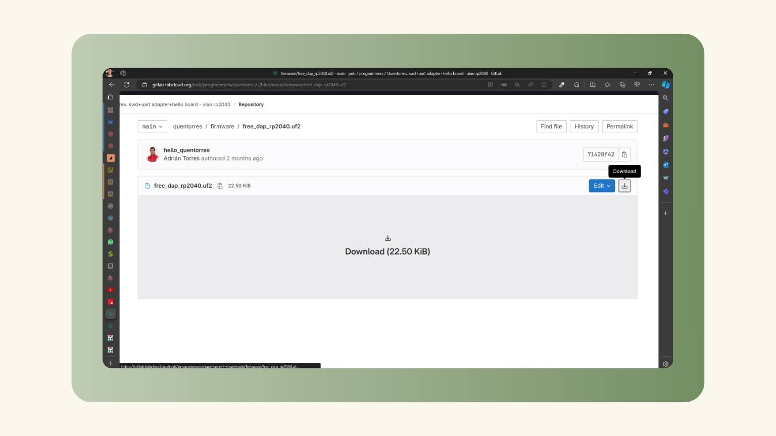
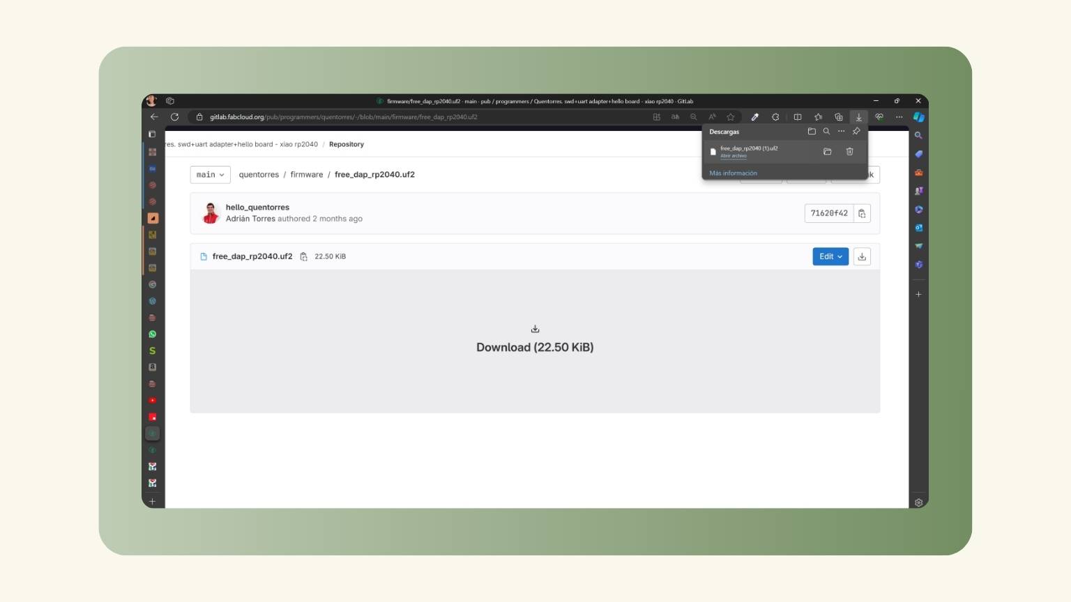
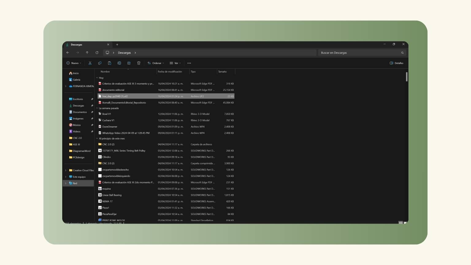
- So, I started to download the uf2 file.
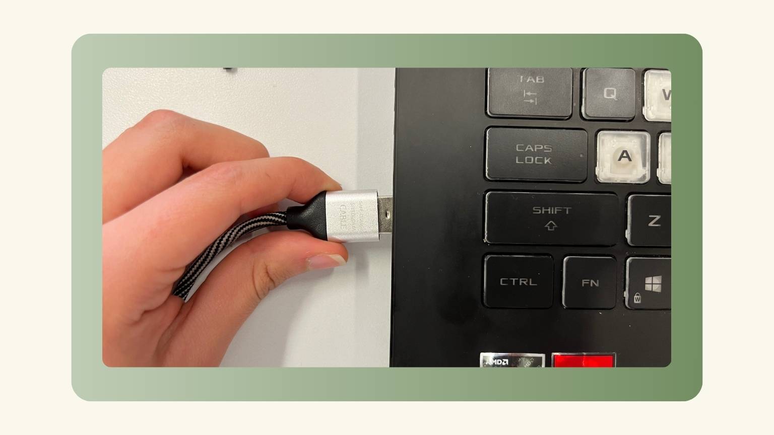
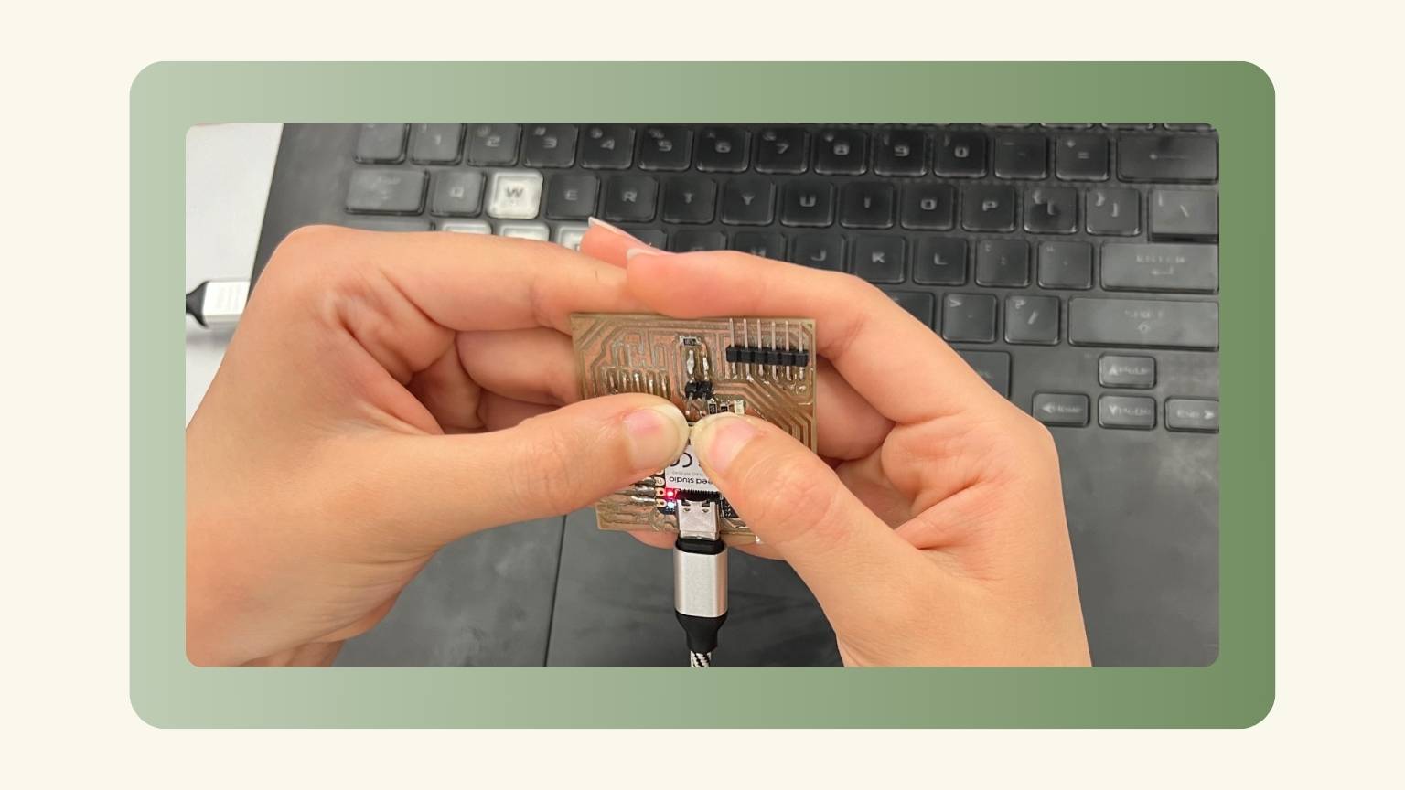
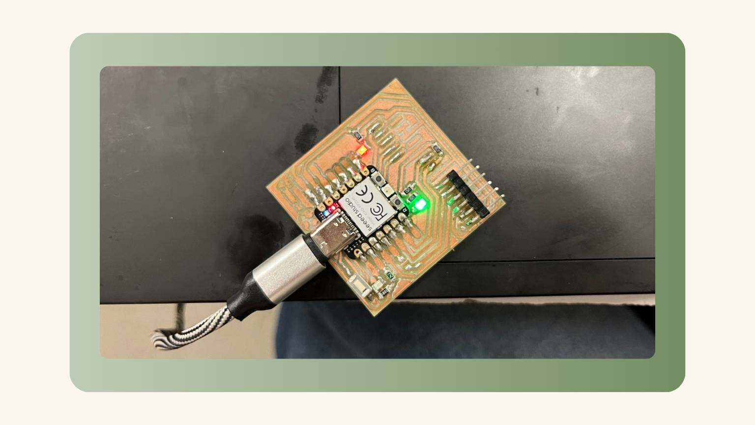
- Then, I connected my board to my computer via a USB cable.
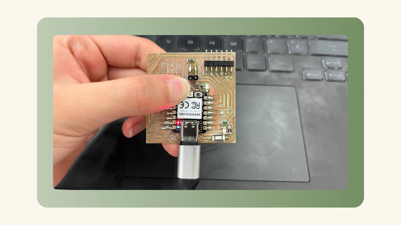
- I pressed the button labeled "B", then held it pressed while pressing the button labeled "R".
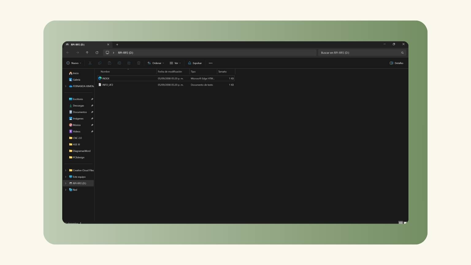
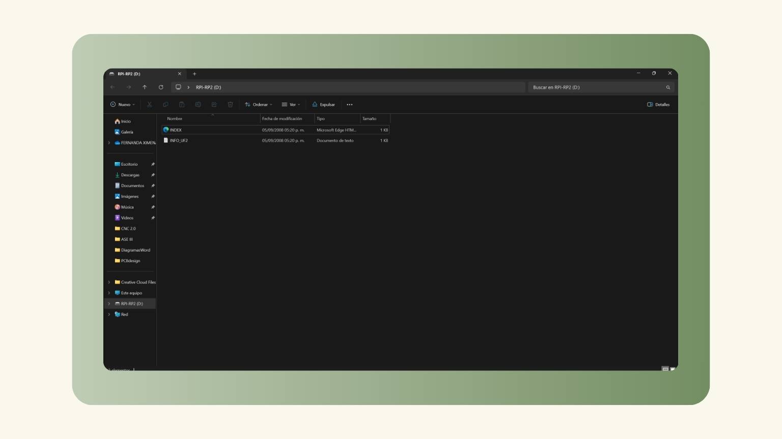
- I could then release both buttons, and the RP2040 would enter its reset mode. In that mode, it exposes its flash memory as a hard drive.
- Then, I added the uf2 file to reset, and the board looked like this:
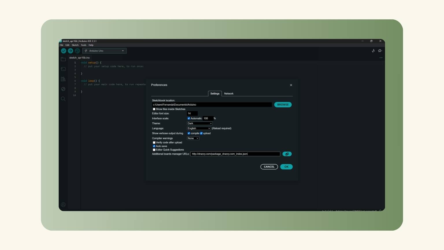
- I went to the ‘Arduino’ program and opened the 'Preferences' menu.
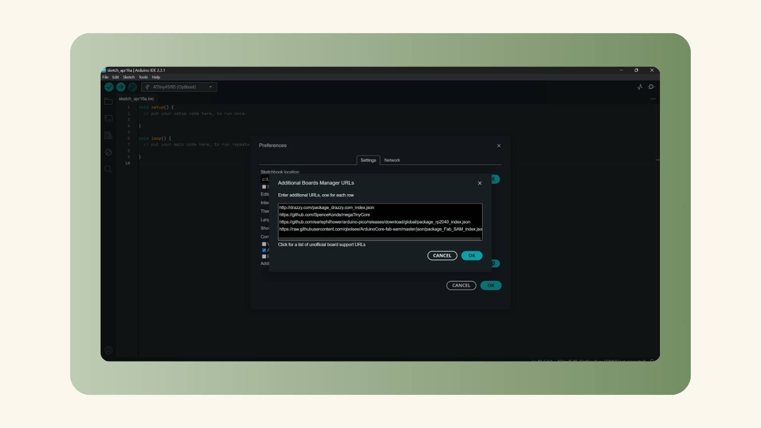
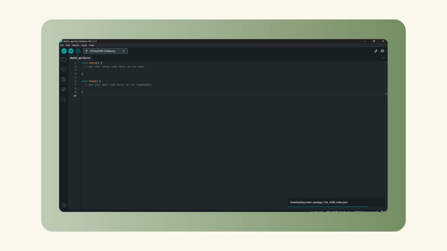
- I added the URLs that I needed.
- The libraries were downloaded.
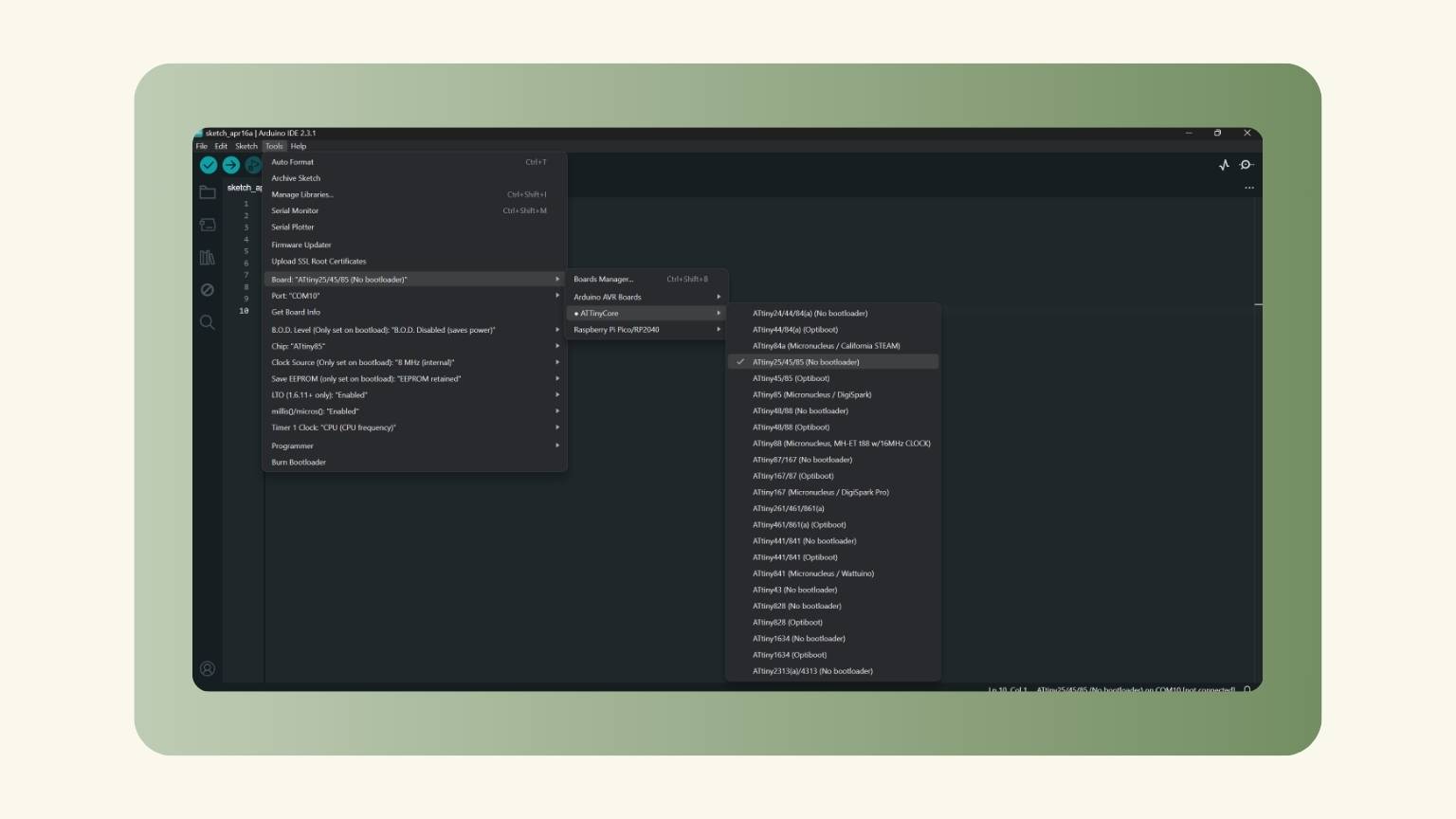
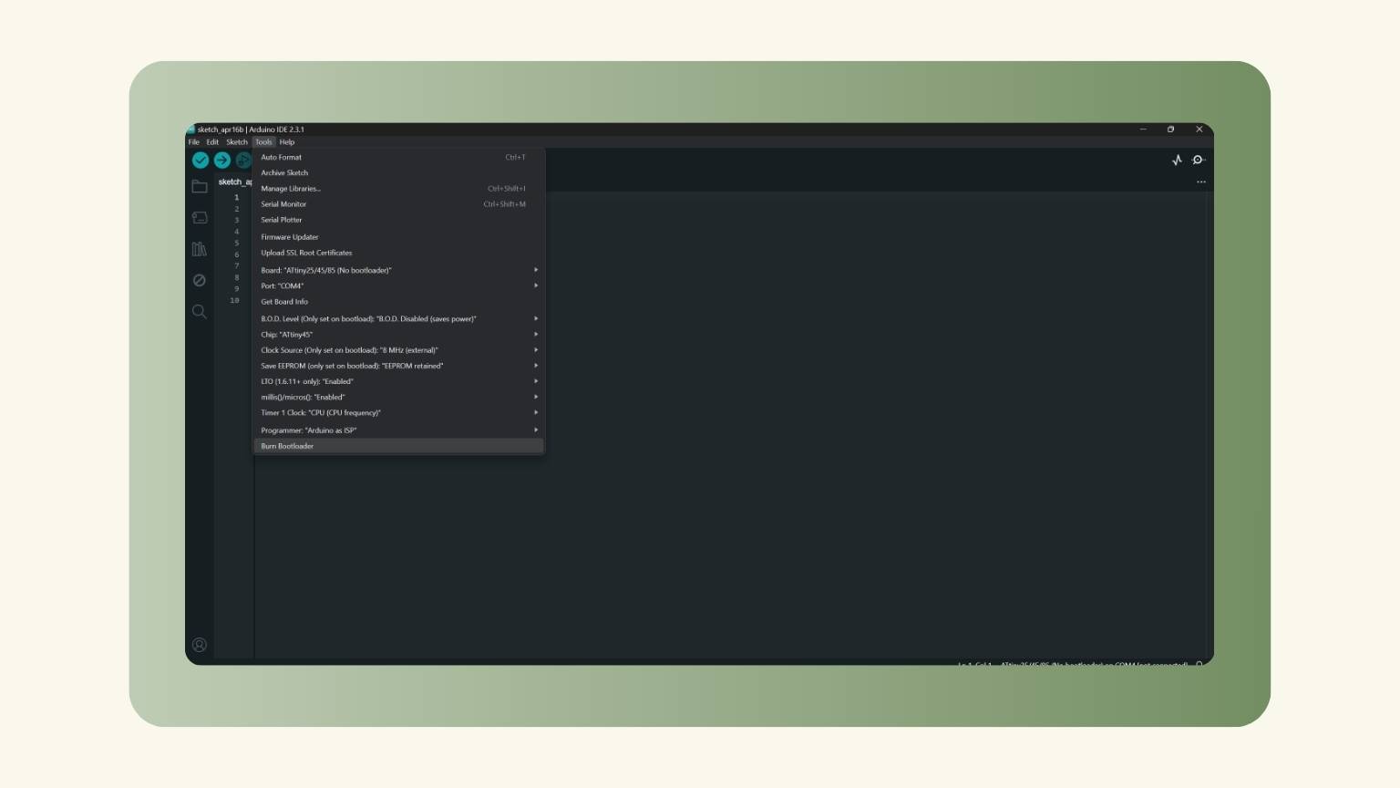
- I deployed the tools menu and selected Attiny 25/45/85 in the ATTinyCore section of the Board option.
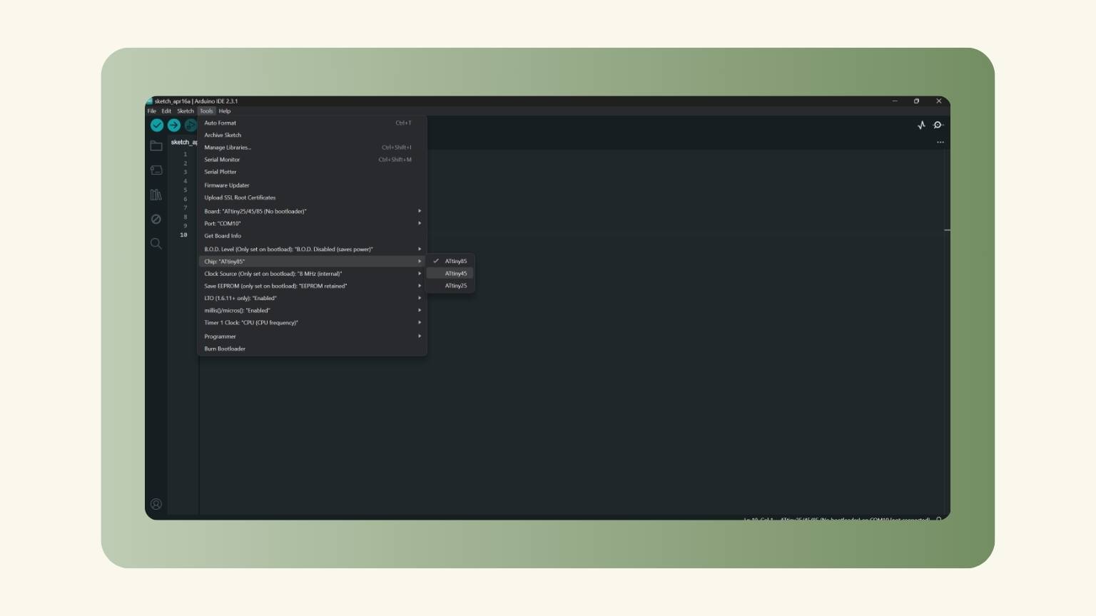
- I selected the specific chip that I used.
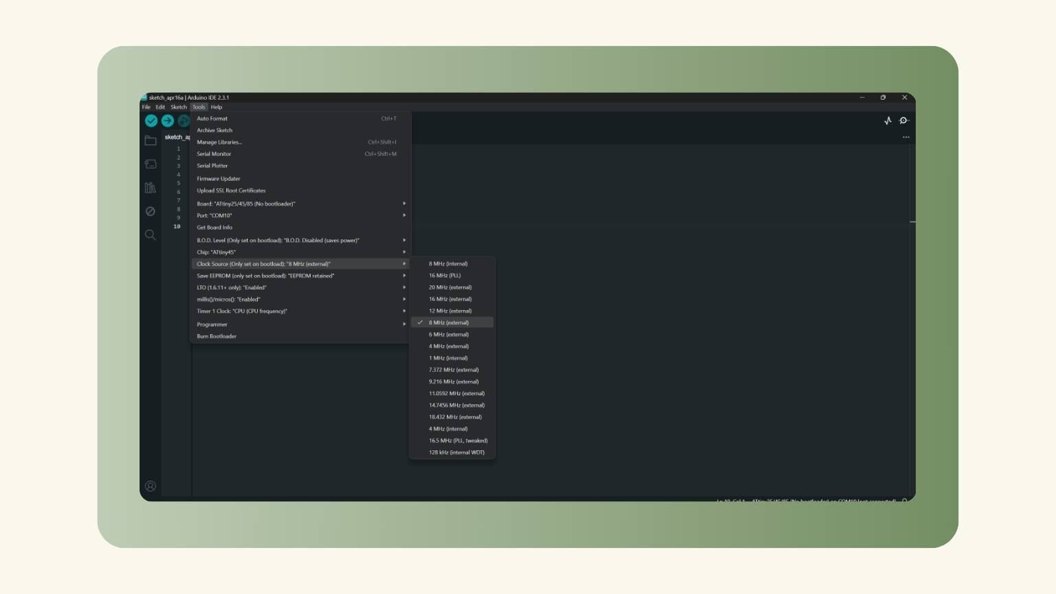
- I chose the clock source for the burn bootloader.
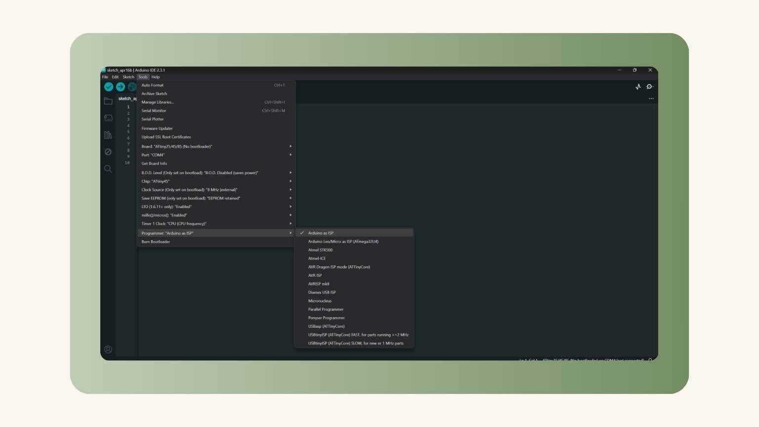
- I put the Arduino as ISP as programmer.
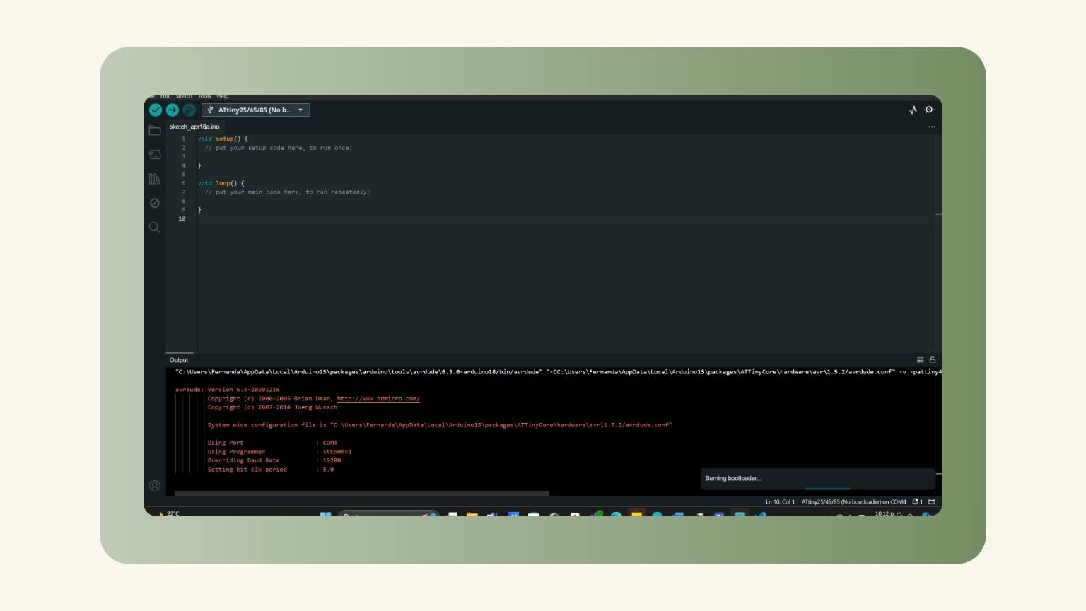
- I burned the bootloader.
- And I failed!
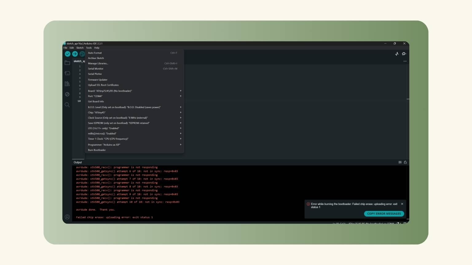
So...
I made a few adjustments here and there, but my botloader still didn't burn. I'll keep looking into what's going on to make the necessary corrections.
Conclusion
This is more difficult than one might think ...
... but I really hope I can make it!
Since I did not get the desired response from the proximity sensor...
I made another sensor!
A Light Sensor!
I didn’t make this adjustment in a vacuum. This sensor may help me with my final project, so I wanted to test its sensitivity and weigh its benefits and drawbacks before deciding whether to utilize it or pursue another alternative.
what is a light sensor?
Light sensors are photodetectors, also referred to as photosensors, that are designed to detect light. A variety of light sensors can be utilized for the detection of illuminance, the response to alterations in the quantity of light received, or the conversion of light to energy.
In essence, a photoelectric device transforms observed light energy (photons) into electrical energy (electrons).
There exist a multitude of types of photosensors, and in this instance, I employed a photoresistor to create mine.
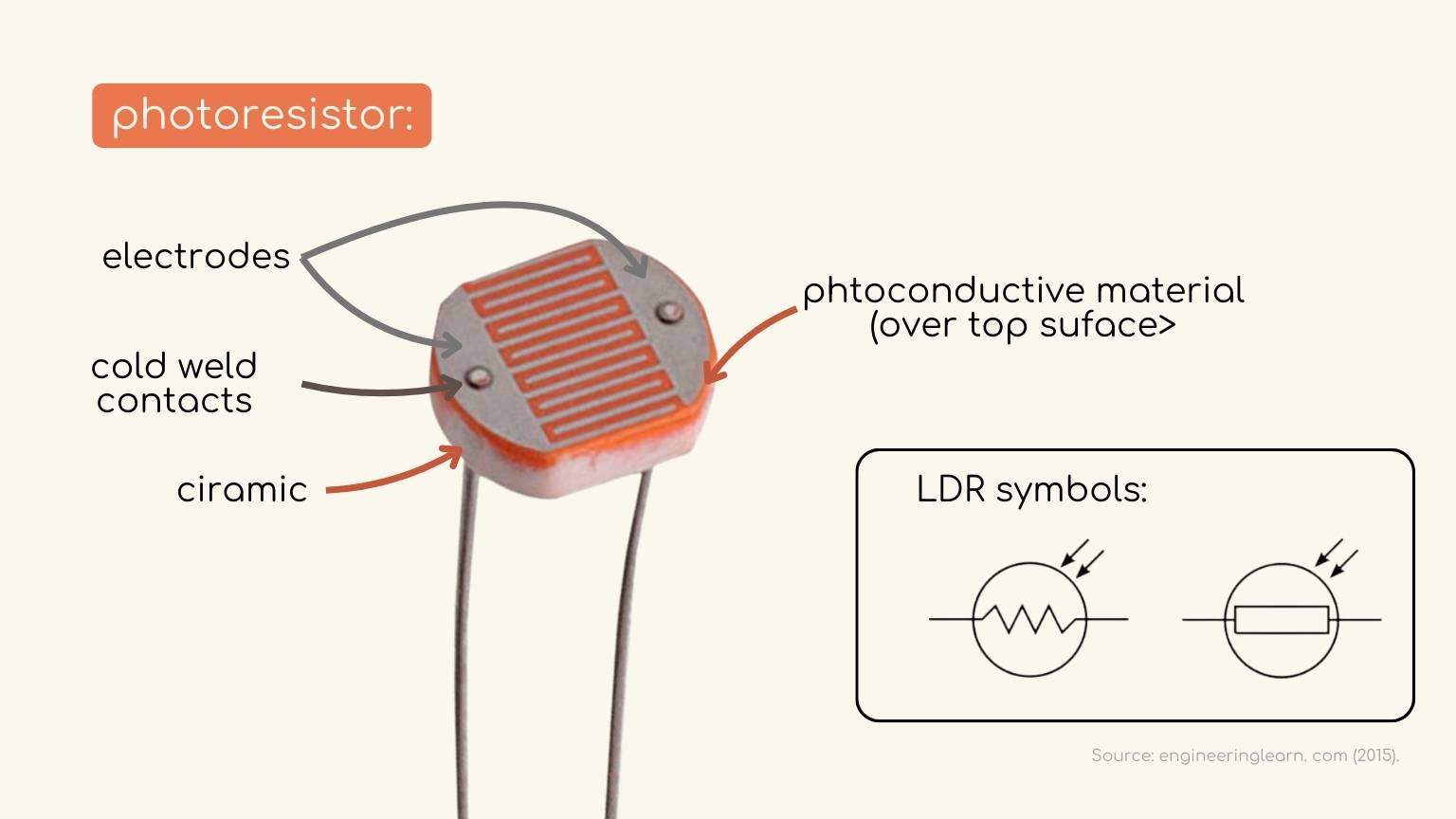
But… what is a photoresistor?
Photoresistors are light-sensitive resistors that exhibit a reduction in resistance as the light intensity increases.
I utilized the following schematic as a guide:
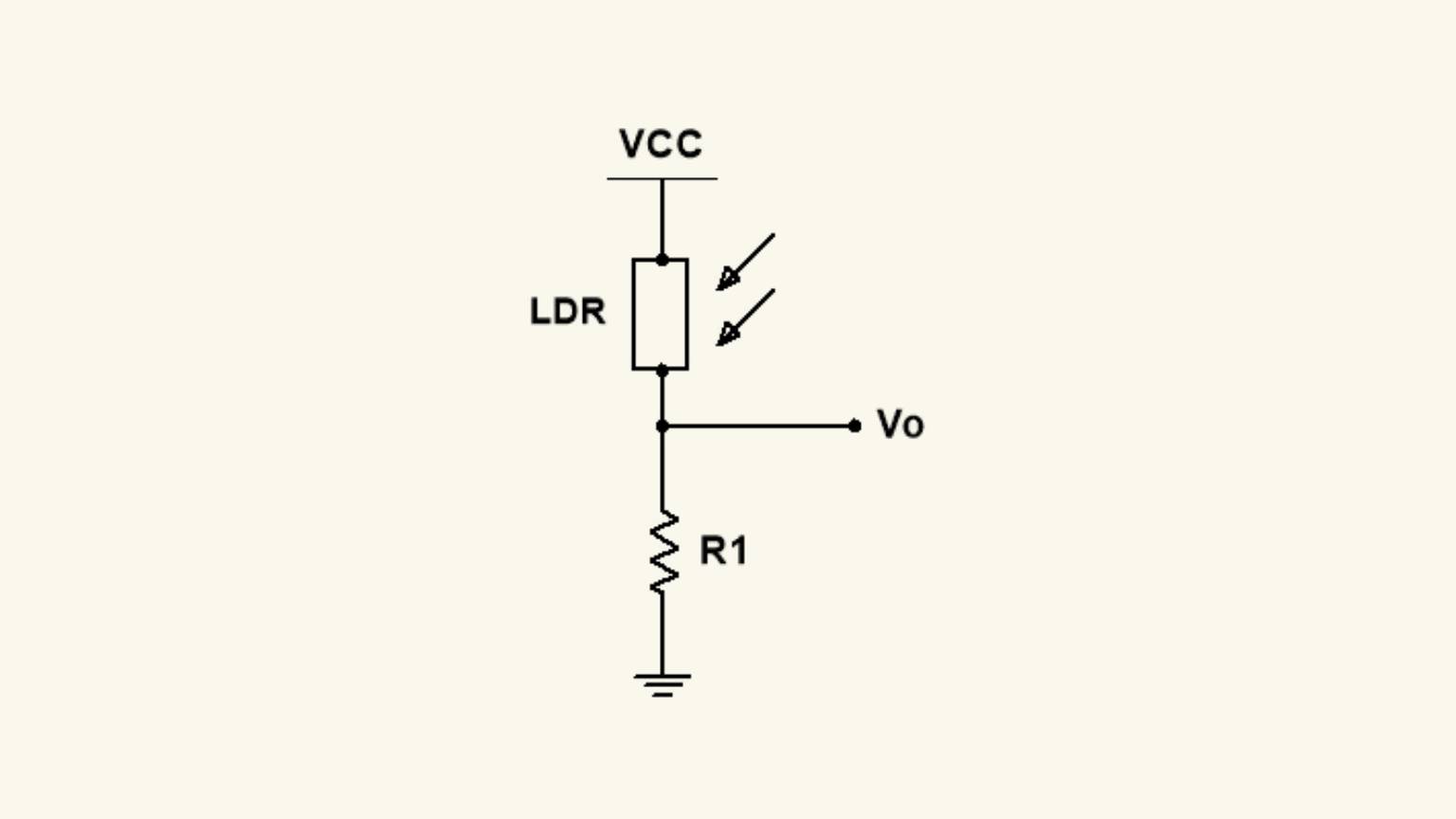
how did I do it?
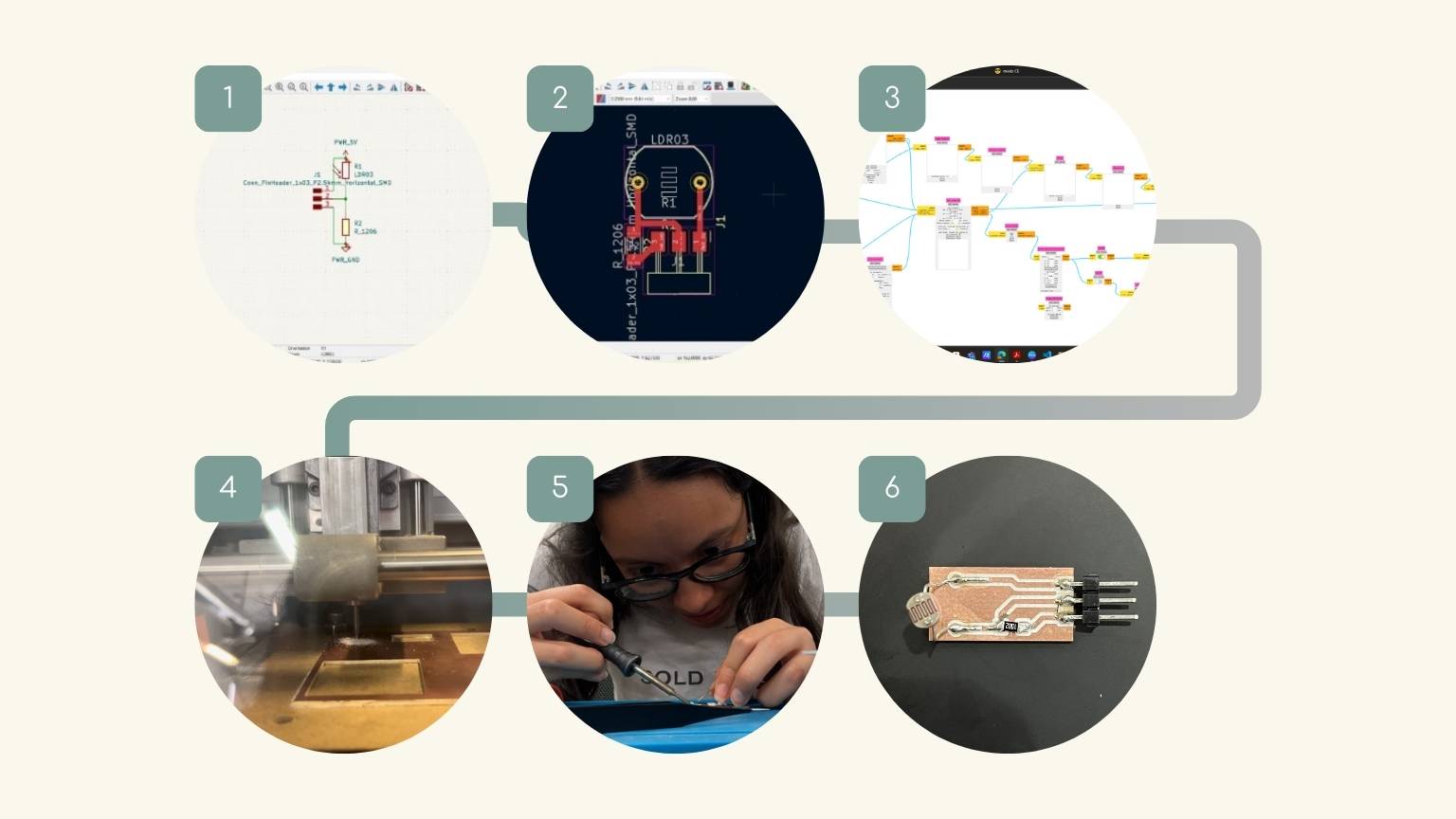
- The schematic was created in KiCad.
- I facilitated the requisite interconnections between the components in the PCB editor.
- The file was then subjected to modifications in order to facilitate the cutting process.
- The Roland was employed to cut the PCB.
- The necessary components were then soldered.
- The sensor was prepared for use.
Programming
In creating the program, I opted for a straightforward approach, whereby two LEDs would light up in response to a signal received by the phototransistor.
This was the code:
And its works!
The result:
Conclusion
The last sensor might have been badly built, but we'll never know for sure. However, I can state that developing a new sensor broadened my knowledge and gave me new possibilities for outputs. Perhaps I failed the first one...