7. Computer Controlled Machining
What is a CNC?
Computer controlled machining (CNC) is a manufacturing method that automates the creation of precise parts and components from materials such as metal, plastic, wood, and composites.
CNC machining is the process of translating a computer-aided design (CAD) model into a set of instructions, which are often expressed as G-code. These instructions govern the speed, location, and depth of cutting tools and workpieces on a CNC machine, ensuring excellent precision and reproducibility.
CNC machines are classified into several sorts, including milling machines, lathes, routers, laser cutters, and 3D printers. Each machine is designed for a certain task and material. CNC machining has various benefits over traditional manual machining processes, including quicker production speeds, greater precision, increased repeatability, and the ability to create complicated geometries with little human interaction.
Computer-controlled machining is critical in contemporary production processes in a variety of sectors, including aerospace, automotive, electronics, medicine, and consumer products.
Note: I will mention other important aspects later, but if you want to know more, check out the Fab Lab Puebla group page.
How I did this week?
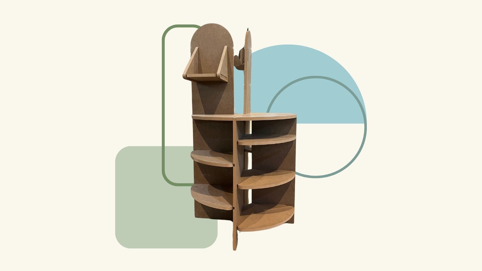
This week, I designed a versatile piece of furniture to organize items that no longer fit on my desk. It can be configured to suit different needs and types of objects that need to be stored.
Creating the design
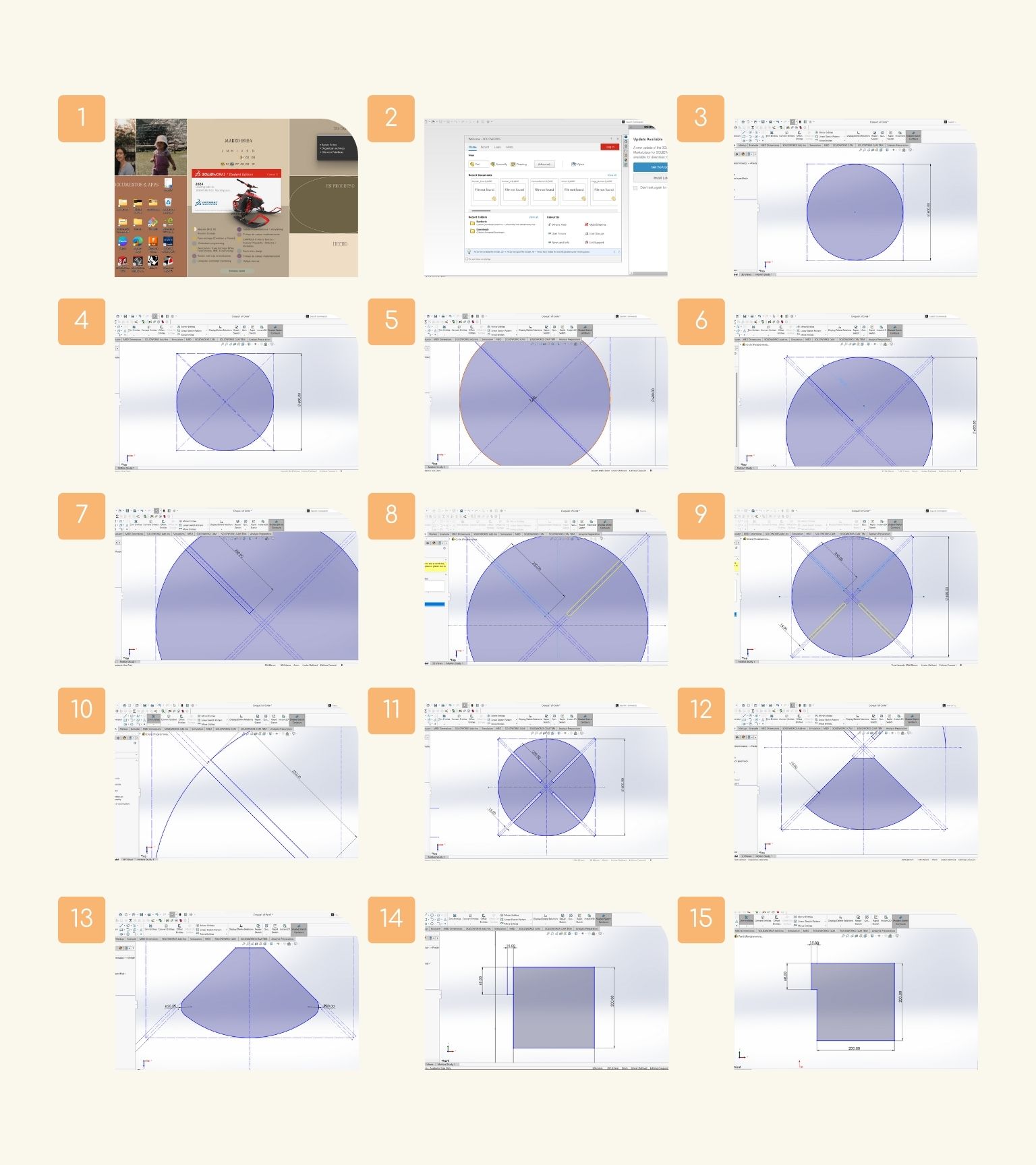
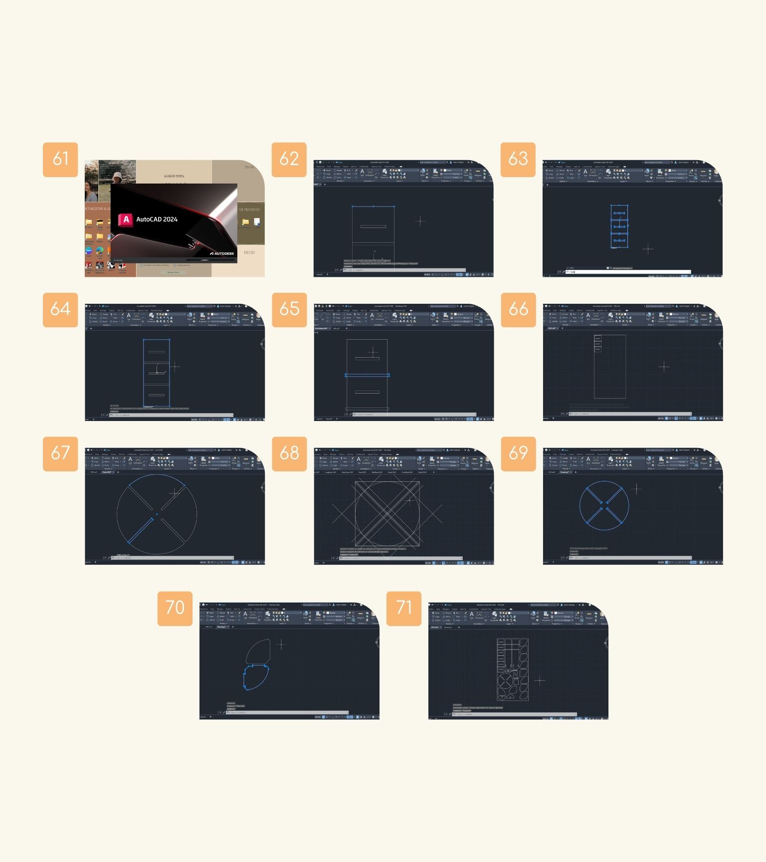
- First, I opened SolidWorks.
- Then, I created a new ‘Part’ for the first part of my object.
- I drew a square and an inscribed circle.
- I drew reference lines with the ‘Certerline’ tool.
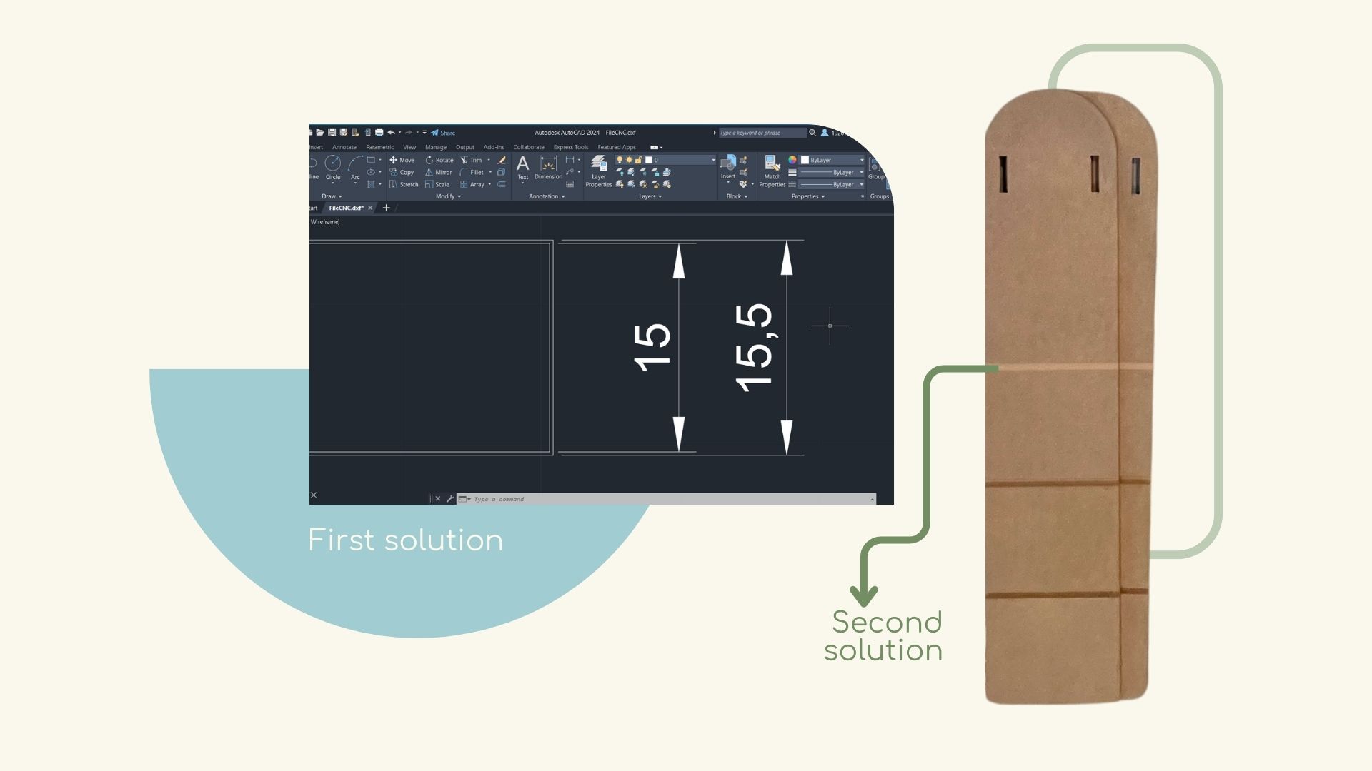
- With the ‘Offset’, I created other reference lines with a distance of 7.5 mm from those previously made.
- I used this distance because the total would be 15 mm, the thickness of the material to be cut.
- Then I traced a line with the ‘Line’ tool to calculate the distance you would make the hole for the part assembly.
- And I finished drawing the rectangle with the ‘Line’ tool to complete the shape.
- I used the ‘Mirror’ tool to reflect the shape on the other side to be sure they were of the same size.
- I did the same with the two lower forms.
- With the ‘Trim Entities’ tool, I deleted the strokes that were left over.
- I have my first piece!
- After, I used the traces of the first piece to make my second piece, because the part would be an element that would be assembled at the bottom and had to come out this way for it.
- Note: This part would be sliding, so consider only the extra 7.5 mm distance and not the 15 mm thickness of the material.
- I made a 30 mm fillet on the outside corners. And I have my second piece!
- From the third piece, I made a square of 200 mm, and in the upper right corner, I made a rectangle of 15 mm x 15 mm as the assembly tab.
- I deleted the internal traces of the shape to make a single piece.
- I didn't want it to remain a simple square, so I drew a diagonal line to transform it into an isosceles triangle.
- Note: When I made a fillet in the lower right corner, the length of the figure changed, and I wanted this one to be 200 mm. So, in the corner, I made a circle with a 30 mm diameter at 20 mm. To do this, I used different reference lines.
- Then, I deleted the strokes that were left over to close the shape. And I created a hole for the part assembly. So, I have my third piece!
- Next, I made a rectangle of 185 mm x 200 mm, and then I made a reference line to 20 mm from the lower edge and another to 15 mm (the thickness of the material) from the left lateral edge.
- I made a line to create the assembly part of the piece.
- I deleted the strokes that were left over to close the shape.
- And I have my fourth piece!
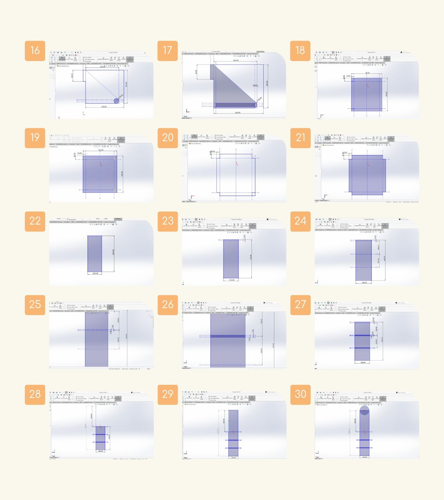
- I made another rectangle measuring 250 mm by 640 mm.
- I created a reference line at 15 mm from the upper edge.
- Then, I made another at 28 mm.
- In the second's reference lines, I made another’s reference lines at 7.5 mm up and down.
- Next, I made a rectangle of 250 mm by 15 mm; this would be the part where certain parts would slide.
- And I have my fifth piece!
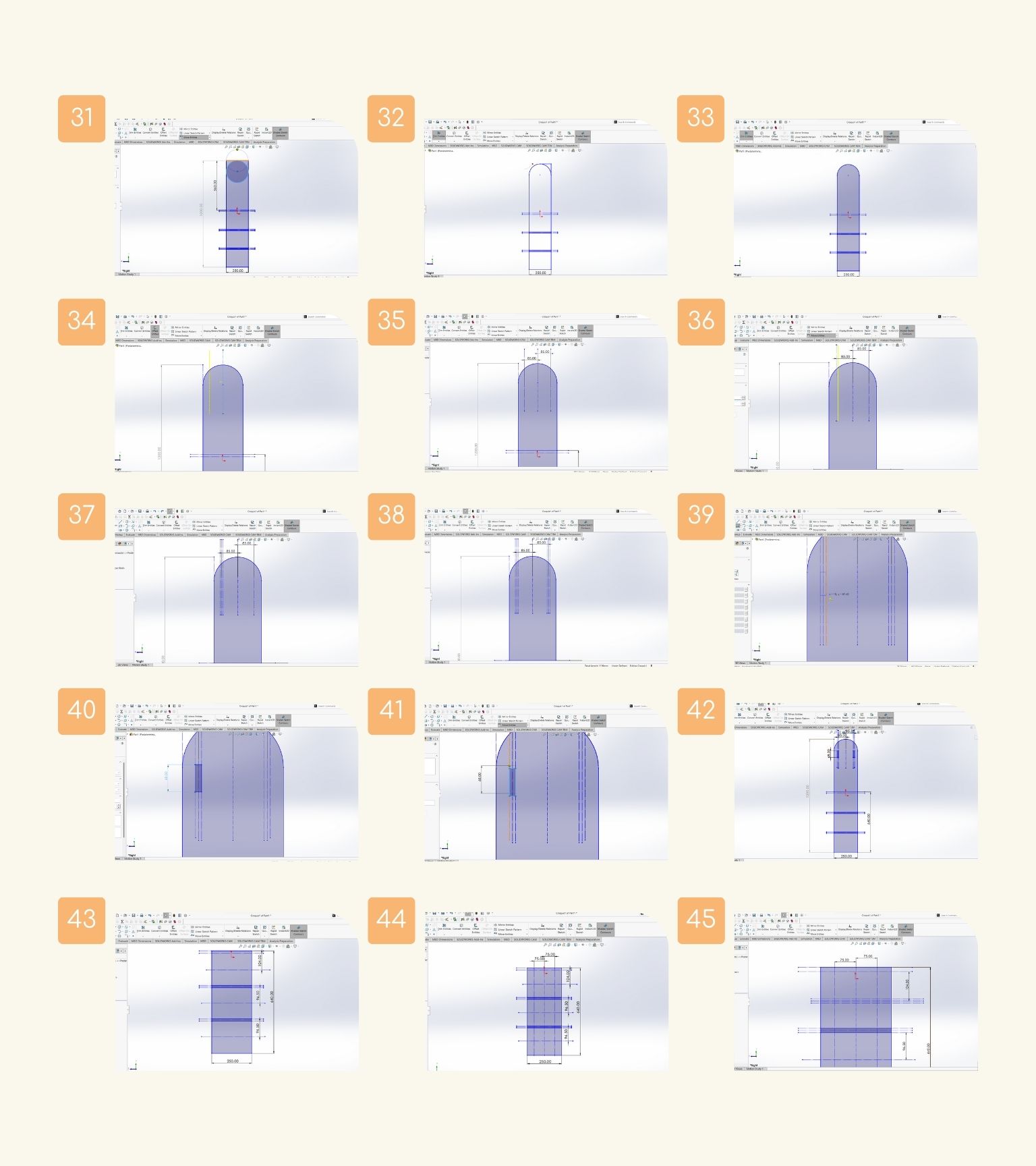
- I used the strokes from the fifth piece for the following piece. So, I wanted a piece with a height of 1200 mm, and for this, I drew a 560 mm reference line.
- Based on the reference line, I drew a rectangle to complete the height.
- After, I made a circle 250 mm in diameter.
- I moved the circle to maintain the height of 1200 mm.
- I deleted the strokes that were left over to close the shape and create one piece.
- Then, I made a reference line in the center of the shape and another at 85 mm.
- And the same on the other side.
- I created other lines at 7.5 mm to make the following figure.
- It was as follows in the image.
- Later, I mirrored the same on the other side.
- I created a rectangle.
- I modified the height of the rectangle to 68 mm.
- When I modified the height, I changed the position of the shape. And I moved it to the right position.
- And I have my sixth piece!
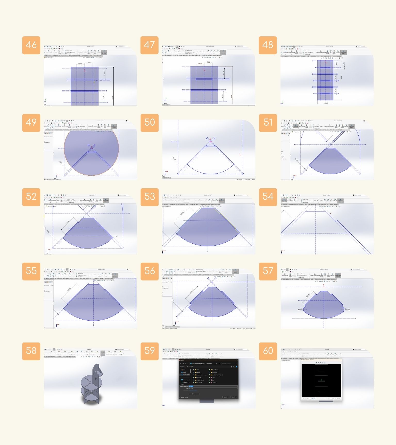
- I decided to add other assemblies to my object, so in the fifth piece, I made some modifications. First, I created three different reference lines, one at 104 mm and the other two at 96 mm, from the centerline of the holes already made.
- Then, I created another’s reference lines, one in the middle and two 75 mm on both sides.
- I made two reference lines at 7.5 mm on both sides of the line already created.
- I created a rectangle for the new hole.
- And I have a new hole.
- I did the same in the other section of the shape. And I have my seventh piece!
- To make these new holes, I made another piece considering the strokes of the first circular piece. And use the third line for the shape, which considers the 15 mm thickness of the material.
- I deleted the strokes I wouldn't need.
- I have a closed piece.
- Then, in the middle of the lateral lines, I made the assembly shape, which was a rectangle of 150 mm by 15 mm, and I deleted the excess strokes.
- I made a mirror of the assembly on the other slide.
- I deleted the excess strokes.
- And I realized that I was only considering that it would be assembled at half the thickness of the other piece.
- So, I corrected it.
- And I have my final piece!
- I extruded all the pieces.
- After, I assembled all the pieces to make sure that everything was correct.
- I saved all the plan views of the parts in ‘dxf’ format.
- Finally, the preview is displayed to confirm what you want to save, and then click on ‘Save’.
- Next, I opened ‘AutoCAD’ to verify that all the lines of the parts' strokes were joined and to put in the same document.
- So, I opened one piece, and I saw that the strokes were separated.
- I selected all the shapes, and I used the ‘Join’ command to make the lines a single stroke.
- I verified that the join was made.
- I checked all the figures.
- Then, I copied the piece, and I placed it in a new document, inside a rectangle with the measurements of the material.
- When I joined the circle piece, it was not possible because some of the curves did not reach the next point to close them.
- So, I made all the drawings again.
- With the ‘Trim’ command, I deleted the strokes that weren’t necessary.
- I did the same with the other two pieces that had curves.
- And I continued to arrange all the pieces within the limits of the material until I had all of them.
AutoCAD
What happens next once I have the design?
VCarve
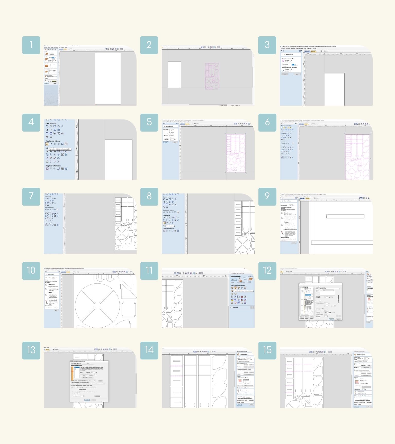
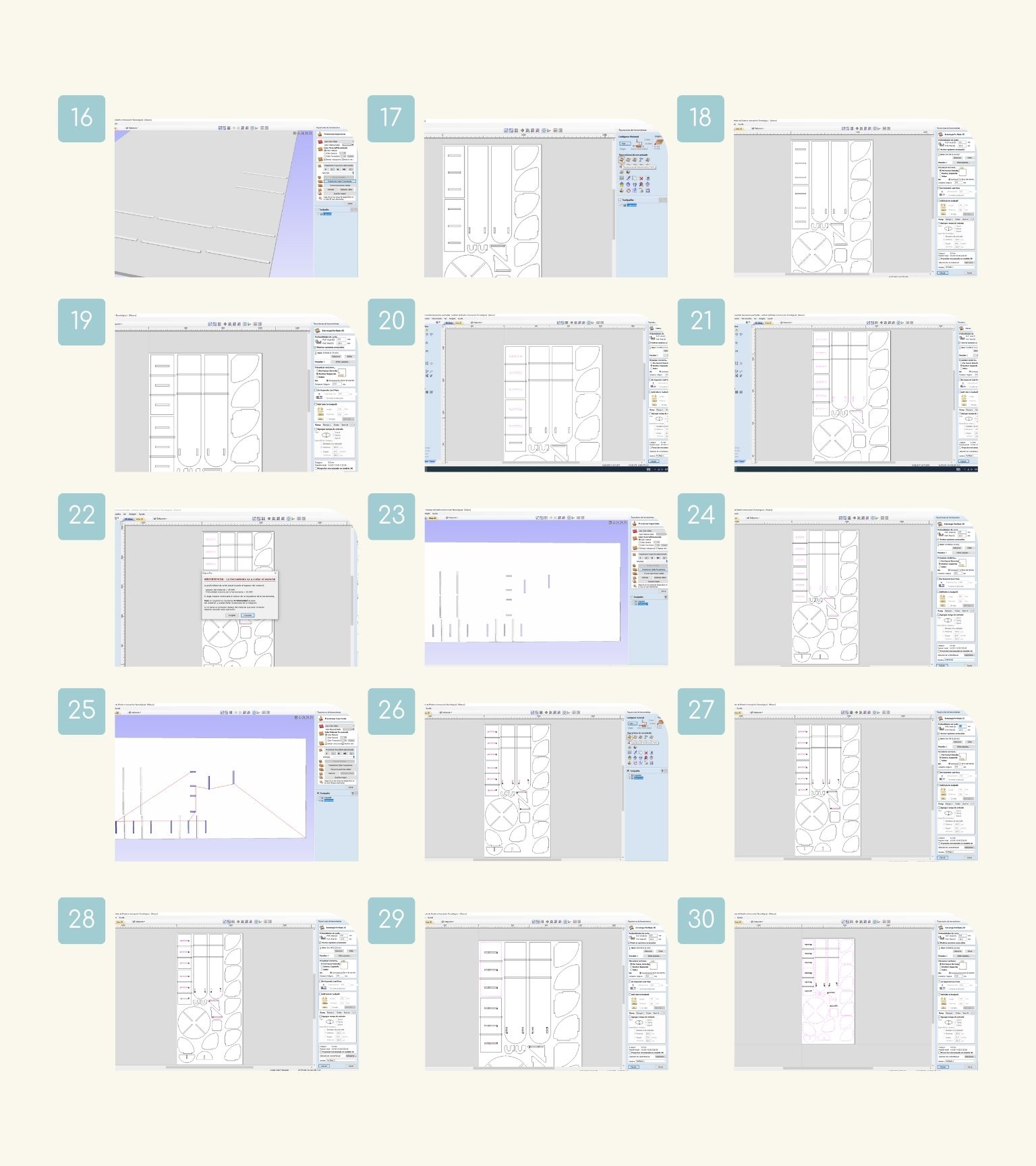
- First, I put the measurement of the material, in this case, 1220 mm of width, 2440 mm of height, and a thickness of 15 mm.
- Then, I opened the file for my object.
- I checked that all the pieces were closed with the ‘Join the open vectores’ tool.
- I moved the pieces to the workspace with the ‘Move’ tool.
- In the menu of the tool, I selected the lower left tip as the anchor point. And on the x and y axes, I placed 0 mm.
- And all parts were moved to the workspace.
- I unselected the pieces for the next step.
- Next, I used the ‘Create chamfers’ tool to create the ‘Dog Bones’ for a great assembly.
- I created it in the holes where an object would fit.
- Next, I added chamfers to the corners of the piece to fit.
- After, I made my first mechanized operation: Pocketing.
- To start, I selected the tool with which I would carry out the roughing and verified that all the data on the toll was correct.
- Then, I modified the number of passes the tool would make to perform the operation.
- Note: You delimited the passes with the depth of the tool, which should be at least half of the tool diameter.
- I selected the shapes required for the operation.
- When all the shapes were selected, I pressed ‘Calculate’.
- I saw a previsualization of the operation to see that everything was okay.
- Next, I made the second mechanized operation: Profile.
- I defined the final depth at 15.3 mm.
- Note: I chose this measurement to make sure that the operation was performed.
- I corroborated that the selected tool was the same and that the number of passes was correct.
- I selected the interior pieces for this operation.
- When I selected all the shapes, I changed where the tool would pass through to perform the operation, changing it towards ‘Inside / Left’.
- When I clicked ‘Calculate’, an ad came up stating that the depth of the operation is greater than the thickness of the material, but as I said before, that was done intentionally to ensure the cut, taking into account that there is a sacrificial table underneath the material.
- I saw the previsualization of the operation.
- I changed the name of the operation to have a more detailed description of the mechanized.
- And I could see the route that the tool would follow when cutting.
- Finally, I made the last mechanized operation: Profile.
- So, I verified that the final depth was 15.3 mm, and that the tool was correct.
- I changed where the tool would pass through to perform the operation, changing it towards ‘Outside / Right’.
- I started to select the shapes to which this operation would be applied.
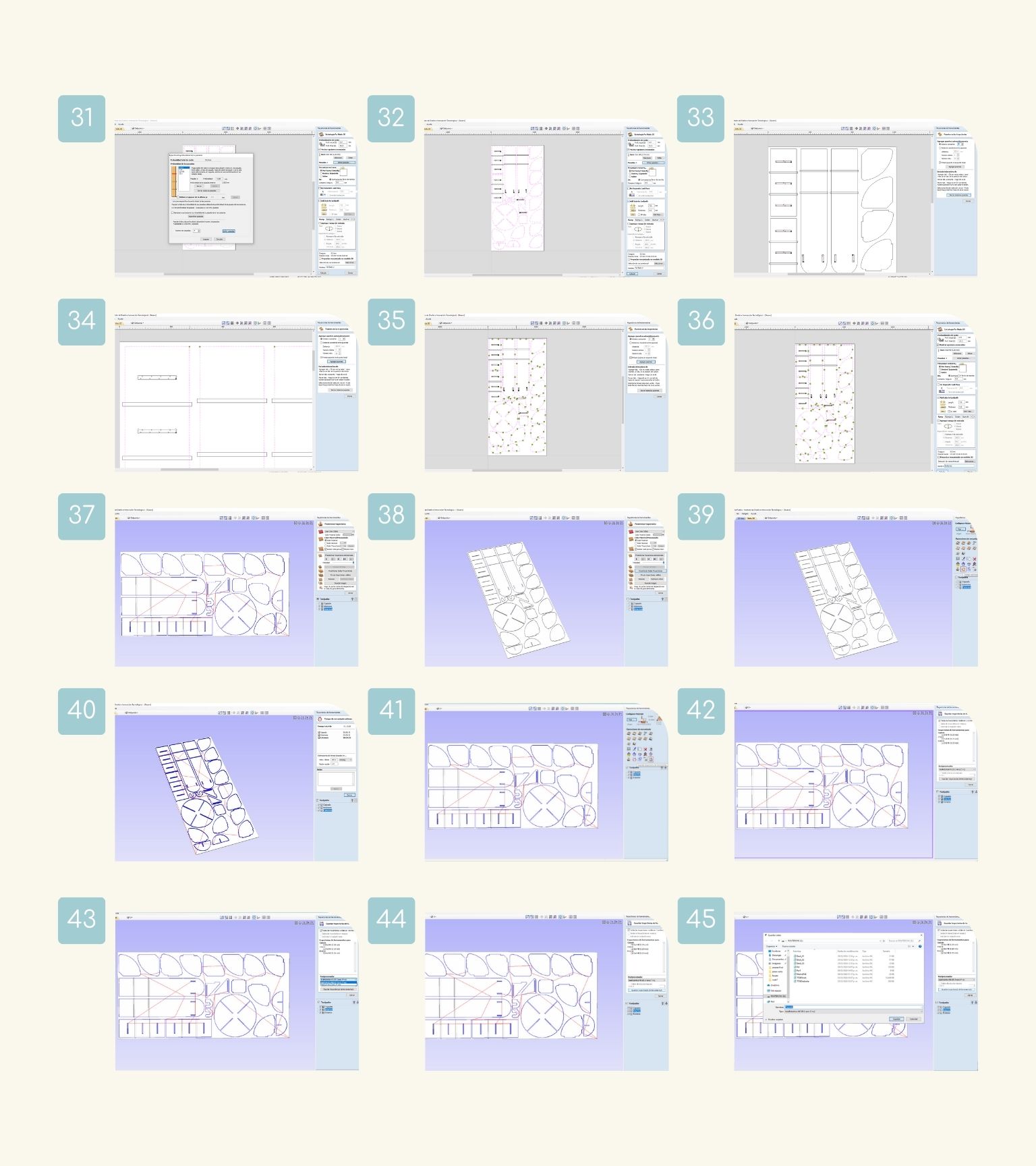
- I selected all the part outlines.
- Then, I changed the number of passes to optimize.
- I active the section of ‘Add tabs to toolpath’i>. This was necessary to make sure that the parts do not move during the operation and, in the worst case, do not fly away.
- I added an automatic number of tabs, in this case, three for each piece.
- I pressed ‘Add tabs to see where these tabs would be.
- I made some changes to the location and number of tabs for each piece.
- When I had the tads, I pressed ‘Calculate’.
- I saw the previsualization and the route of the tool for the operation.
- Then, I saw the previsualization of all the operations realized.
- I checked the estimated time it would take to perform all operations in the ‘ Estimated machining time’ option in the menu of tools ‘Toolpaths’.
- The estimated time was 54 minutes.
- Then, I saved the file in the ‘ Save toolpath’ option.
- I verified that all the operations were selected.
- In the postprocessor, I selected ‘AsiaRobotics-NK105.3.arcs(‘.nc)’.
- I pressed ‘Save toolpath’.
- I saved the file on a USB to send it to the machine later.
How do I use the machine?
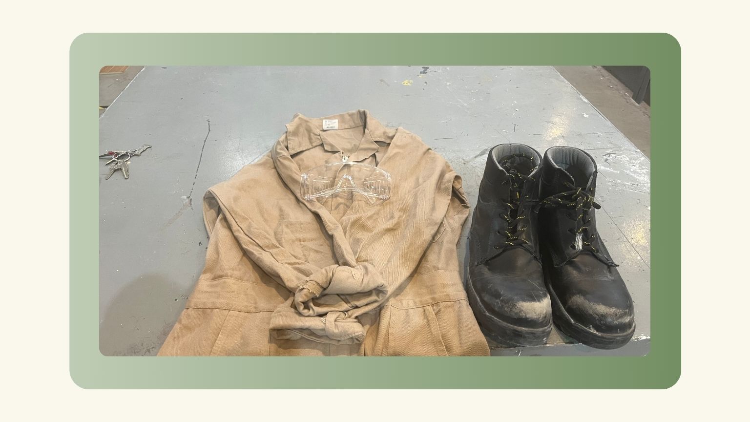
Important: Before using the machine remember to have your safety equipment.
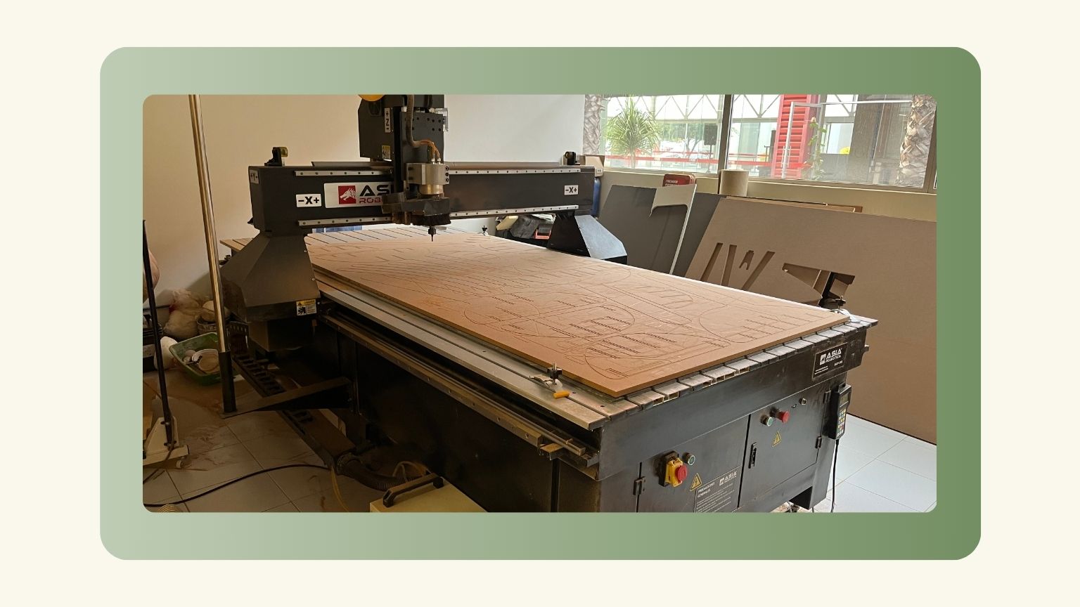
ASIA Robotica shop-1325
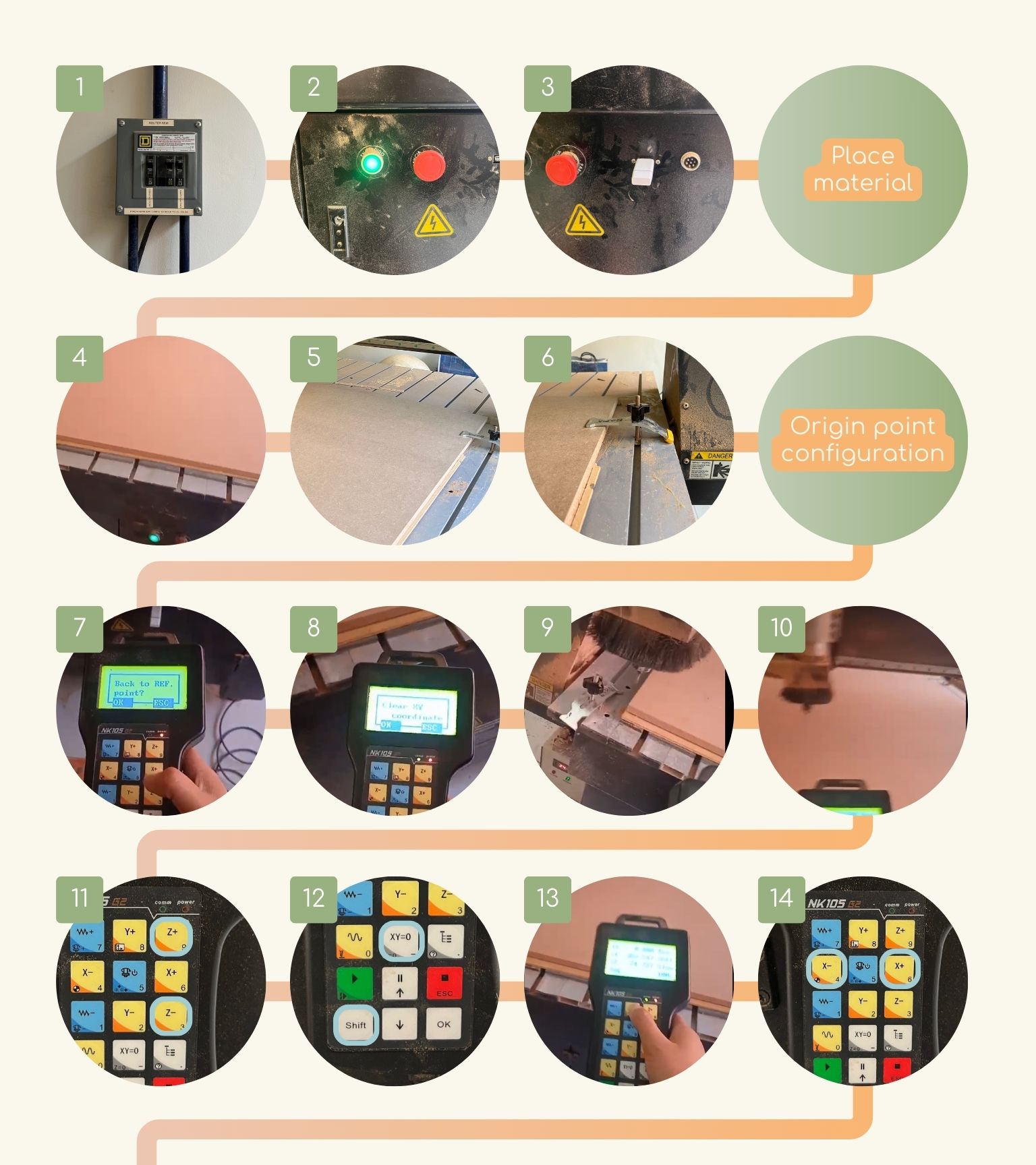
- Turn on the ASIA switches.
- Turn on the switch located at the front of the machine, specifically on the upper right side. It’s the green button.
- I plugged the USB into the input located on the right side of the emergency stop.
- Note: The "G" code file should already have been loaded on a USB flash drive to be inserted directly into the machine. Continue with the following steps:
- I put the material on the machine bed.
- I aligned the material with respect to the machine bed.
- I attached the material to the workbench.
- To do this, I used clams, which are inserted into the guide, and then ensured that one yellow leg was placed on the material and the other on the table, then secured it with the black knob.
- Note: It is necessary to secure at least two clams.
- When you turn on the machine, an announcement will appear on the machine control saying if you want to go to the reference point, and I press ‘OK’.
- I cleaned the XY coordinates to reconfigure them.
- First, I moved the z-axis upward.
- When it was high enough, I moved the ‘x’ and ‘y’ axes so that the position would be in the center of the workspace.
- Then, I set the position of ‘z’ using buttons 3 and 9.
- Once I had the position delimited, I saved the position as the point of origin by pressing Shift and the ‘XY=0’ button.
- After that I configured the ‘x’ and ‘y’ positions.
- To do this, you control the axis with the machine control.
- I used buttons 4 and 6 to control the ‘x’ position.
- Note: If you want a slower or faster movement, you must press Shift to regulate the speed of the movement.
- Next, I used buttons 2 and 8 to control the ‘y’ position.
- Once the x and y positions were known, I saved them as the point of origin with the ‘XY=0’ button.
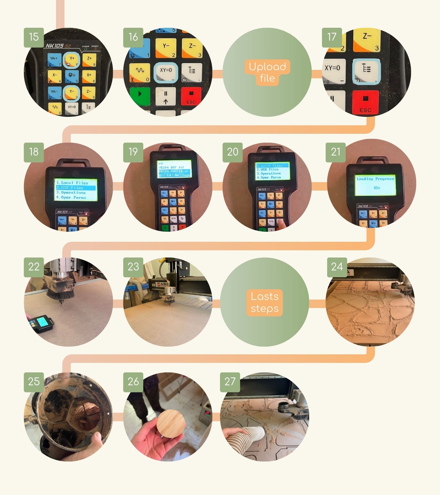
- I went back to the control menu, pressing the button with a diagram.
- I selected the ‘USB Files’ option to find my file.
- I searched for my file, and once I found it, I copied it to local memory.
- I went back to the main menu and now selected the ‘Local Files’ option.
- And browse for the file you copied; once I found it, I selected it with OK.
- Then, I moved the coordinates of ‘x’, ‘y’ ,and ‘z’ to the middle of the workplace.
- Finally, I started the cut.
- The cut was already.
- I couldn’t go vacuuming because the sawdust extractor was clogged.
- I uncovered the sawdust extractor; It had a solid piece of sawdust stuck in it.
Place material
Origin point configuration
Upload file
Result
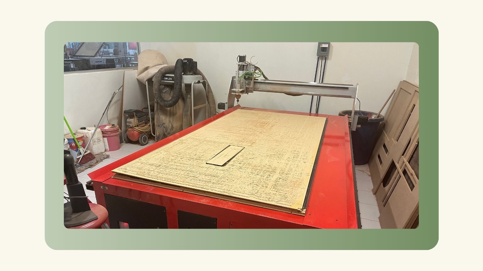
Generic made by the university
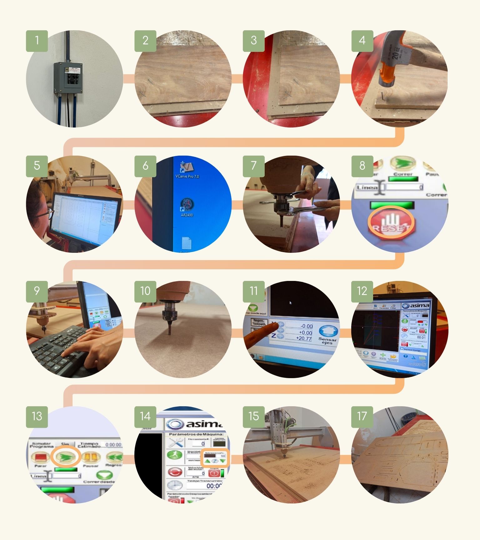
- Turn on the switch located at the front of the machine, specifically on the lower left side. It’s the red button.
- I put the material on the machine bed.
- I aligned the material with respect to the machine bed.
- I attached the material to the workbench.
- To do this, I used nails, which were placed in the corners of the material, considering that the cuts would not be made in these areas. And with the help of a hammer, the material was nailed to the workbench.
- Note: The nails should only reach the sacrificial bed.
- Then, the file could be configured in VCarve from the machine's computer in case you want to follow the steps in the VCarve section.
- Once I had the file, I opened the software ‘asima’.
- I positioned the tool and made sure it wasn’t loose.
- I pressed the ‘RESET’ option located on the lower left side.
- To establish the coordinates of the axes ‘x’, 'y', and ‘z’. I used the next commands:
- So, I established the coordinates of the ‘Z’ axes in the center of the workspace.
- Note: This is the recommendation to be sure that the cut is made through the entire thickness of the material.
- Then, I established the coordinates of the ‘X’ and ‘Y’ axes, and I saved them by clicking on the ‘+’ next to the letter of the axes.
- I opened the file in the software.
- When the coordinates were saved, I pressed the ‘Play’ button.
- In the section on ‘Overadvance’, I changed the percentage to 50% to ensure that the cutting is being performed correctly. After I changed to 100%.
- And the cut started!
- Once the machine finished machining, I moved the tool up and back to safely remove the material that was used.
- Before removing the material, I vacuumed up the wood dust generated by the cut.
Place material
File configuration
Origin point configuration
| Command | Description | |
| CMD + Re Pág | Used to quickly move the ‘Z’ axis upward. | |
| Re Pág | Used to move the ‘Z’ axis slowly. | |
| CMD + Av Pág | It is used to quickly move the ‘Z’ axis downward. | |
| Av Pág | Used to slowly move the ‘Z’ axis downward. | |
| CMD + ⬆ | Used to quickly move the ‘Y’ axis towards. | |
| ⬆ | Used to move the ‘Y’ axis slowly towards. | |
| CMD + ⬇ | Used to quickly move the ‘Y’ axis forwards. | |
| ⬇ | Used to move the a ‘Y’ xis slowly forwards. | |
| CMD + ⮕ | Used to move the ‘X’ axis quickly to the right. | ⮕ | Used to move the ‘X’ axis slowly to the right. |
| CMD + ⬅ | Used to move the ‘X’ axis quickly to the left. | |
| ⬅ | Used to move the ‘X’ axis slowly to the left. |
Note: If you want to know more, check out the Fab Lab Puebla group page.
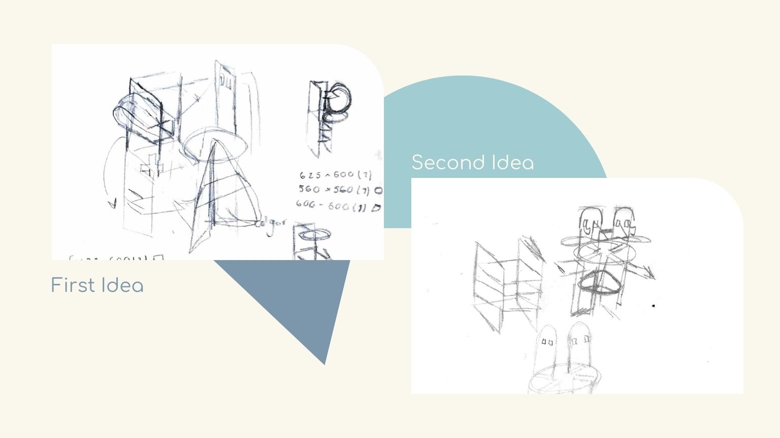
The problems…
The truth is that this week it wasn’t a piece of cake... So here are some of the things that happened to me, and even some tips that may be useful to you.
Calculate the dimensions of your material and be sure that all the pieces are kept in the area, because first I have a design that I must change because I didn’t consider the dimensions of the material.
Trust your instincts! From the beginning, I was not convinced that I didn't need to calculate a kerf. So, I didn't calculate it; I cut my parts, and the problems came:
- The assemblies did not fit together as smoothly as desired… And maybe you think that this wasn’t a mistake, but for me it was, because my object was designed to be modular and to have different configurations… So, yes, it was a nightmare. To solve it, I did different things:
- First, make the assembly spaces of some pieces, considering a tolerance of 0.25 of offset.
- Second, make a pocket in the area where the other piece would fit in. The pocketing that I made was 0.2 mm.
- Here I would also like to emphasize that, if paint is applied, it will still have a thickness that should be considered since it will thicken the material a little and therefore will not be able to match with another piece.
If you do pocketing, you must analyze your purpose. I say that because, in my case, I made a pocket to try another type of assembly and configuration.
- This assembly consists of roughening half of the material thickness to insert one piece in this space and hold it at 7.5 mm. But it was a pocket, and in the configuration of VCarve, it doesn’t have a profile to put if you want the tool to make the operation inside, outside, or under the vector. So, in this case, there are two options:
- First, calculate the tolerance, and when making the drawing of the piece, consider this dimension.
- Second, calculate the tolerance, and in the section of ‘ Pocketing’ put this measurement in the ‘Pocketing Tolerance’ option.
The design can be improved… I say this mostly because there are certain things that don't work quite right in the design.
- One of these aspects has to do with the circular piece; the holes for the assembly are very close to reaching the center of the same figure, which is not recommended as it is likely to break when forcing the assembly too much.
- Another would be that we need a piece at the base that can ensure that the vertical pieces are at the correct angle for the assembly of other pieces and to keep the object in the correct position.
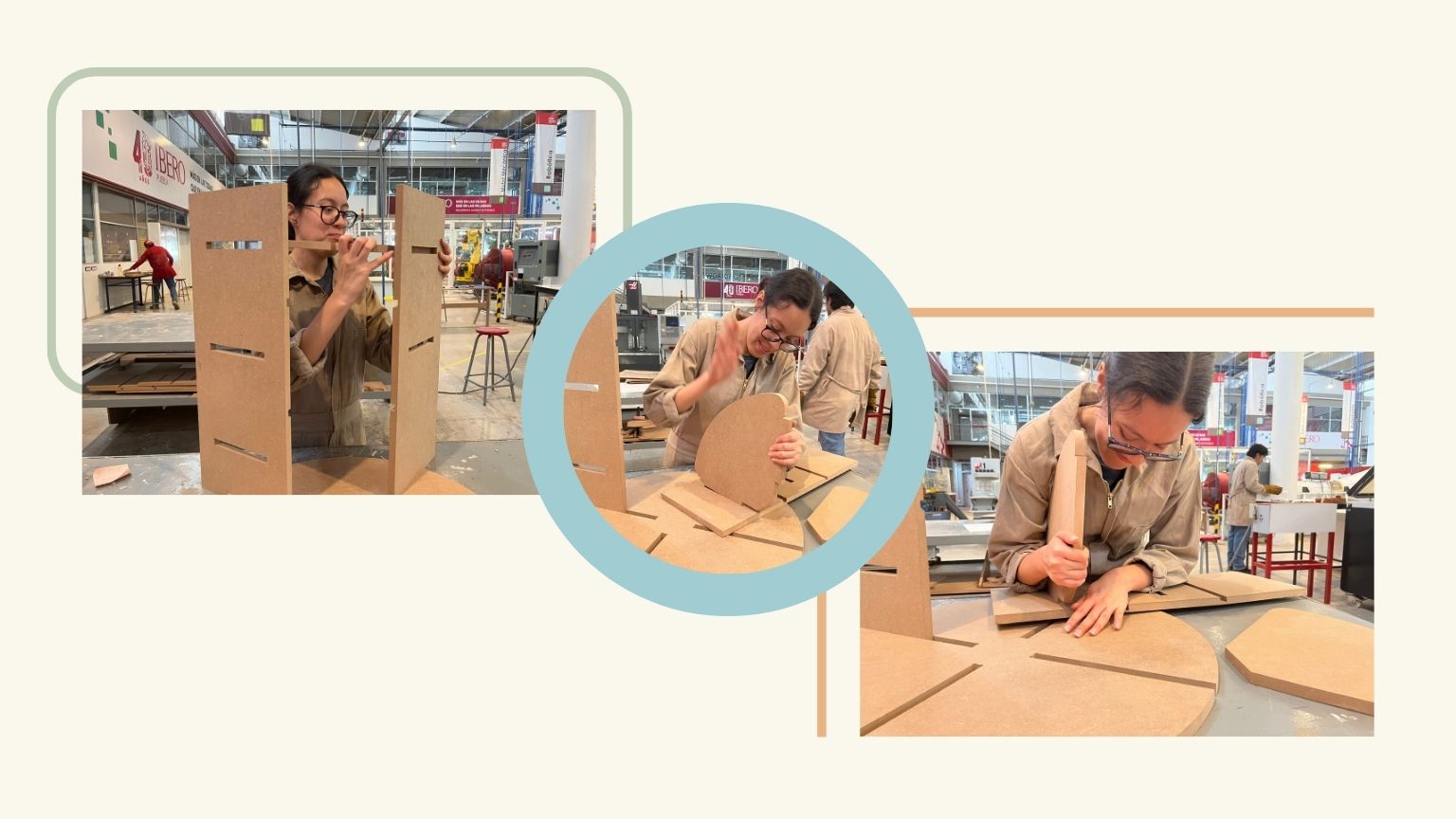
- And finally, angled assemblies. I only had complications with the first one (see the image) because I could not fit it once the vertical pieces were already in their respective places, so I had to first fit them together and then all of them with the circular piece.
- So, I would do more tests to solve this problem.
The good news is that I learned new things from my mistakes!
Assembly
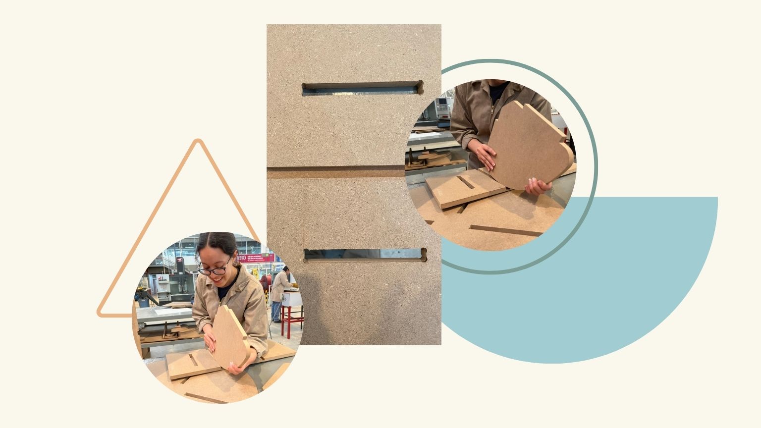
Once I had the parts ready, I began to assemble my object.
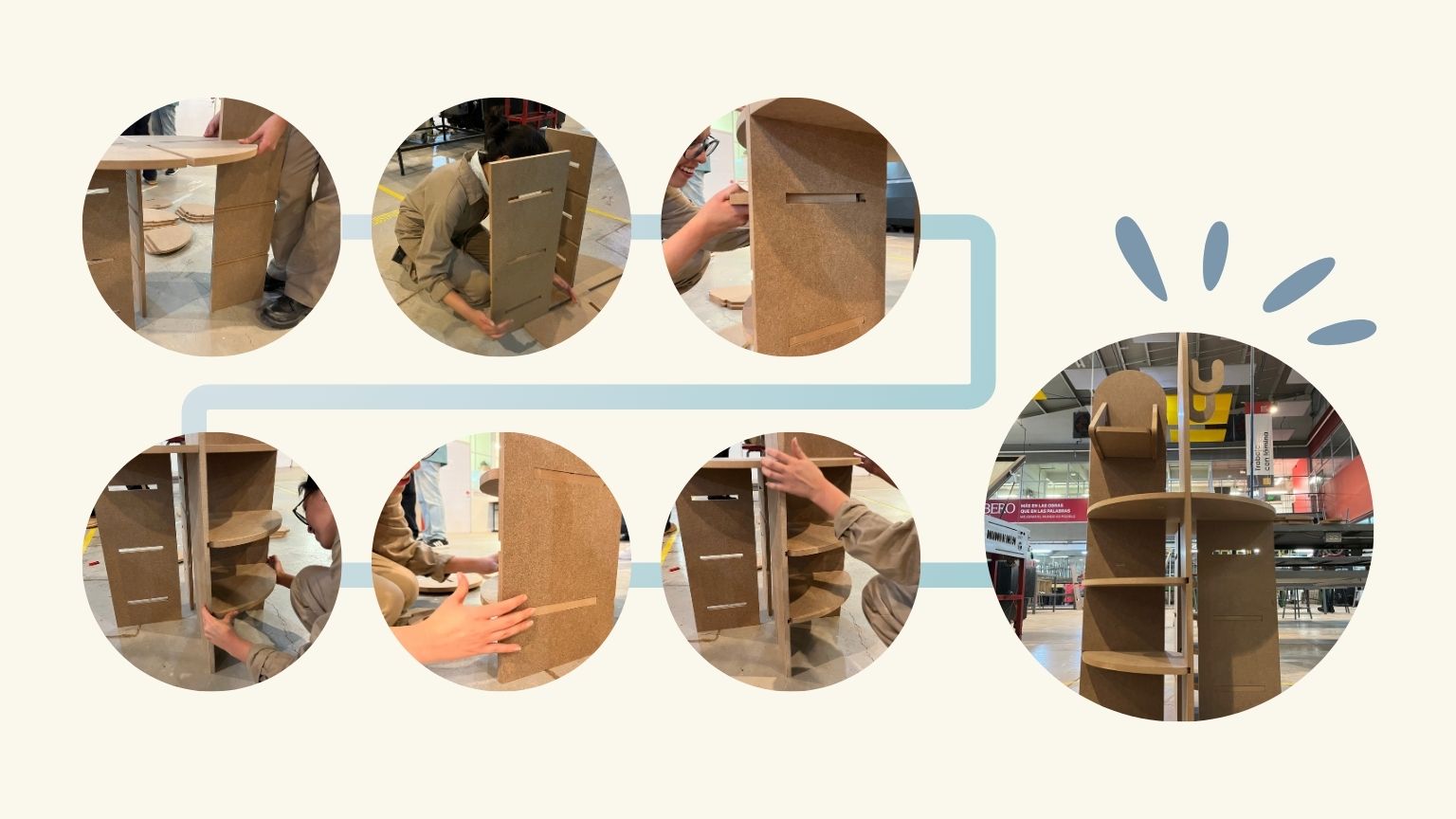
Note: With the corrections made the assembly was easier to do.
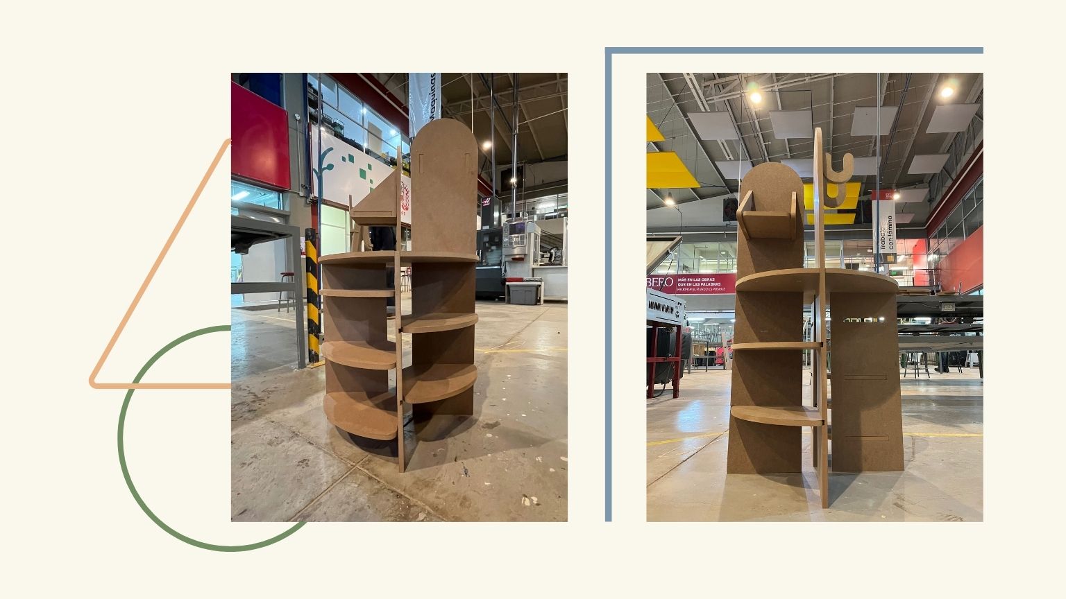
Result
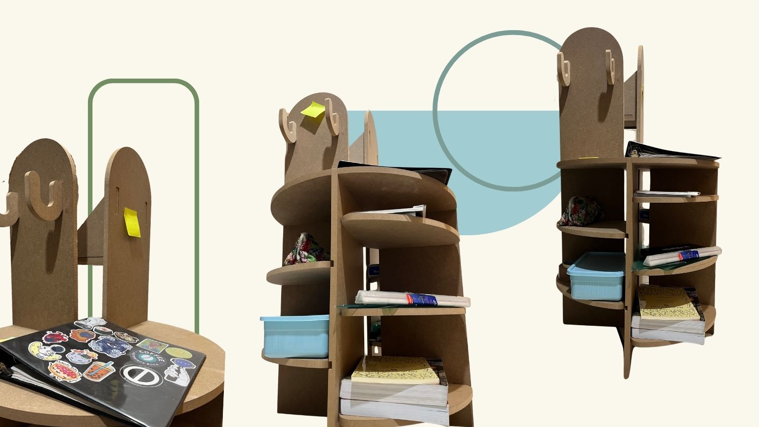
In use...
Conclusion
This week was undoubtedly a great challenge for me as an industrial designer. There are several aspects of design that should be taken into account but are often forgotten in the process. I learned a lot and am now more aware of the different aspects at both the design and production levels that must be considered when designing an object with the CNC.