6. Embedded programming
Let’s start at the beginning
What is programming?
The term 'program' comes from the Greek words 'pro' (before) and 'graphein' (to write) ). Originally, it referred to the act of writing ahead of time. Although it was not used to describe writing computer instructions 2000 years ago, it still accurately describes what we mean by 'computer programming' or simply 'programming.' When programming a computer, we write instructions that it must obey before executing them (Dicken, n.d.).
Important Note:
Computers are extremely good at following instructions. Unlike humans, they lack creativity and instinct. Therefore, it is crucial to be specific when instructing a machine.
Microcontroller
The RPS2040, developed by Raspberry Pi, is a dual-core ARM Cortex+MO+microcontroller with versatile I/O capabilities (PIO!), making ir ideal for projects requiring multitasking and connectivity.
Features:
- Programming: UF2
- How to program: USB mass-storage boot mode, drag-and-drop programming
- 32 bits --> 133 MHz (--> 250MHz overclocking)
- Dual ARM Cortex-M0+
- Hardcoded bootloader – XIO module or RPi Zero
- Sandbox board
- Clock speed: Up to 133 MHz
- Storage: 264KB of SRAM, and 2MB of on-board Flash memory
- I/O pins: 30 GPIO pins
- Power: 1.8V - 5.5V
- Bluethooth and Wifi: No
- Special Functions: USB 1.1 Host/Device, 8 Programmable I/O (PIO) state machines
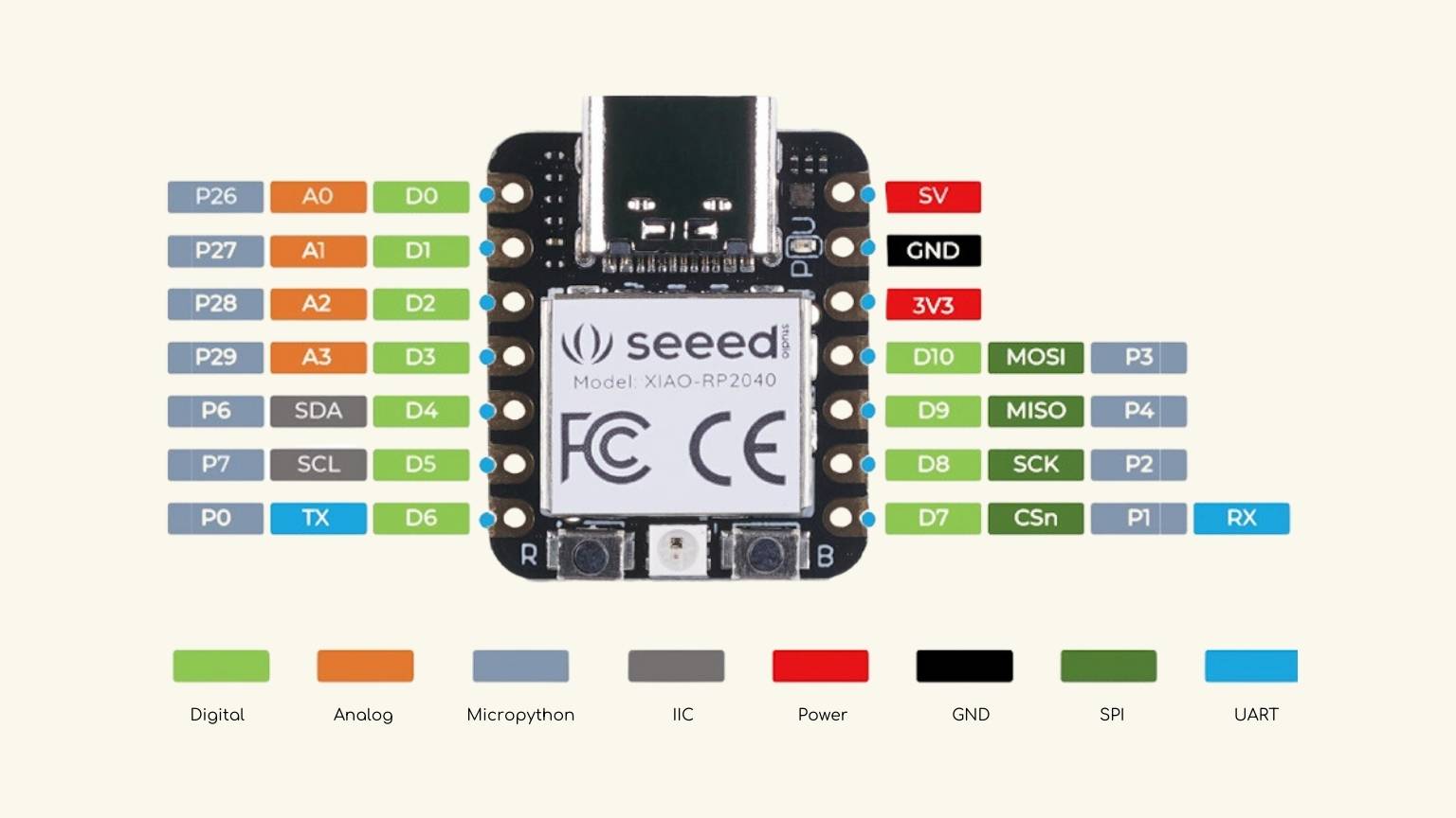
PCB
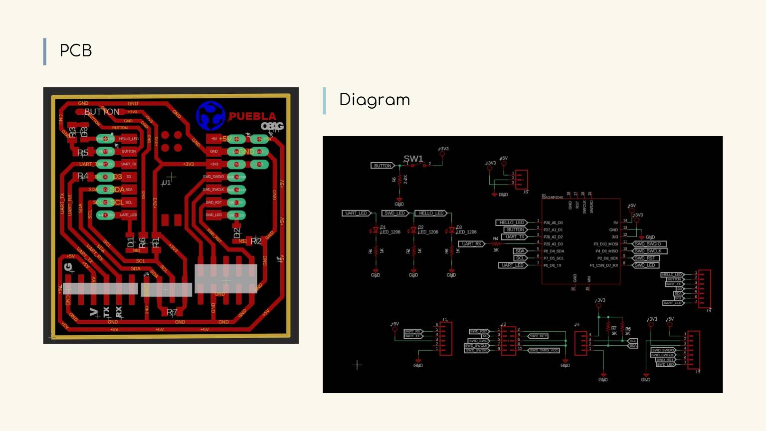
To learn more about its manufacture, go to my week 04
Languages
When programming a computer, it is important to consider the language used to instruct it. Instructions can be transmitted in a variety of languages, similar to human language. Some languages, like Spanish and Portuguese, have similar grammar and alphabets, while others use separate alphabets, such as Latin and Cantonese. It is important to note that some of these languages are old, while others have evolved over the last few hundred years.
Each language has its own set of advantages, disadvantages, similarities, and distinctions. The world's most widely used computer languages are Java, Python, C, and Javascript.
It's important to choose the right language for your project.
Comparisson
| Language | Description | Advantages | Disadvantage |
| C & C++ | C++ is a widely used object-oriented programming language for creating large-scale applications. It is a superset of the C language. |
|
|
| Rust | Rust is a blazing fast and memory-efficient static compiled language with a rich type system and ownership model. |
|
|
| Circuit Python | CircuitPython is a programming language designed to simplify experimenting and learning to code on low-cost microcontroller boards. |
|
|
| MicroPython | MicroPython is a tiny open source Python programming language interpretor that runs on small embedded development boards. |
|
|
Later on, I will explain the specific features of the Arduino and Circuit Python programming languages. For more information, please refer to the Fab Lab Puebla group page.
Group Assignment
And you can visit our group assignment by clicking on the button below.
Let’s start to program… or to try
First practice
I started with something simple: program an LED to light up.
Arduino-C++
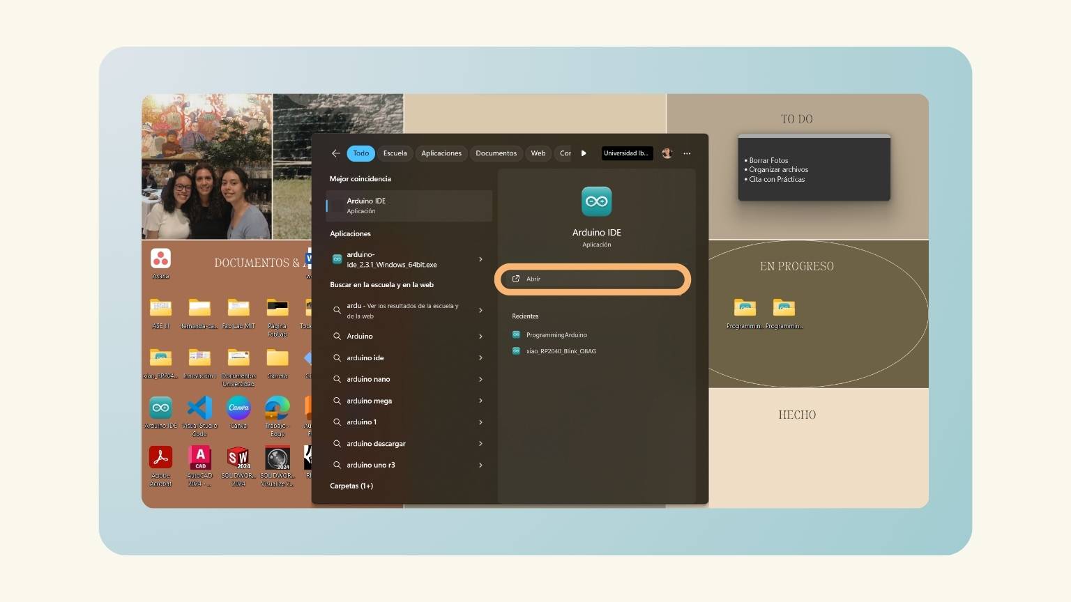
- First, I opened Arduino.
- In week 4, I had already connected the Seeed Studio XIAO RP2040 and programmed it with Arduino to test the operation of the PCB. A recapitulation of the steps:
- Launch the Arduino application.
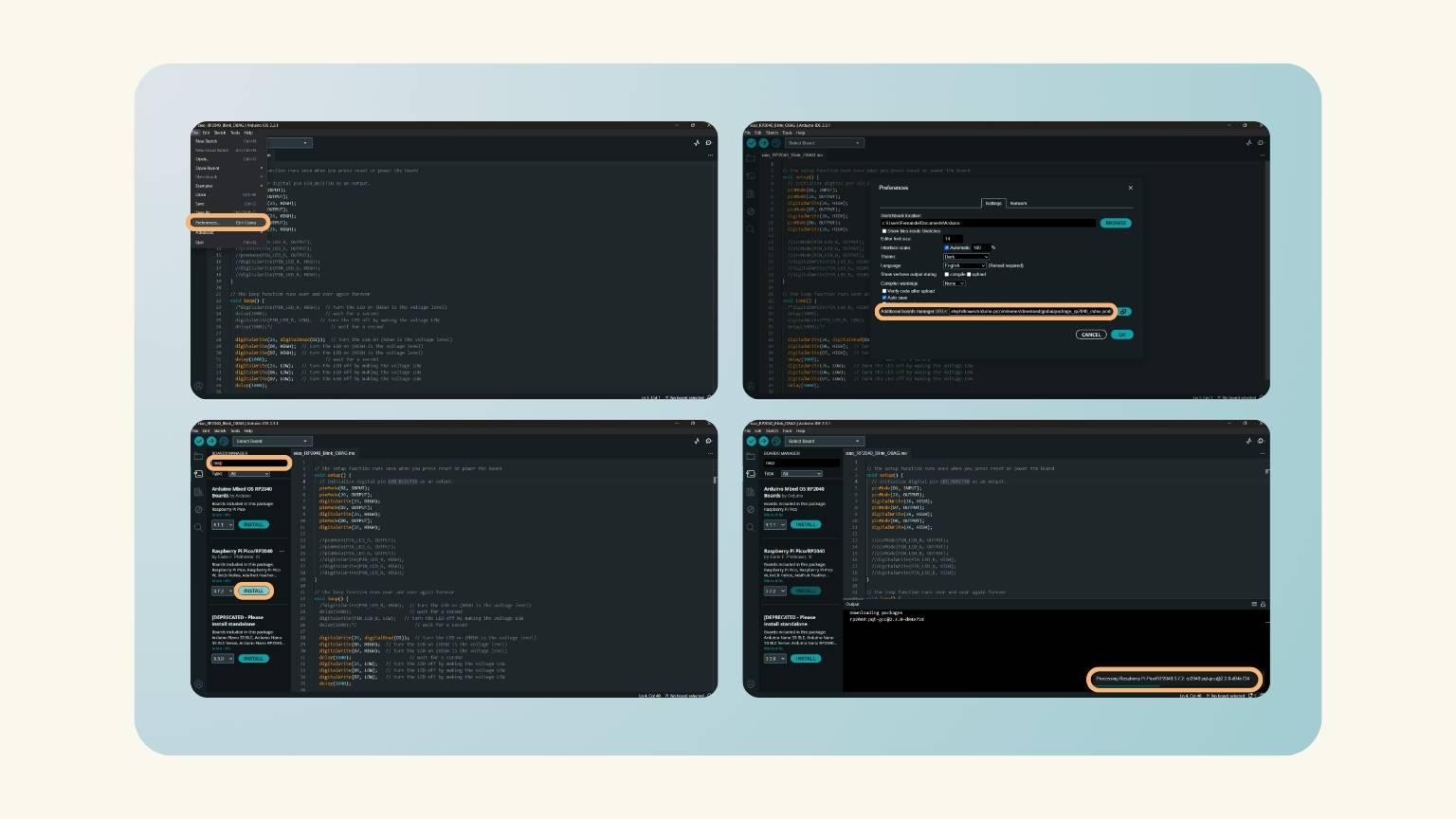
- Add the Seeed Studio XIAO RP2040 board package to your Arduino IDE.
- I navigated to ‘File’ > ‘Preferences’ and filled ‘Additional Boards Manager URLs’ with the url below: https://github.com/earlephilhower/arduino-pico/releases/download/global/package_rp2040_index.json
- Then, in the ‘Boards Manager', I searched for raspberry and installed the second option, ‘Raspberry Pi Pico/RP2040'.
- The installation was processed.
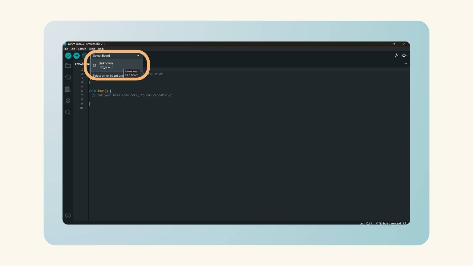
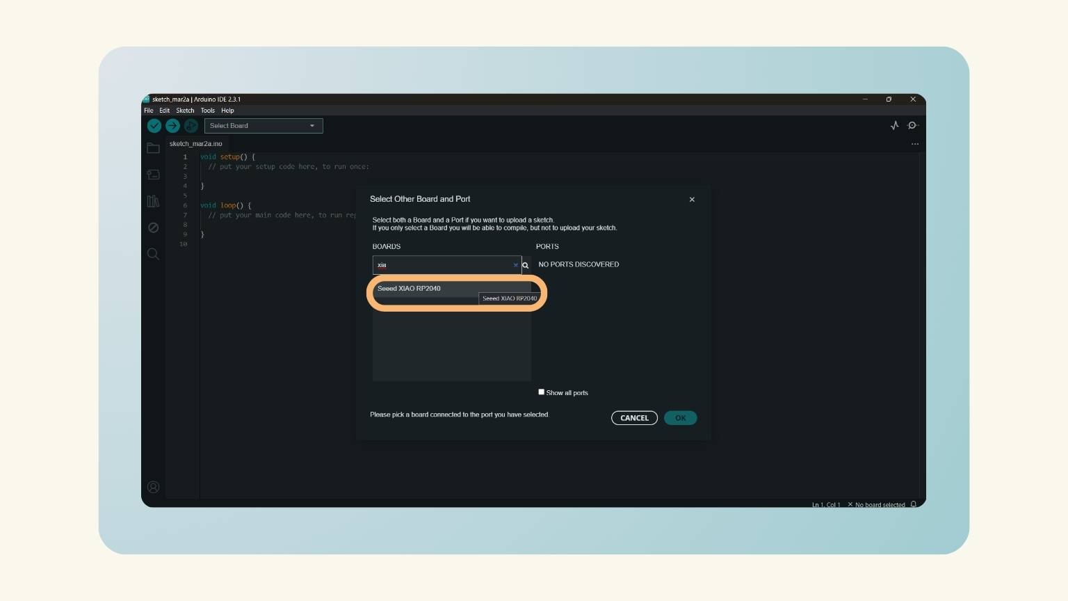
- After, I pressed the menu ‘Select Other Board and Port’ to put the board of the xiao.
- In the ‘Board’ option, I selected ‘SeedXIAO RP2040', and after the ‘Port’, in this case, the ‘COM3 Serial Port (USB)’.
- I started to write the code.

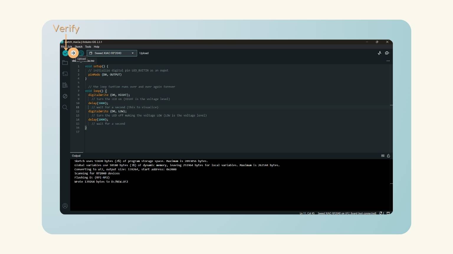
- To this end, first in the ‘void setup', I declare the pin D0 as an output.
- Then, in the ‘void loop', I started to use the function of ‘digitalWrite’ for writing a HIGH value to the digital pin.
- I used the function ‘delay’ to pause the program for the amount of time (in milliseconds) specified as a parameter.
- I used the function ‘digitalWrite’ for writing a LOW value to the digital pin.
- And I put a ‘delay’ to have a pause between the following actions.
- This was the code that I made:
- I uploaded the code.
- Note: After doing that, I recommend verifying the code with the ‘Verify' option.
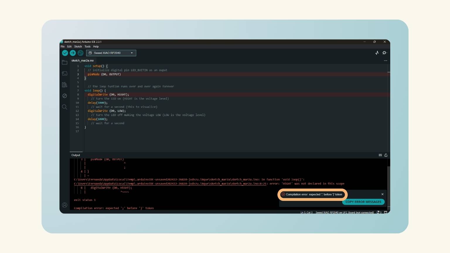
- So, I presented some mistakes in the code.
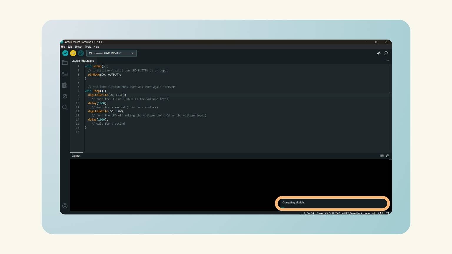
- I corrected them and re-uploaded the code. But first, I compiled the sketch.
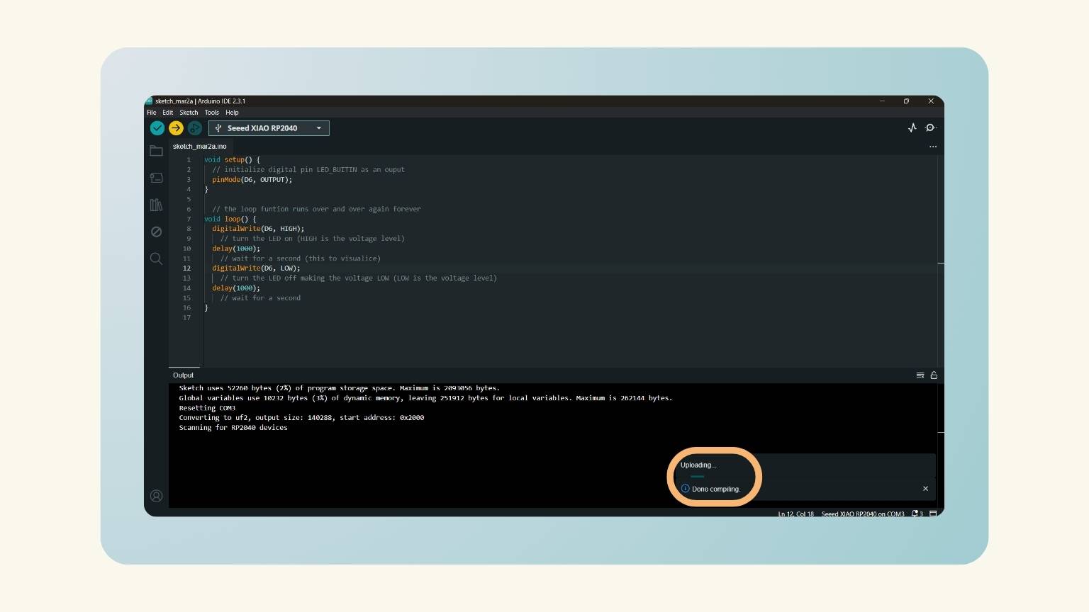
- Now, the code has been uploaded.
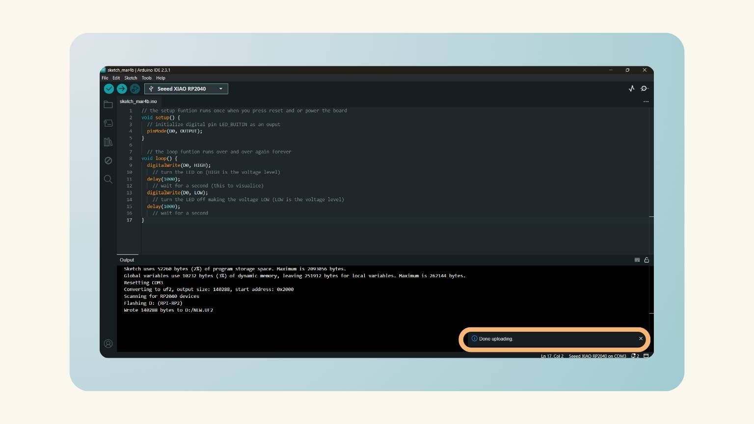
- Finally, the uploading was done.
Circuit Python
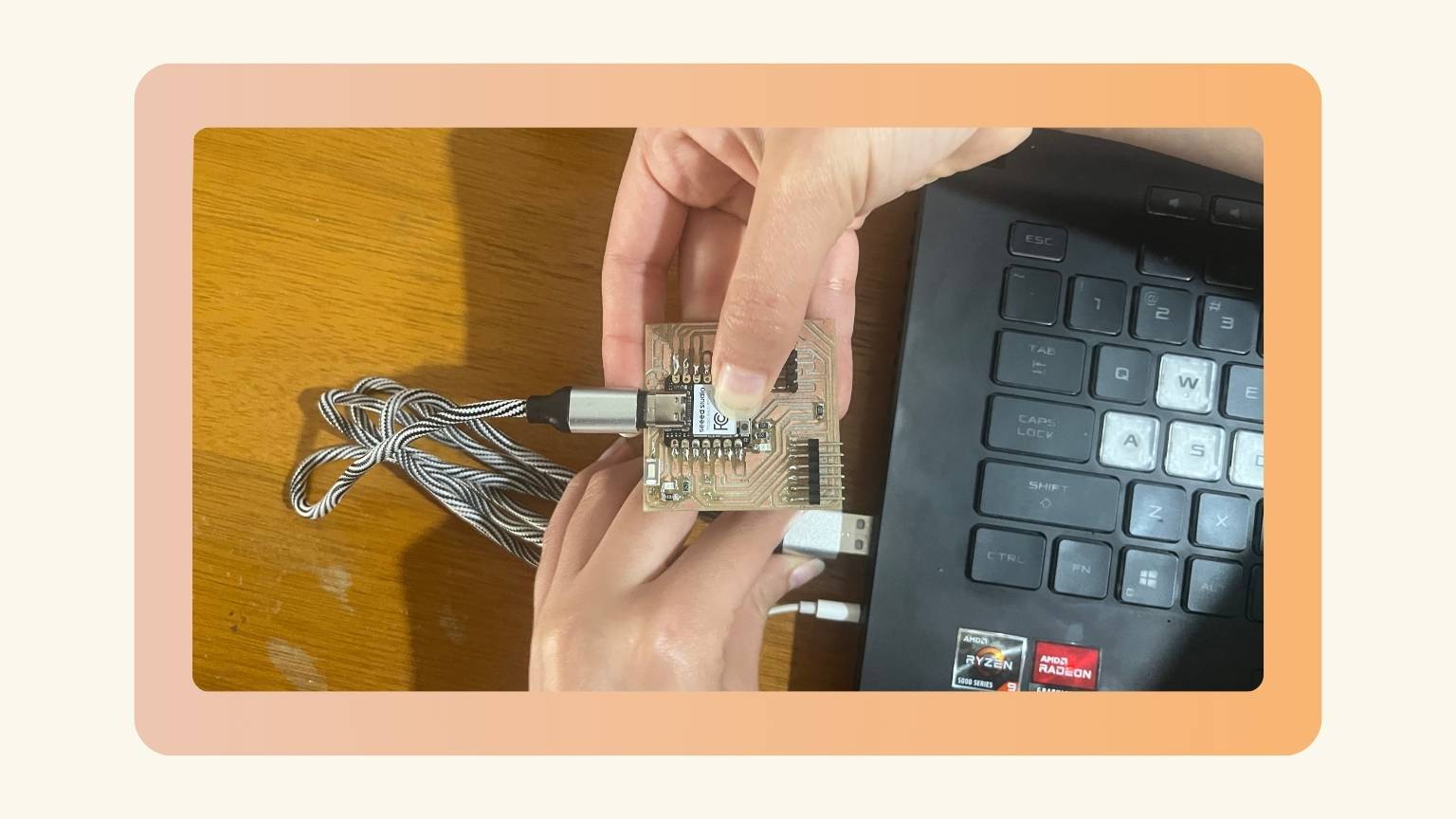
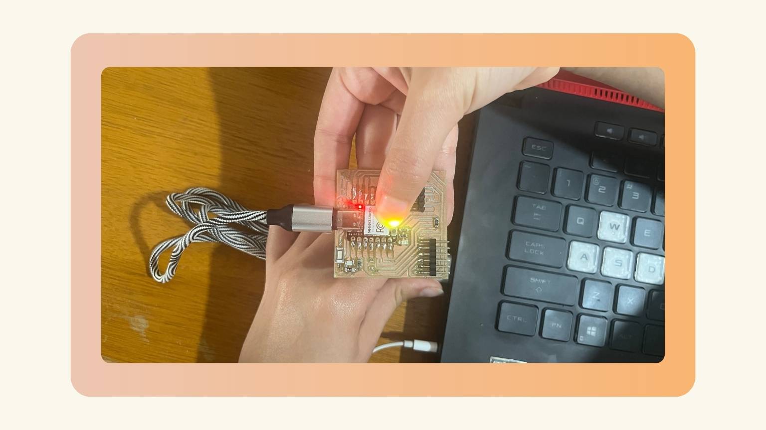
- First, I connected the PCB to my computer.
- When the PCB switched on, the lights of the xiao came on.
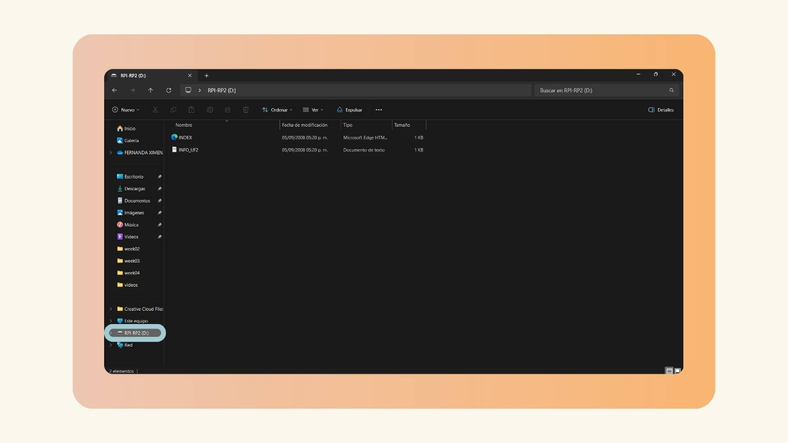
- Then, the PCB appears as a USB flash drive, in this case, ‘RPI-RP2 (D:).
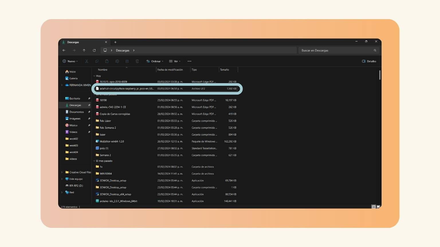
- So, I downloaded the library of the Xiao from the group page.
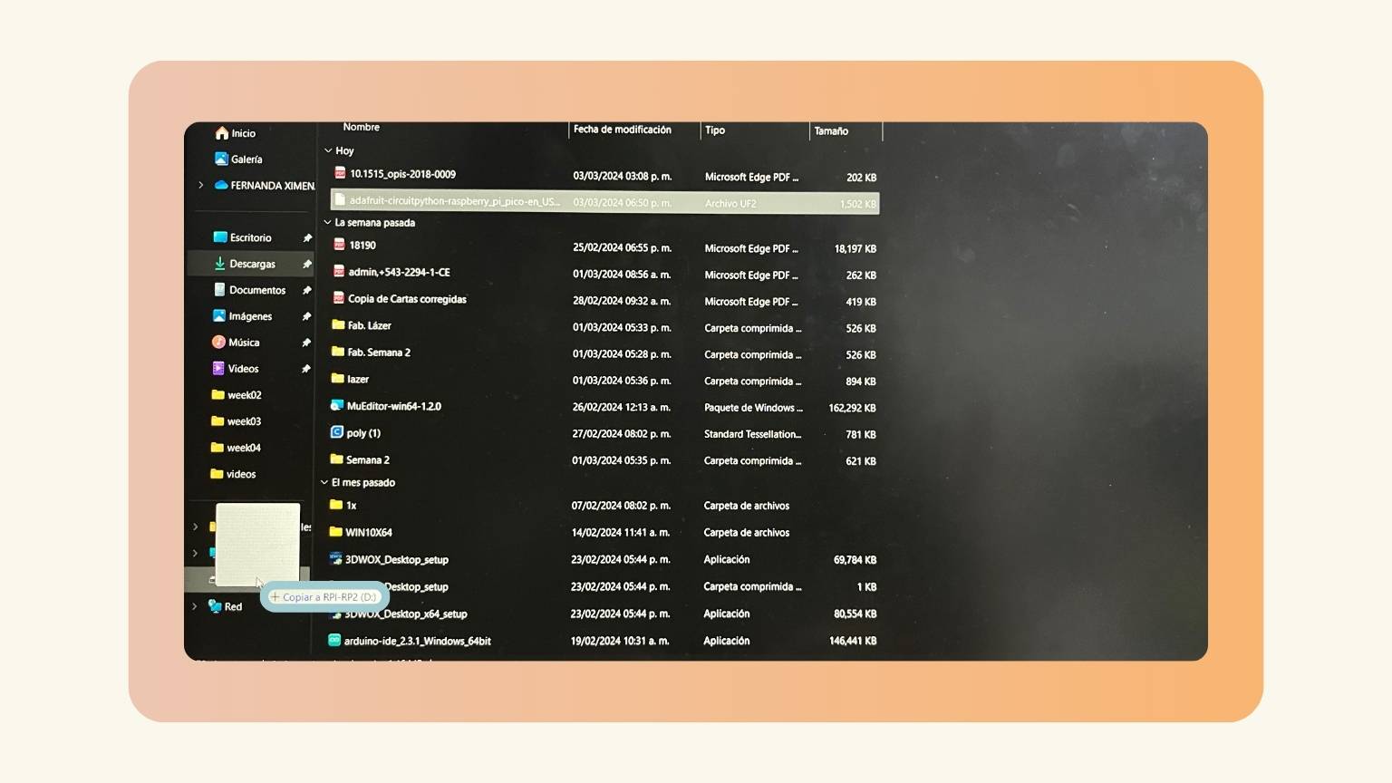
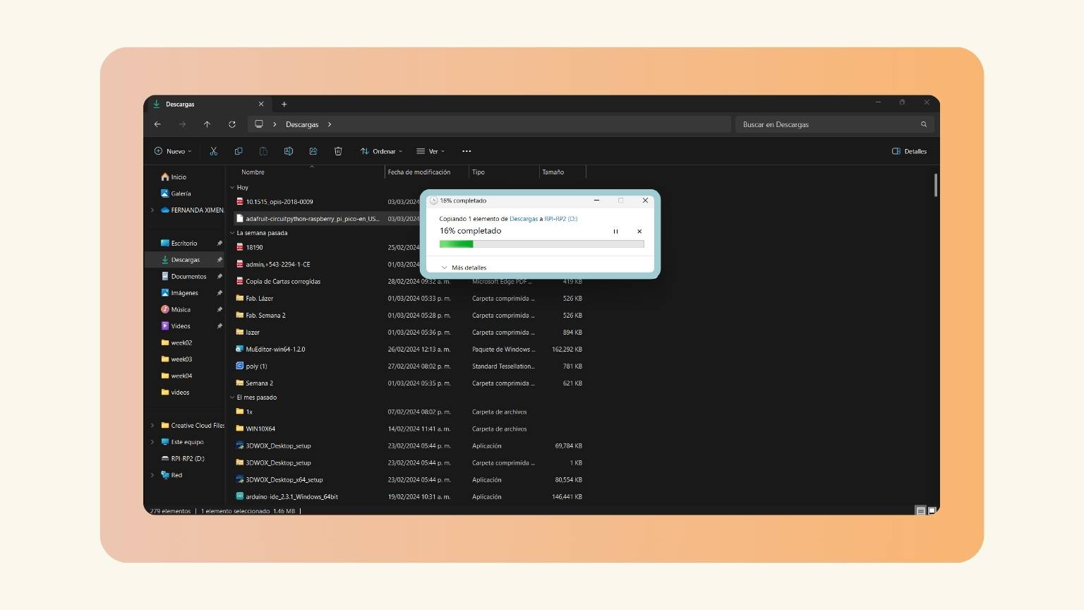
- I copied the file to the USB.
- The copy started to load.
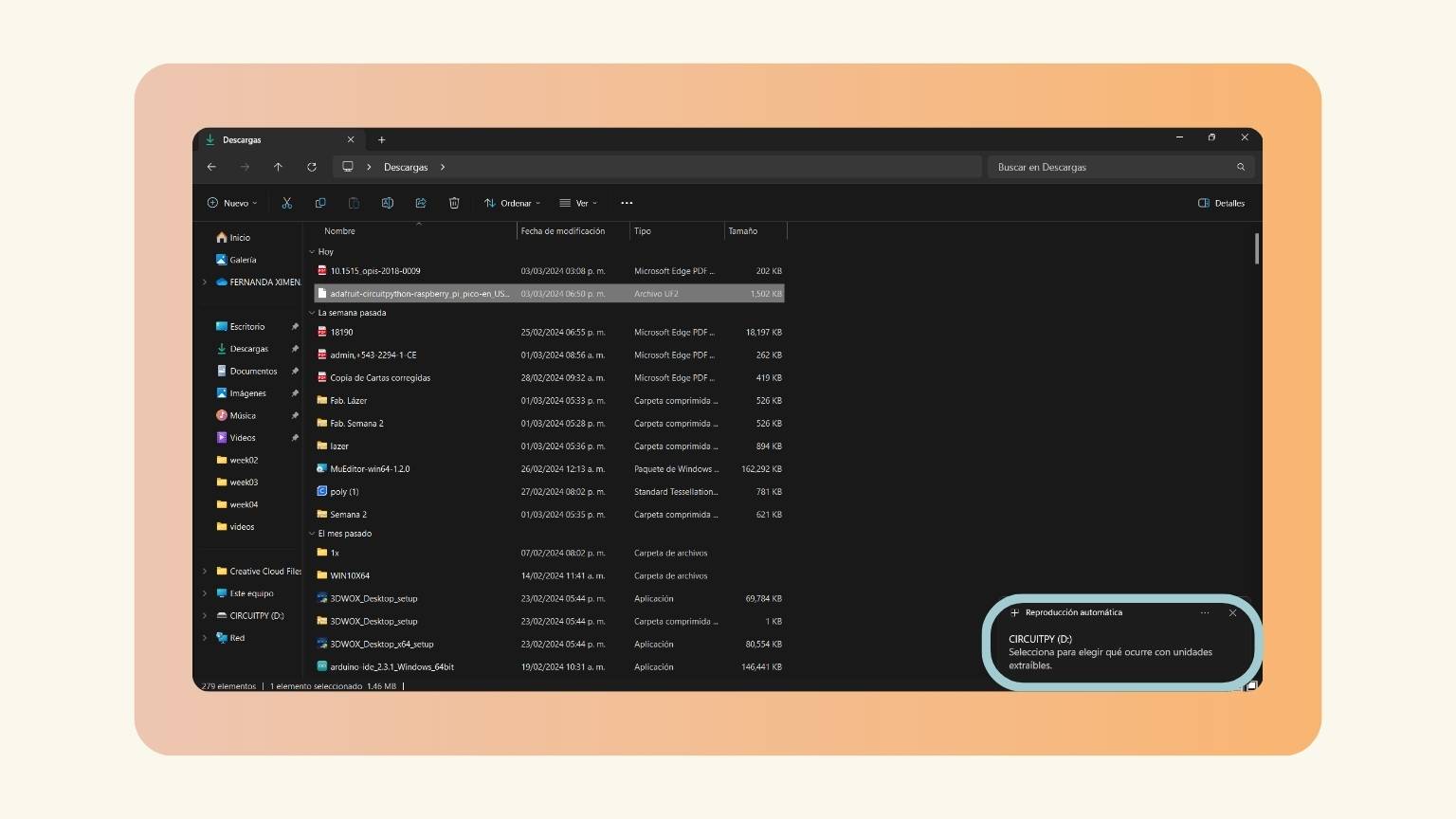
- And the USB changed its name to ‘CICUITPY (D:).
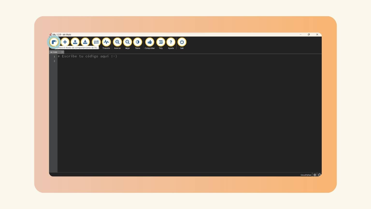
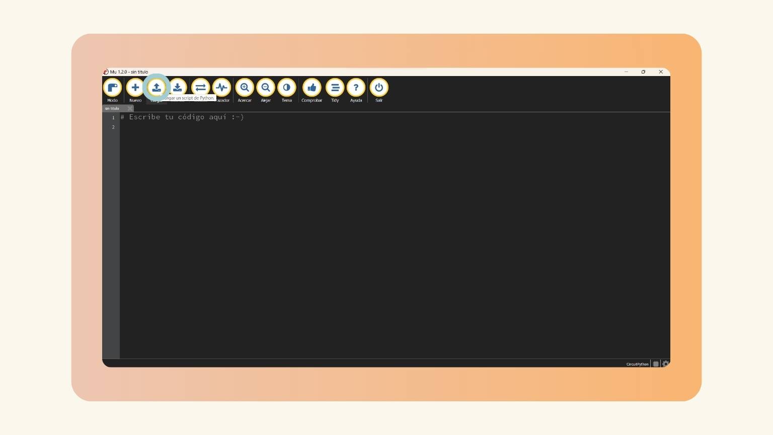
- I opened MU Editor in Circuit Python.
- I pressed the first option of the menu, ‘Mode’.
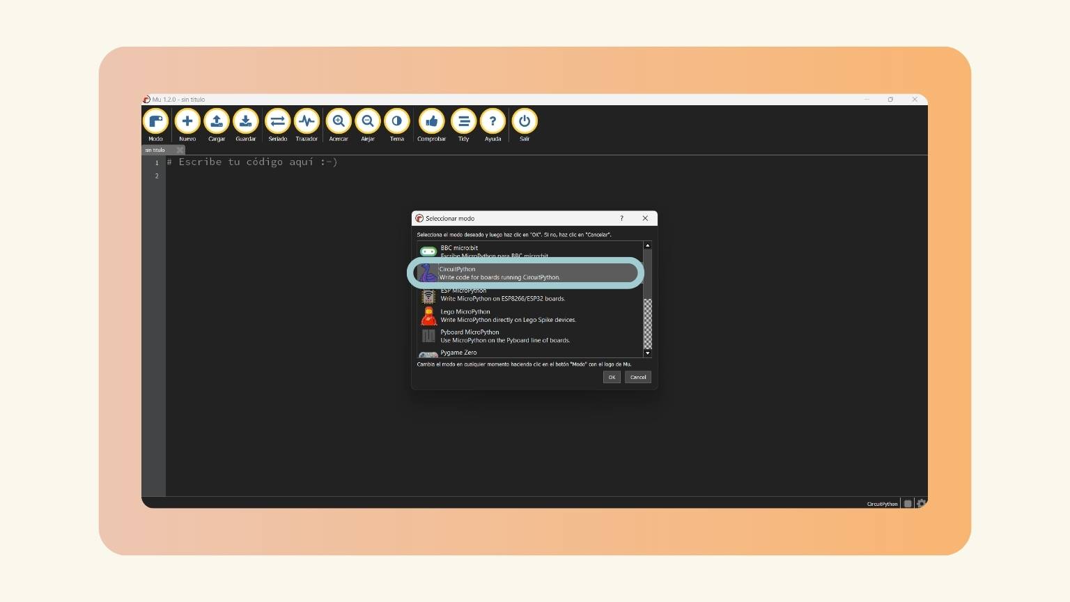
- I selected the Circuit Python option.
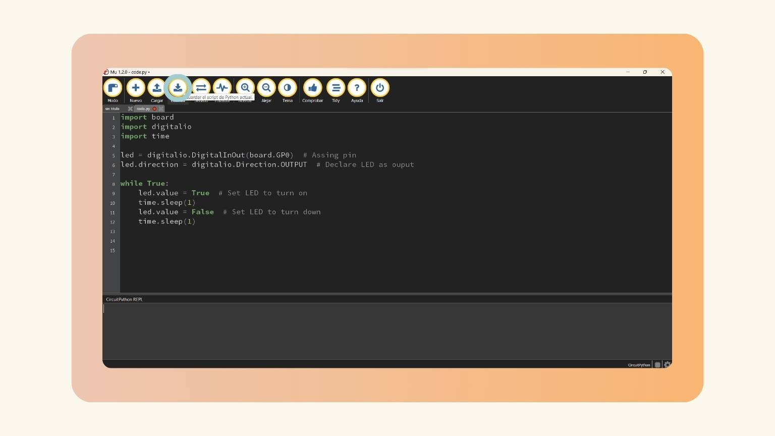
- Before starting to write the code, I downloaded the Python script.
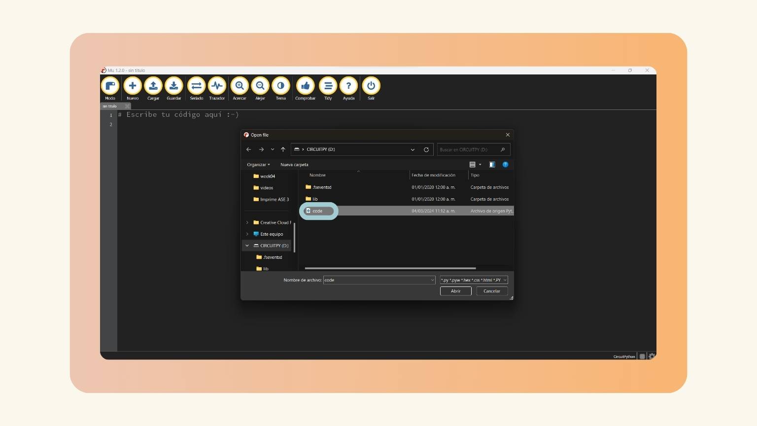
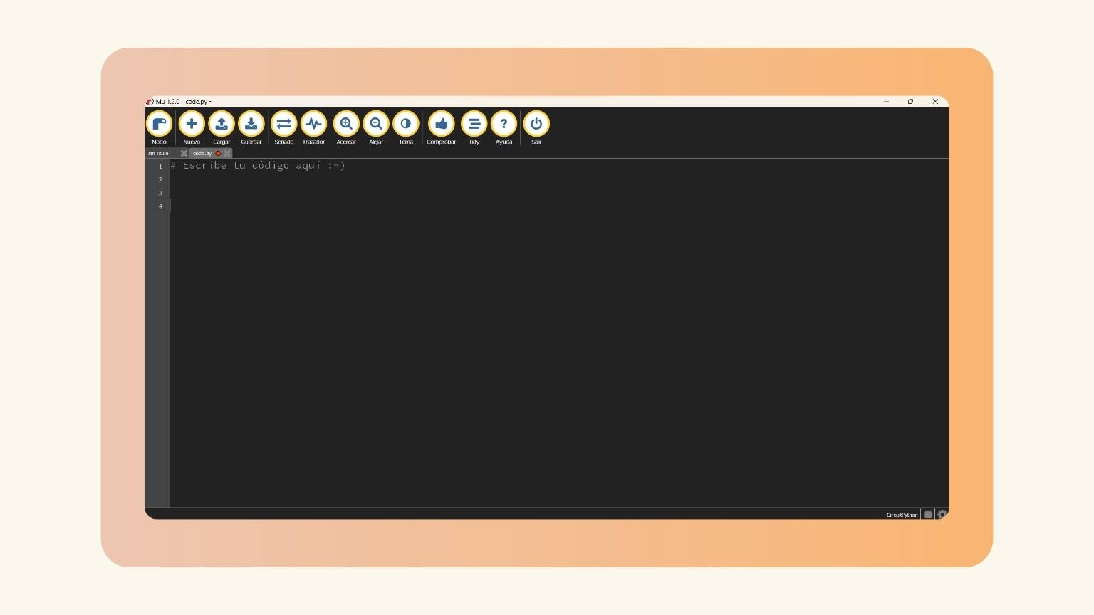
- I opened the ‘code’ file.
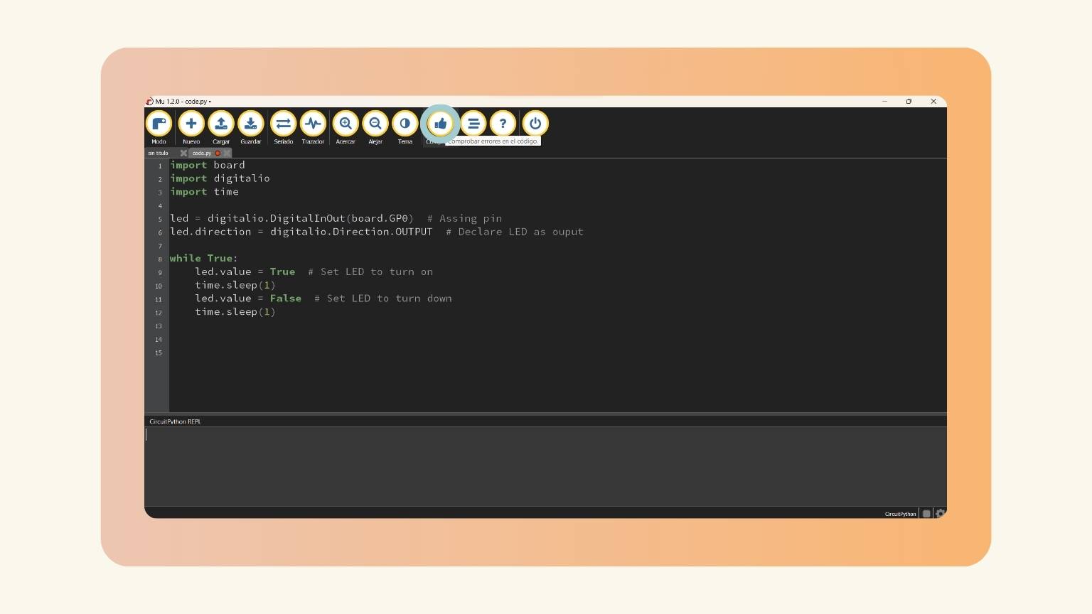
- After that, I started to write the code.

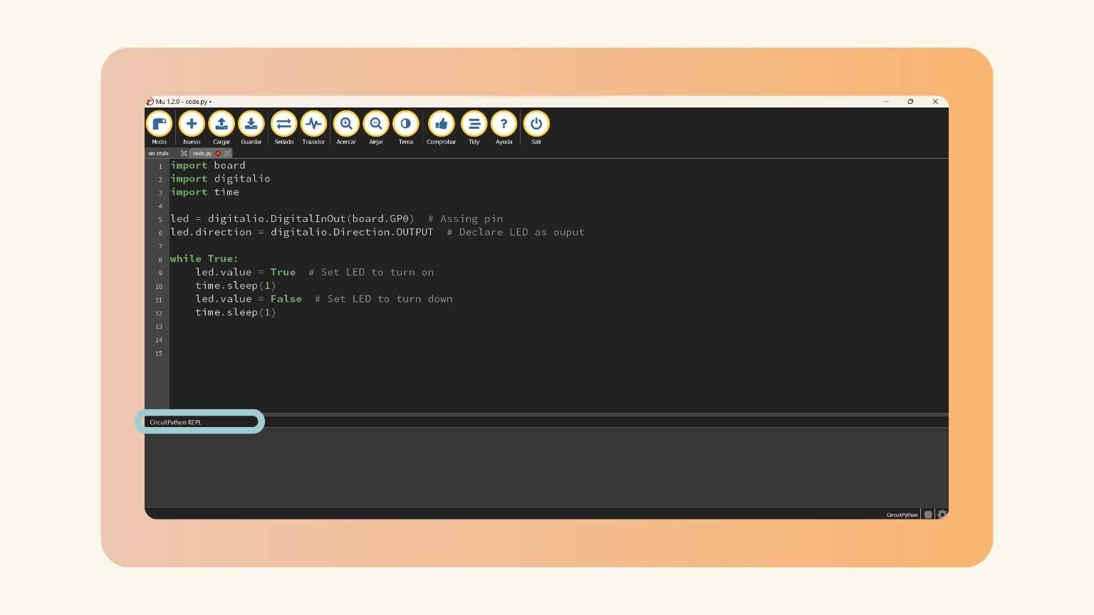
- First, I started to put the ‘import’ statement and included the name of the module or libraries that I imported.
- I declared the name of the pin to be equal to the ‘digitalio’ module to provide access to basic digital IO. Then, I placed a point and the ‘DigitalInOut’ to digitally control I/O pins, and in parenthesis, I put board.numberPin.
- In another line, I put the name of the pin, a point, and the ‘direction’ module to define the direction of a digital pin. So, next, I wrote ‘ digitalio.Direction.OUTPUT ‘ to declare the pin as an output.
- I put the name of the pin, a point, and the ‘value’ module to set the LED on. In this case, I equals ‘True’,
- And I wrote ‘time.sleep(1)’ to determine that the led would light for one second.
- I defined the second value of the condition as ‘False to determine which led should be paid.
- And, I wrote ‘time.sleep(1)’ to determine that the led should turn off for one second and then continue with the next action.
- This was the code that I made:
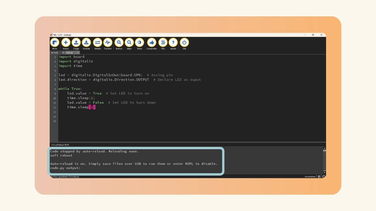
- Then, I selected the ‘Serial’ option to communicate with Python Interpreter.
- Now, I saw the ’REPL’, Read, Evaluate, Print and Loop.
- I verified that the code was correct.
- So, I saved the code.
- And the PCB began to reflect the programmed action.
Second practice
The action to be programmed was that, through the button, one of the LEDs would light up, but only when the LED was pressed; if it wasn’t pressed, nothing would be seen.
Arduino-C++
- So, I repeated the first steps to write the code in Arduino.
- I started the code.
- To do this, first I out the ‘int’ variable to declare the state.
- Then, in the ‘void setup', I declare the pin 27 as an input and the pin D0 as an output to the ‘pinMode’ function.
- I put a ‘if’ structure to make a condition and executed the following statement if the condition is 'true'.
- I wrote the condition using the function ‘digitalWrite’ for writing a HIGH value to the digital pin.
- And then I put ‘else’ structure to execute the condition of the statement if the 'if' statement is false.
- I used the function ‘digitalWrite’ for writing a LOW value to the digital pin.
- And this was the code:
- Then, I upload the code.
- And this was the result.
Circuit Python
To ’ Circuit Python’ was the same.
But the code changed a little; I didn’t explain that in the first example, but I think it’s important. To explain, I will use the following comparison:
| Action | Arduino | Circuit Python | |
| Define Pin | Use ‘define’ | - - - | |
| Initialize pins | Put ‘pinMode’, and in parentheses, note the pin name, separated with a comma if it is an output or input. | Write the name of the pin, and next = digitalio.DigitalInOut(board.pinNumber) | |
| Output | Put ‘pinMode’, and in parentheses, note the pin name, separated with a comma if it is an output or input. | Write the name of the pin and next =(NumberPin, NamePin.IN, NamePin.PULL_DOWN). | |
| Input | Put ‘pinMode’, and in parentheses note the pin name and separated with a comma if it is an output or input. | Write the name of the pin and next =(NumberPin, NamePin.OUT). | |
| Write | Put ‘digitalWrite’ >, and in parentheses, note the pin name, separated with a the state of the pin. | Write the pin name and after put a point followed by the word ‘value’. Then, this is declared as equal to true or false. | |
| Library Import | In the software, import the necessary library in the ‘Library Manager’ | Use the variable ‘import after downloading the respective library on the page of Circuit Python | |
| Loop | Use the ‘loop’ structure, and loops consecutively, allowing your program to change and respond. | Use ‘while’ to create loop continuously, and infinitely, until the expression inside the parenthesis, () becomes false. | Read | Put ‘digitalRead’ >, and in parentheses note the pin name. | Write the pin name and after put a point followed by the word ‘value’. Then, this is declared |
- I started to write the code.
- First, I started to put the ‘import’ statement and included the name of the module or libraries that I imported.
- For the LED and button, I declared the name of the pin as equal to the ‘digitalio’ module to provide access to basic digital IO.
- Then, I placed a point and the ‘DigitalInOut’ to digitally control I/O pins, and in parenthesis, I put board.numberPin.
- For the LED, In another line, I put the name of the pin, a point, and the ‘direction’ module to define the direction of a digital pin. Next, I wrote ‘ digitalio.Direction.OUTPUT ‘ to declare the pin as an output.
- For the button, I put the name of the pin, a point, and the ‘direction’ module to define the direction of a digital pin. Next, I wrote ‘ digitalio.Direction.INPUT ‘ to declare the pin as an output.
- And in another line, I put the name of the button, a point, and the ‘pull’ module to declare that if the button is not pressed, an action will not be executed. To this, I wrote ‘ digitalio.Pull.DOWN’.
- Then, I used the ‘while True’ loop for the board to execute the function and continue to do so as long as the board is powered on.
- I declare the state as the value of the button.
- I created a ‘if statement that says that if the value is true, the LED will be on.
- I put the name of the pin, a point, and the ‘value’ module to set the LED on. In this case, I equaled ‘True’.
- I put the ‘else’ statement so that if the condition is false, the led does not light up.
- I put the name of the pin, a point, and the ‘value’ module to set the LED off. In this case, I equaled ‘False’.
- So, this was the code that I made:
- Then, I verified if the code was correct.
- Finally, I saved the code.
- And the PCB began to reflect the programmed action.
Third practice
I wanted the LED to light up, but in the process, it increased in intensity little by little. To do this, I used the PWM function, which works by turning something on and off at a super-fast rate, and by changing how long it stays on versus how long it stays off, you can simulate "in-between" states.
Arduino-C++
- So, I repeated the first steps to write the code in Arduino.
- I started the code.
- I define the pins.
- I set the LED as an output.
- I used the ‘analogWrite’ function to define the pin and the intensity of the light.
- Then, I gave a duration to the action with the ‘delay’ function.
- And this was the code:
- Then, I upload the code.
- The action began on the PCB.
Circuit Python
- Now, in Circuit Python, I downloaded the Python script and opened the ‘code’ file.
- After that, I started to write the code.
- First, I started to put the ‘import’ statement and included the name of the module or libraries that I imported.
- I created a ‘PWMOut’ object on a LED pin. And in paratheses, after entering the pin number, two variables are added: ‘duty_cycle=0’ and ‘frequency=5000’.
- Then, I changed the ‘Duty Cycle Value’ to max 16 bits.
- After, I used the ‘while True’ loop for the board to execute the function and continue to do so as long as the board is powered on.
- I put the name of the pin, a point, and the ‘ duty_cycle'. Then equal to the intensity you wanted the LED to have.
- I determined the duration of the LED on time using the ‘time.sleep’ function. The duration I gave was one second at each intensity.
- So, this was the code that I made:
- I saved the code, and the PCB began to reflect the programmed action.
The code changed a little. To explain, I will use the following comparison:
| Action | Arduino | Circuit Python |
| Analog | Use the ‘analogWrite’ function. The pin will generate a steady rectangular wave of the specified duty cycle until the next call to analogWrite() (or a call to digitalRead() or digitalWrite()) on the same pin | - - - |
| Intensity | Use the ‘analogWrite’ function ad in the parentheses I put the name of the pin and the intensity followed by a coma. | Define the variable of led.duty_cycle and it’s given the desired value of intensity. |
| delay | Use the ‘delay’ to pauses the program for the amount of time (in milliseconds) specified as parameter. | Use the time.sleep() function to define the duration of the action. |
Fourth practice
I wanted to take the PWM to the next level, so now the LED would increase its intensity up to a certain value and once it reached that value, it would do the opposite, that is, once it reached the maximum point, the intensity would decrease until it reached the lowest value.
Arduino-C++
- I created a new sketch following the above steps for this programming
- I started to write the code:
- I declared the PWM, and equal to the pin.
- I declared a variable with ‘int’ and I gave it a value of 0.
- In the ‘void setup’, I defined the PWM on pin D7.
- I used the ‘pinMode’ to define the PWM as an output.
- In the repetitive cycle, I used ‘for’ to use as a summary. And the code show that the value of ‘i’ will be added to the value of ‘i’ until it reaches 255, this determines that when it reaches 255 the cycle will end, and the code will continue to be read.
- Then, I used the ‘analogWrite’ to define the PWM and its value ranging from 0 to 255.
- I determinate the duration of each intensity with the ‘delay’ function.
- I created another ‘for’ to make the invention function. That is to say that the intensity will now go from the highest to the lowest.
- I determinate the duration of each intensity.
- And this was the code:
- Then, I upload the code.
- And this was the result.
Circuit Python
- Now, in Circuit Python, I downloaded the Python script and opened the ‘code’ file.
- I wrote the code:
- First, I started to put the ‘import’ statement and included the name of the module or libraries that I imported.
- I created a ‘PWMOut’ object on a LED pin. And in paratheses after entering the pin number, two variables are added: ‘duty_cycle=0’ and ‘frequency=5000’.
- Then, I changed the ‘Duty Cycle Value’ to max 16 bit.
- After, I used the ‘while True’ loop for the board to execute the function and continue to do so as long as the board is powered on.
- I used the ‘for’ to use as a summary. The code show that the value of ‘i’ will be added to the value of ‘i’ until it reaches 255.
- I created a ‘if’ statement, where the condition says that if ‘i’ has a value less than 50 the lights must be turned on in a sequence from lesser to greater intensity.
- And I put the ‘else’ statement, which indicates that now, instead of turning on from lower to higher intensity, it will be inverted from higher to lower intensity.
- So, this was the code that I made:
- I saved the code, and the PCB began to reflect the programmed action.
The code changed a little. To explain, I will use the following comparison:
| Action | Arduino | Circuit Python |
| for | Use the ‘for’ structure to repeat a block of statements enclosed in curly braces. | Use the ‘for’ structure. |
| else | Use the ‘else’ structure. The clause (if at all exists) will be executed if the condition in the if statement results in false. | Use the ‘else’ structure. If the condition is not true, the else reflects the action to be performed. |
Fifth practice
Arduino-C++
Color Scale
- So, I repeated the first steps to write the code in Arduino.
- I began to write the code:
- I defined the LEDs pin for the three colors that I wanted to use.
- In the ‘void setup’, I declared all the LEDs as outputs.
- In the ‘void loop, I used the ‘setColor’ function to determine the RGB value of each color.
- And, after this function, I determined the duration of the lighting of each color.
- Then I created a ‘void setColor to execute the ‘analogWrite’ function for each color. This is intended to illuminate the LED in different shades.
- This was the code:
- The code has been uploaded.
- And the PCB began to reflect the programmed action.
The result was not as expected due to the type of LED; however, it was noticeable that the different color levels were detected, depending on the intensity of each one.
Neopixel
I utilized the neopixel example provided in the group page to test and understand the code. The only modification I made was to adjust the RGB.
The code is this:
So, this was the result:
Sixth practice
I decided to test the operation of an interruption, which is to immediately pause whatever the device is doing, check what is needed (such as turning on a light by pressing a button) and then go back to what it was doing before. In this way, the device can react instantly to important things without having to constantly stop and check, which makes it much more efficient.
Arduino-C++
- So, I repeated the first steps to write the code in Arduino.
- I started the code.
- I defined the LEDs and the button that I used.
- In the ‘void setup’ , first I declare the LEDs as an outputs.
- Then, I declared the button as an input.
- And then I create an interrupt. To this, I used the ‘attachInterrupt()’ function to attached an interrupt to a pin.
- So, I used ‘digitalPinToInterrupt(pin)’ to translate the actual digital pin to the specific interrupt number (in this case the button). Then, I named the interrupt and determined when the interrupt should be triggered.
- In the ‘void loop’, I used the function of ‘digitalWrite’ for writing the HIGH and Low values to the digital pin. as I wanted all my LEDs to light up, I set two of the LEDs to have the value of LOW and one to have the value of HIGH.
- I determinate that the duration of each ignition off for 1 second.
- I create a ‘void turnOnALL’. I gave it this name, since the ‘void’ variable is used in function declarations and in this case I had to determine the action of my interrupt.
- So, I wrote the code to execute when interrupt occurs.
- I used the ‘digitalWrite’ to declare that all the LED's will light up when the button is pressed.
- The duration I gave to this action was one second.
- This was the code:
- I saved the code.
- And the PCB began to reflect the programmed action.
Circuit Python
Note: In Circuit Python you can't execute an interrupt, so try to recreate the same action performed in Arduino but with other parameters.
- I downloaded the Python script and opened the ‘code’ file.
- I started to programming:
- First, I started to put the ‘import’ statement and included the name of the module or libraries that I imported.
- I declared the name of the LEDs pin and equal to the ‘digitalio’ module to provide access to basic digital IO.
- Then, I placed a point and the ‘DigitalInOut’ to digitally control I/O pins and in parenthesis I put ‘board.numberPin’.
- In another line I put the name of the pin, a point and the ‘direction’ module to define the direction of a digital pin. So, next I wrote ‘ digitalio.Direction.OUTPUT ‘ to declare the pin as an output.
- For the button, I put the name of the pin, a point and the ‘direction’ module to define the direction of a digital pin. So, next I wrote ‘ digitalio.Direction.INPUT ‘ to declare the pin as an output.
- And in another line, I put the name of button, a point and the ‘pull’ module to declare that if the button is not pressed, an action will not be executed. To this, I wrote ‘ digitalio.Pull.DOWN’.
- Then, I used the ‘while True’ loop for the board to execute the function and continue to do so as long as the board is powered on.
- I declare the state as the value of the button.
- I created a ‘if statement which says that if the value is true, the LEDs will be on.
- I put the name of the pin and a point and the ‘value’ module to set the LED on. In this case, I equal to ‘True’.
- I put the ‘else’ statement so that if the condition is false, only one of the LEDs would light up and the other two would remain off.
- I put the name of the pin and a point and the ‘value’ module to set the LED off. In this case, I equal to ‘False’ to the leds which would remain off and ‘True’ for the led that lights up.
- And for the ‘else’ statement, I set a duration of 1 second for each LED on.
- This was the code:
- I upload the code.
- And this was the result.
Sensors and programming
I added an audio sensor to my PCB to test the different elements that I could implement in the future, as well as to better understand how programming with external elements works.
So, let's see how I did with this ...
Programming Language: Arduino-C++
First practice
I created a code that uses a sound sensor to detect clapping and turn on an LED. The purpose of this project is to demonstrate the functionality of the sound sensor and its ability to trigger external elements.
How did I make the code?
- In the first step, I defined the sensor, LED, state, and value.
- In the 'void setup' section, I declared the LED as an output and the sensor as an input.
- In the 'void loop' section, I set the value to be determined by the sensor reading.
- I established a condition using the 'if' function to determine when the LED should light up.
- Additionally, I ensured that if the state of the LED changes, it will turn off or on again.
- Finally, I set the duration to be 0.5 seconds.
Code
Result
Second practice
The second objective is similar, as it aims to illuminate the LED based on the notes of a song.
How did I make the code?
- Fist I define the variables of the sensor, lecture od the sensor, LED, ‘a’ (to count the clap) and ‘b’ (to get put of the loop).
- In the 'void setup' section, I used the ‘Serial.begin’ to the serial communication.
- I declared the sensor as an output and the LED as an input.
- In the 'void loop' section, I put the execute program.
- I saved in the ‘lectureSensor’ the lecture of the reading microphone state. That is, it will if the sensor at that moment received a signal.
- Then, I set a condition that says that of there is a sensor reading it will be equal to HIGH, that is a clap.
- After, I determined that the ‘a’ is equal to ‘a + 1’. This reflects the fact that claps were detected and will continue to increase with every clap given.
- The ‘b’ variable equalized to 0, for enter to the loop.
- Then I established the duration of the lecture to 0.2 seconds. This it’s because when the signal bounces back and we get a lot of HIGHT readings. So, with this time the sensor only detected the last frequency of the clap.
- Then, I set another condition where we establish that if we have a clap and that b=0, then the LED will turn on.
- So, in the case of the past condition is true, we show if the LED light up. To show this, I inserted a ‘SerialPrintln’ function and the ‘digitalWrite’ function to show in the Serial Monitor the state of the LED.
- Again, I equalized the ‘b’ variable equalized to 0, for exit to the loop and don’t enter again.
- Next, I determined that the ‘a’ is equal to ‘2’. This reflects the fact that if two claps were detected (the first and this second), the LED will turn on.
- In the case that the above happens, we show if the LED doesn’t light up. To show this, I inserted a ‘SerialPrintln’ function and the ‘digitalWrite’ function to show in the Serial Monitor the state of the LED.
- Finally, I established that the ‘a’ value should be equal to 0, to return the counter to 0.
Code
Result
Conclusion
This week was challenging to understand since I had not encountered some of the programming terms before. This made it difficult to comprehend certain aspects of programming.
However, as I progressed with the practices, I gained a better understanding of how everything worked, including the use of functions. In the end, I obtained a comprehensive overview of embedded programming and was able to start testing with sensors, which I was very excited about achieving.