
13. Embedded Networking & Communications
In this week's work I connected a GPIO controller to a microcontroller in two different boards.
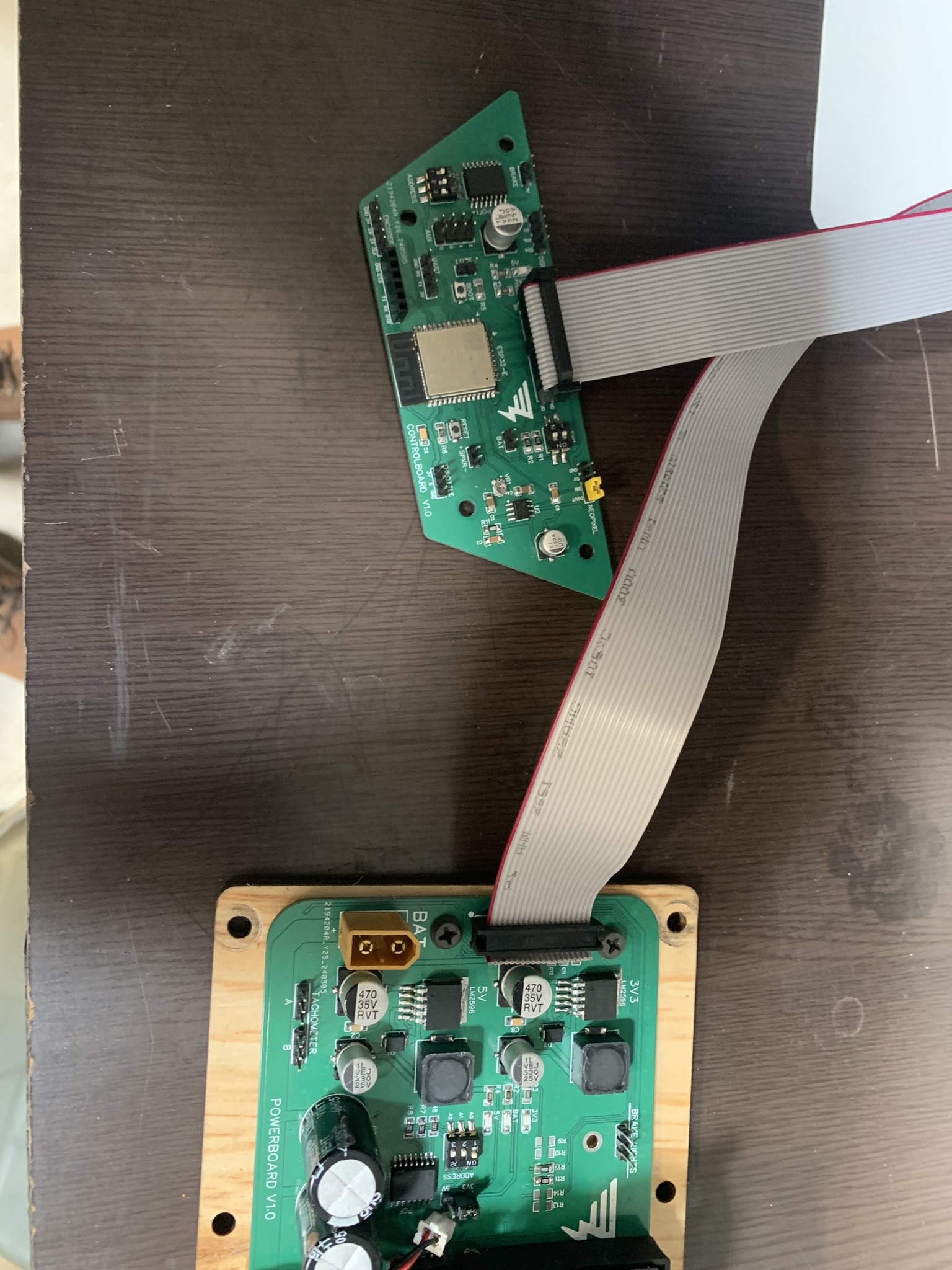
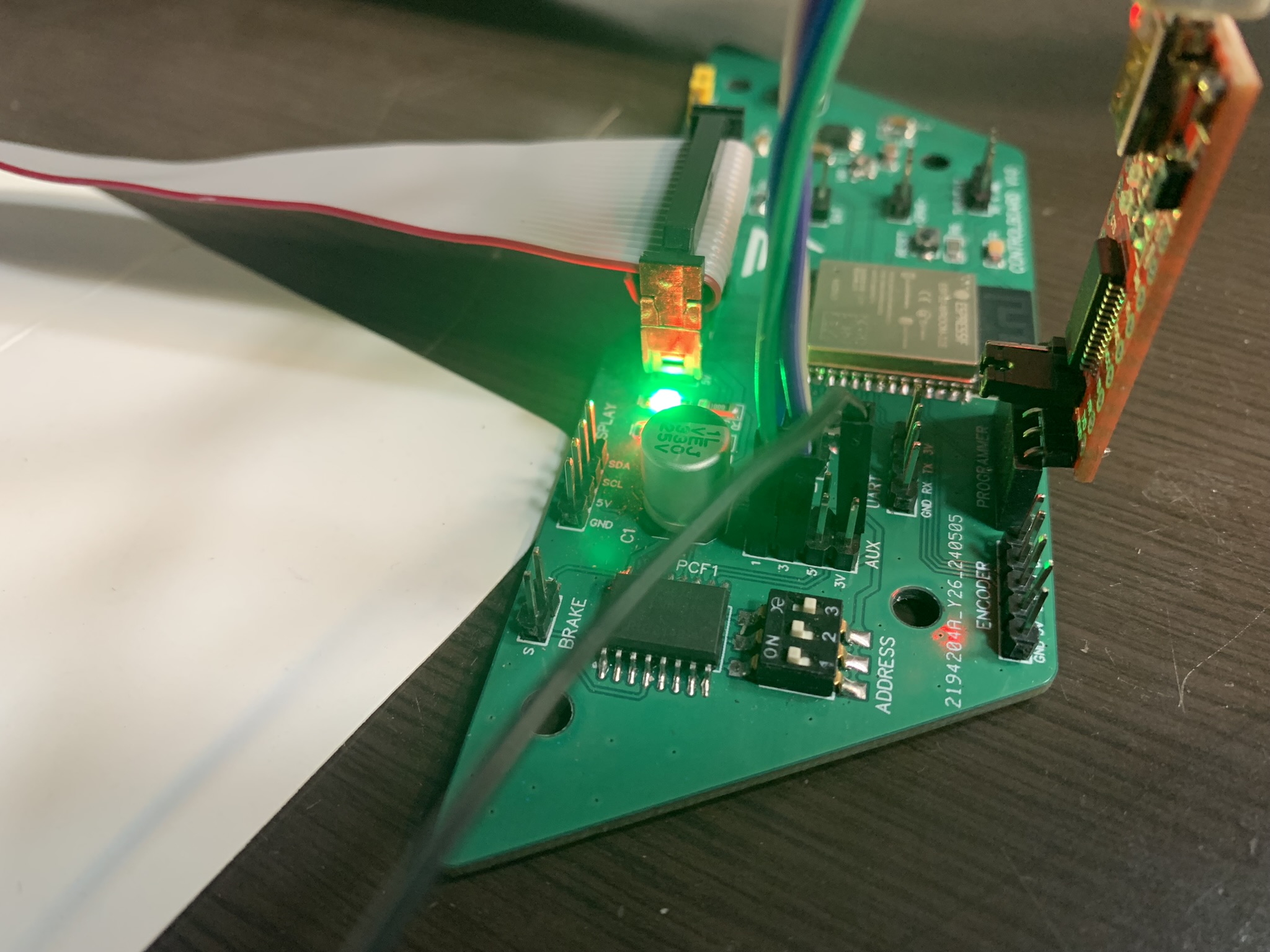
For my final proyect I designed two separate boards, a control board and a power board. The control board carries the main microcontroller, an ESP32, and its accompanying electronics, while the powerboard controls the motors and handles battery monitoring and voltage regulation. These two boards lay in different parts of my electric scooter, connected to each other by a long flat cable assembly. To reduce the number of cables needed to connect one board to the other, I used a GPIO expander, the PCF8574, which allows me to control up to 8 things on the powerboard without the need to run 8 individual cables, because this controller recieves its information using the i2C communication protocol.
Using this controller is really easy, we only need to now it's address on the i2C network and use the Adafruit_PCF8574 library to communicate with them. In my case I implemented a set of dip-switches that allow me to easily change each controller's address. Because there are two of this controllers in the i2C network.
To find each controller's address, we use the following sketch, which will scan the i2C network and show all the available devices:
	#include Wire.h

		void setup() {
		  Wire.begin();
		  Serial.begin(9600);
		  while (!Serial);             // Leonardo: wait for serial monitor
		  Serial.println("\nI2C Scanner");
		}

		void loop() {
		  byte error, address;
		  int nDevices;

		  Serial.println("Scanning...");

		  nDevices = 0;
		  for(address = 1; address < 127; address++ ) {
			Wire.beginTransmission(address);
			error = Wire.endTransmission();

			if (error == 0) {
			  Serial.print("I2C device found at address 0x");
			  if (address < 16)
				Serial.print("0");
			  Serial.print(address,HEX);
			  Serial.println("  !");
			  nDevices++;
			}
			else if (error == 4) {
			  Serial.print("Unknown error at address 0x");
			  if (address < 16)
				Serial.print("0");
			  Serial.println(address,HEX);
			}
		  }
		  if (nDevices == 0)
			Serial.println("No I2C devices found\n");
		  else
			Serial.println("done\n");

		  delay(5000);           // wait 5 seconds for next scan
		}
This program, uploaded to the ESP32, returns the following addresses:
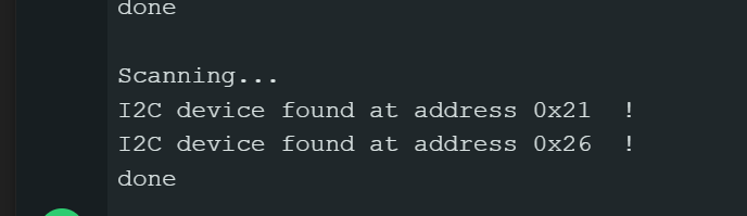
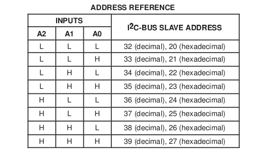
By moving the dip-switches and looking for address changes, we can identify the address for each controller, in this case I configured the controller on the controlboard on the 0x26 address and the one in the powerboard on 0x21. Now that we know the address for each controller, we can now get to use them as outputs or inputs. Alternatively we can use the truth table provided in the PCF8574's datasheet in order to know exactly how to set an specific address on the device.
Once we know the used addresses, using this code, we turn all the two controller's GPIO on and off every second:
	#include Wire.h
	#include Adafruit_PCF8574.h

	Adafruit_PCF8574 pcf1;
	Adafruit_PCF8574 pcf2;

	void setup() {
		Serial.begin(9600);
		while (!Serial);  // Wait for Serial monitor to open

		// Initialize both expanders
		if (!pcf1.begin(0x21)) {
		Serial.println("Couldn't find PCF8574 at 0x21");
		while (1);
		}
		if (!pcf2.begin(0x26)) {
		Serial.println("Couldn't find PCF8574 at 0x26");
		while (1);
		}

		// Set all pins to OUTPUT
		for (int i = 0; i < 8; i++) {
		pcf1.pinMode(i, OUTPUT);
		pcf2.pinMode(i, OUTPUT);
		}

		Serial.println("PCF8574 Output Test");
	}

	void loop() {
		// Turn all pins low (turn on LEDs if connected)
		for (int i = 0; i < 8; i++) {
		pcf1.digitalWrite(i, LOW);
		pcf2.digitalWrite(i, LOW);
		}
		delay(1000);

		// Turn all pins high (turn off LEDs if connected)
		for (int i = 0; i < 8; i++) {
		pcf1.digitalWrite(i, HIGH);
		pcf2.digitalWrite(i, HIGH);
		}
		delay(1000);
	}
To test that the outputs are really working, we can connect some LED's or check the output voltages with a multimeter. In my case I opted for the latter, because I had no easy way to connect LED's to the already soldered PCF's.
And they do work!
Now let's use the controllers as inputs! To do this we follow the same process, but declare as inputs the pinModes for all the GPIO's we want to use:
	#include Wire.h
	#include Adafruit_PCF8574.h

	Adafruit_PCF8574 pcf1;
	Adafruit_PCF8574 pcf2;

	void setup() {
		Serial.begin(9600);
		while (!Serial);  // Wait for Serial monitor to open

		// Initialize both expanders
		if (!pcf1.begin(0x21)) {
			Serial.println("Couldn't find PCF8574 at 0x21");
			while (1);
		}
		if (!pcf2.begin(0x26)) {
			Serial.println("Couldn't find PCF8574 at 0x26");
			while (1);
		}

		// Set all pins to INPUT
		for (int i = 0; i < 8; i++) {
			pcf1.pinMode(i, INPUT);
			pcf2.pinMode(i, INPUT);
		}

		Serial.println("PCF8574 Input Test");
	}

	void loop() {
		// Read from the first expander
		Serial.print("Inputs on expander 1: ");
		for (int i = 0; i < 8; i++) {
			Serial.print(pcf1.digitalRead(i));
		}
		Serial.println();

		// Read from the second expander
		Serial.print("Inputs on expander 2: ");
		for (int i = 0; i < 8; i++) {
			Serial.print(pcf2.digitalRead(i));
		}
		Serial.println();

		delay(1000);
	}
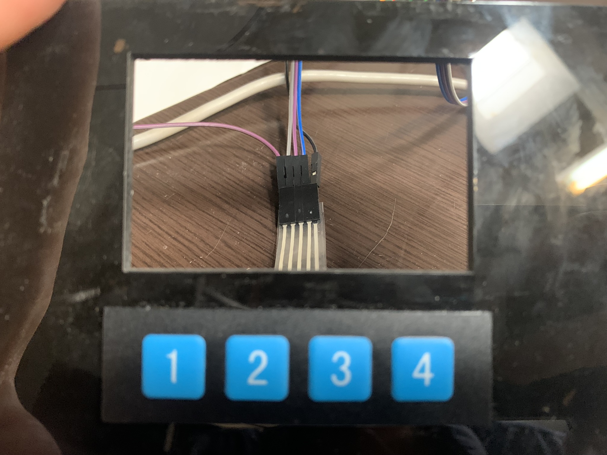
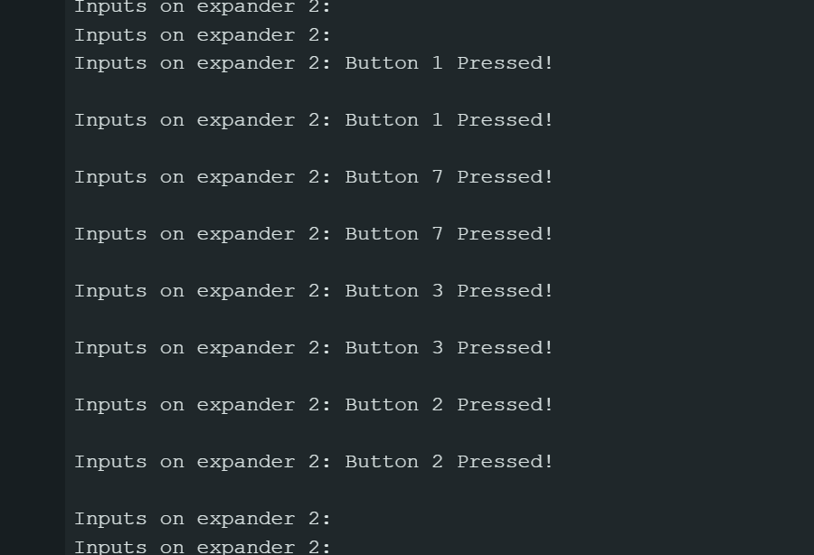
I connected to the controller on the control board a membrane 4 button array, in order to create some kind of "user interface" for the main controller on the scooter. The code that reads the inputs is the following:
	#include Wire.h
	#include Adafruit_PCF8574.h

	Adafruit_PCF8574 pcf2;

	void setup() {
		Serial.begin(9600);
		while (!Serial);  // Wait for Serial monitor to open

		if (!pcf2.begin(0x26)) {
			Serial.println("Couldn't find PCF8574 at 0x26");
			while (1);
		}

		// Set all pins to INPUT
		for (int i = 0; i < 8; i++) {
			pcf2.pinMode(i, INPUT_PULLUP);
		}

		Serial.println("PCF8574 Input Test");
	}

	void loop() {
		// Read from the second expander
		Serial.print("Inputs on expander 2: ");
		for (int i = 0; i < 8; i++) {
			if(pcf2.digitalRead(i)==false){
				Serial.print("Button ");
				Serial.print(i);
				Serial.println(" Pressed!");
			}
		}
		Serial.println();

		delay(500);
	}
And once connected, it works like a charm!
Thank you for taking a look into my 13th week's progress!