
11. Input Devices
I this week's assignment I was able to connect a potentiometer that will be part of a custom accelerator assembly to a board I designed for my final proyect.
The board I designed, based upon the ESP32 microcontroller, and whose design process you can see in my final proyect electronics section, is intended to serve as the main control board for my electric scooter, so to it multiple things are connected, one of which is an accelerator assembly based on a potentiometer that serves the purpose of reading the position of the throttle lever to translate it into a PWM value for the vehicle's motors.
So first I located on my board the designated connector for the throttle control, which I connected on board to the IO12 GPIO pin of the ESP32. This pin is capable of reading analog signals via the ESP32's integrated ADC, which has a 12 bit resolution, meaning that contrary to most Arduino based microcontrollers which go from a 0 - 1023 (10 bit) value range on the ADC input, the ESP32 goes from 0 to 4095.
The connections from the throttle assembly are really simple, just a ground cable, power cable and a signal return line are needed for the potentiometer to work. And now reading the value from the potentiometer is really easy, as we only use the "analogRead" function assigned to the pin we want to read from.

The code to simply read the potentiometer and display its value onto the serial terminal is really simple:
	#define THROTTLE_INPUT 12

	int ThrottleReading = 0;

	void setup() {
		Serial.begin(115200);
		pinMode(12, INPUT);
	}

	void loop() {
		ThrottleReading = analogRead(THROTTLE_INPUT);
		Serial.println(ThrottleReading);
		delay(200);
	}
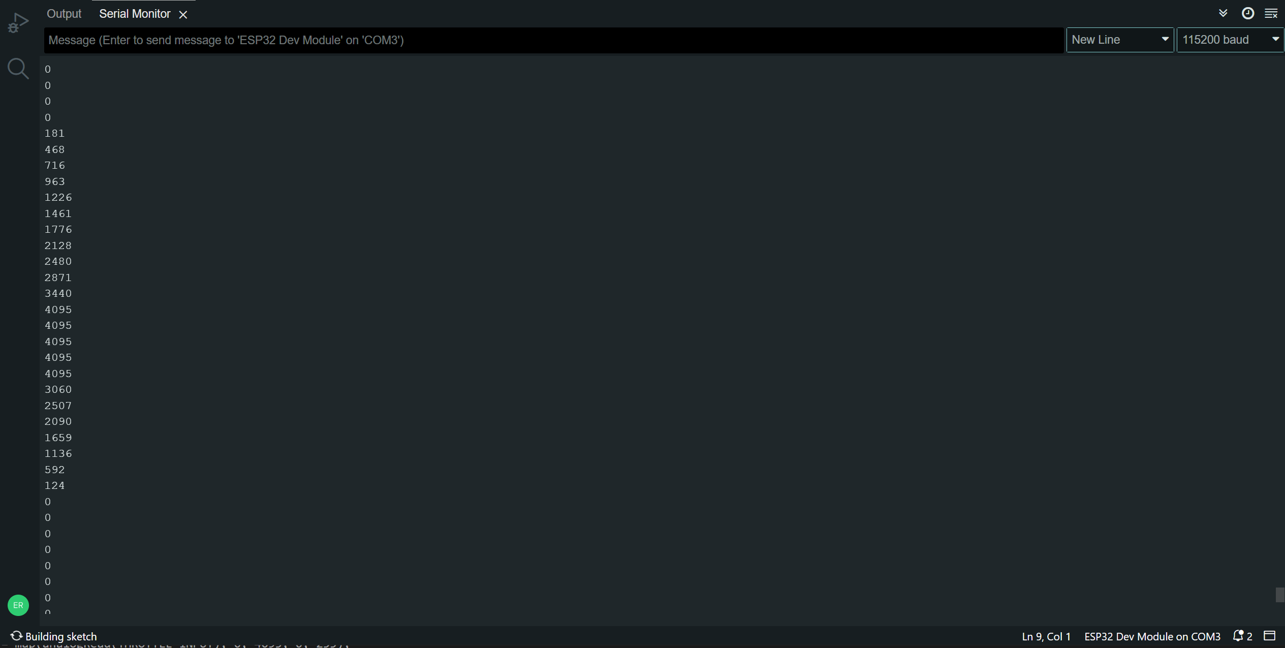
If we simply read the value from the potentiometer, we get the whole range of 12-bit values, which looks like this:
A thing that might not be needed or need to be reinterpreted in order to be useful to control a throttle signal. To map the values obtained onto a 0 to 255 value useful for PWM control we use the "MAP" function in Arduino, code that should look something like this:
	#define THROTTLE_INPUT 12

	int ThrottleReading = 0;
	int Throttle=0;

	void setup() {
		Serial.begin(115200);
		pinMode(12, INPUT);
	}

	void loop() {
		ThrottleReading = analogRead(THROTTLE_INPUT);
		Throttle=map(ThrottleReading, 0, 4095, 0, 255);
		Serial.println(Throttle);
		delay(200);
	}
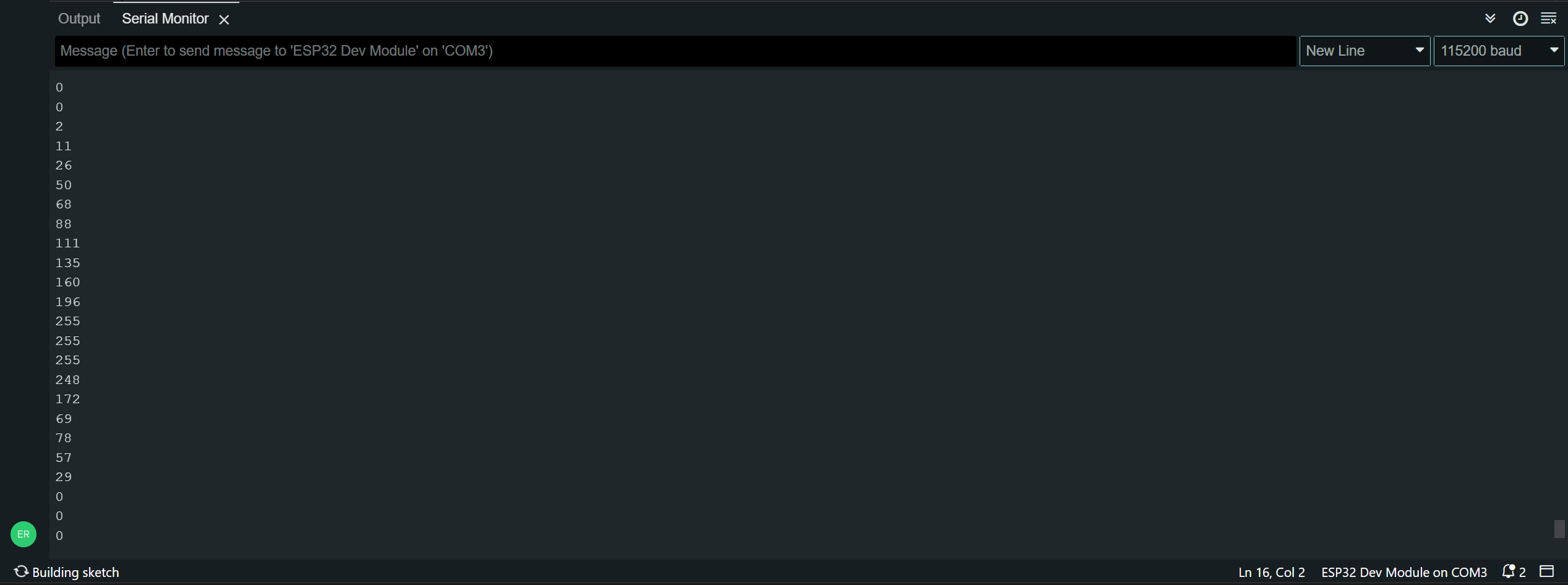
Now, when we turn the potentiometer we will read its position in a value from 0 to 255:
But what if we don't want to read the whole potentiometer's position, but just an angle section? We can reduce the input range on the "map" function, but we need to add an extra step in order to avoid exceeding the 255 value if in a given moment, the analog reading goes a bit beyond the function's limits. The "constrain" function will serve as the value limiter in this example.
	#define THROTTLE_INPUT 12

	int ThrottleReading = 0;
	int Throttle=0;

	void setup() {
		Serial.begin(115200);
		pinMode(12, INPUT);
	}

	void loop() {
		ThrottleReading = analogRead(THROTTLE_INPUT);
		Throttle=map(ThrottleReading, 1000, 2000, 0, 255);
		Throttle=constrain(Throttle, 0, 255);
		Serial.print(ThrottleReading);
		Serial.print(" ");
		Serial.println(Throttle);
		delay(200);
	}
Using this code we can read and translate the potentiometer's position into a throttle signal, and we are also able to limit the input values to a specified range without it overflowing. We can see this in action comparing the raw input (right) and constrained input (left) on the data recieved by the serial terminal. We can see that the constrained data only starts going up when the raw value exceeds the lower map threshold (1000), and stops increasing when the raw reading goes past the upper map threshold (2000). This results in a usable range for my accelerator assembly!
The final reading then, looks like this on the serial port:

Thank you for taking a look into my 11th week's progress!