
9. Output Devices
I this week's assignment I was able to design and fab a simple LED control system for a RaspberryPI-4 board.
High-Level signal control:
At this point we know how to use the inputs and outputs integrated in the microcontrollers we use, we have learned to use them in many creative ways, but what happens if we want to control something that exceeds the electrical capabilities of the microcontroller's pinout?
To control higher-level signals using a smaller one, like the one outputted by a microcontroller, there are many approaches that can be used! Let's put my problem in context: I have a 3D printer whose integrated LED illumination I would like to be able to control it using a 3D printing service webserver running on a RaspberryPI-4. Using the webserver I can control the GPIO on the board, but of course, I need a way to use those signals in order to control the state of a 12V 125mA (1.5W) LED bar.
To do this I devised the following, fairly simple, schematic:
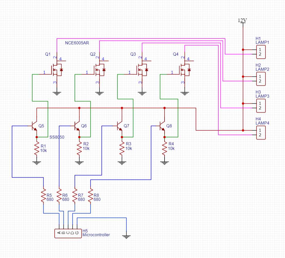
This circuit makes use of four P-Channel MOSFET transistors, which allow to control higher voltage and current levels with a very small signal. Underneath them there are another four NPN BJT transistors, which serve as drivers for the larger MOSFETS. R1, R2, R3 and R4 are current-limiting resistors for the BJT driver transistors, pick a value too small, and too much current will flow through the BJT transistor, heating it up unnecessarily or straight down burning it. Alternatively, choose a value too high and very little current will flow, to the point it doesn't reach the minimum conducting current needed to activate the transistor. Using the 10K resistors, a current of 0.0012A (1.2mA) will flow through the transistor, creating a voltage between it's emitter and the resistor, voltage which sequentially, activates the MOSFET transistor. There are also four extra resistors: R5, R6, R7 and R8, which serve the purpose of limiting the current drawn from the control signal of the microcontroller into the base of the BJT transistor. Choosing values too low or too high could lead to a GPIO overload or a poorly saturated transistor.
MOSFET's like the ones used, cannot be controlled directly by the GPIO of the microcontroller, as their control signal must be near the supply voltage they will be controlling. Why bothering then with a MOSFET based circuit, if BJT can do the same thing and be directly controlled?
Well, I chose that approach for one main reason: Power Efficiency. BJT's tend to have higher energy losses proportional to the power they are letting pass through them, meaning that a given power draw, BJT's tend to get hotter and dissipate more energy from the system than MOSFET's. BJT's are still used in this case, but the role they fill as drivers means that a lot less power flows through them, and consequentially, less power is wasted as heat. The real load will be handled by the MOSFET's.
Each BJT - MOSFET combo drives a single LED lamp up to the MOSFET's maximum power rating, in this case I used the NCE6005 MOSFET, which has a power rating of 2W. I added four channels in case I wanted to control 4 lights simultaneously.
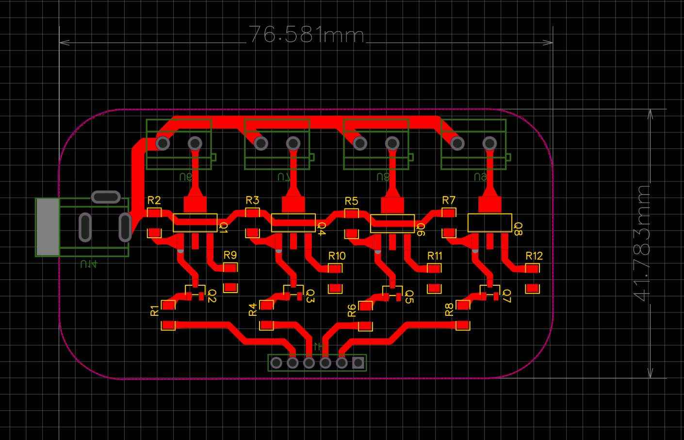
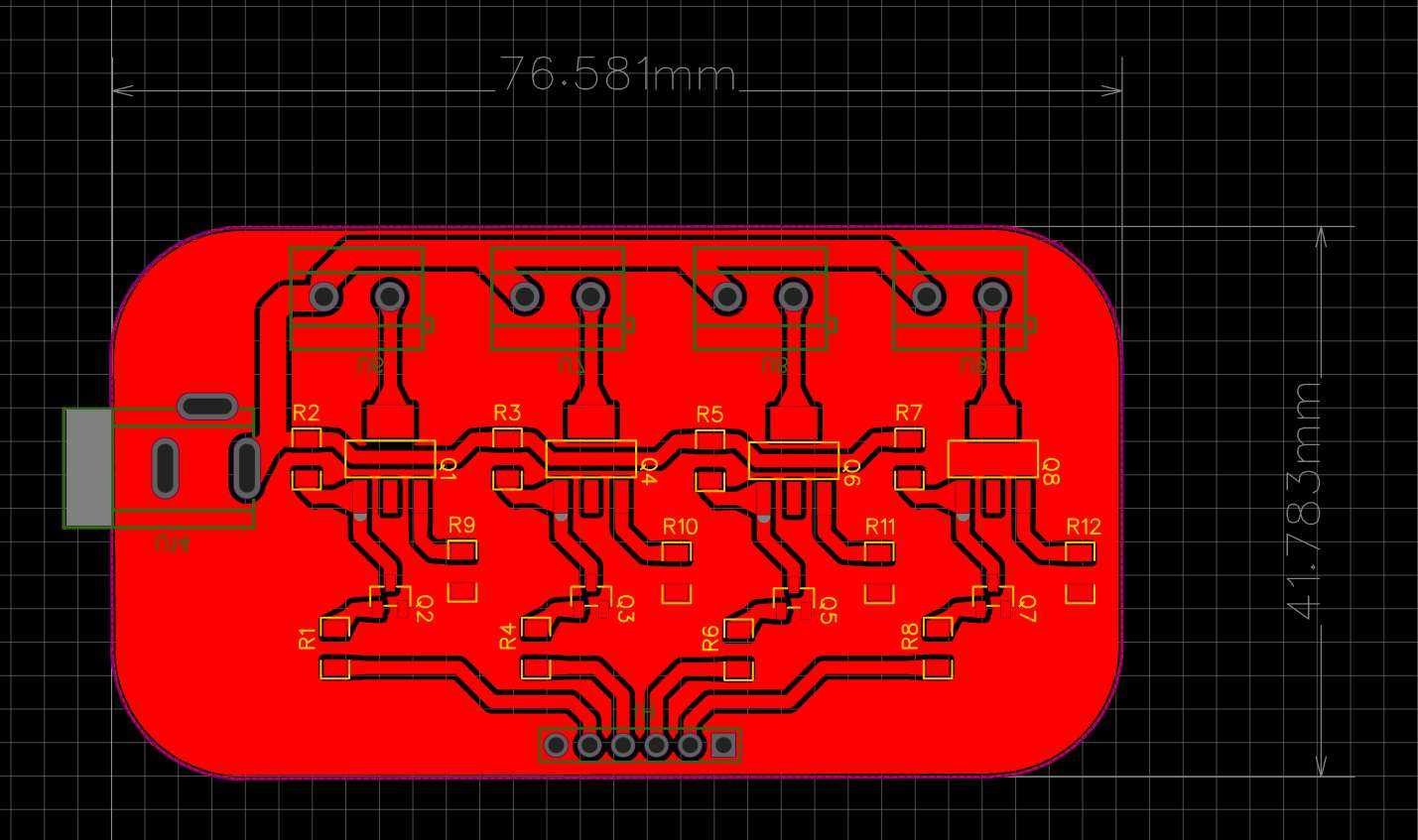
Designing the PCB:
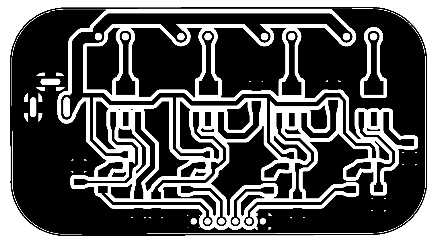
I again used EasyEDA to design my PCB, the power traces are this time a little wider, as they will be carrying more current to feed all the connected lamps. Except for the pin headers, the screw terminals and the DC barrel jack, every component is meant to be sufrace mounted.
Once every trace was made, I added teardrops to every pad in order to create stronger connections when fabbing the board, also, I like to include a general ground plane using the empty spaces of the board, this makes connecting grounds easier and reduces unwanted noise in the circuit; and because there's less material to remove, board milling is faster!
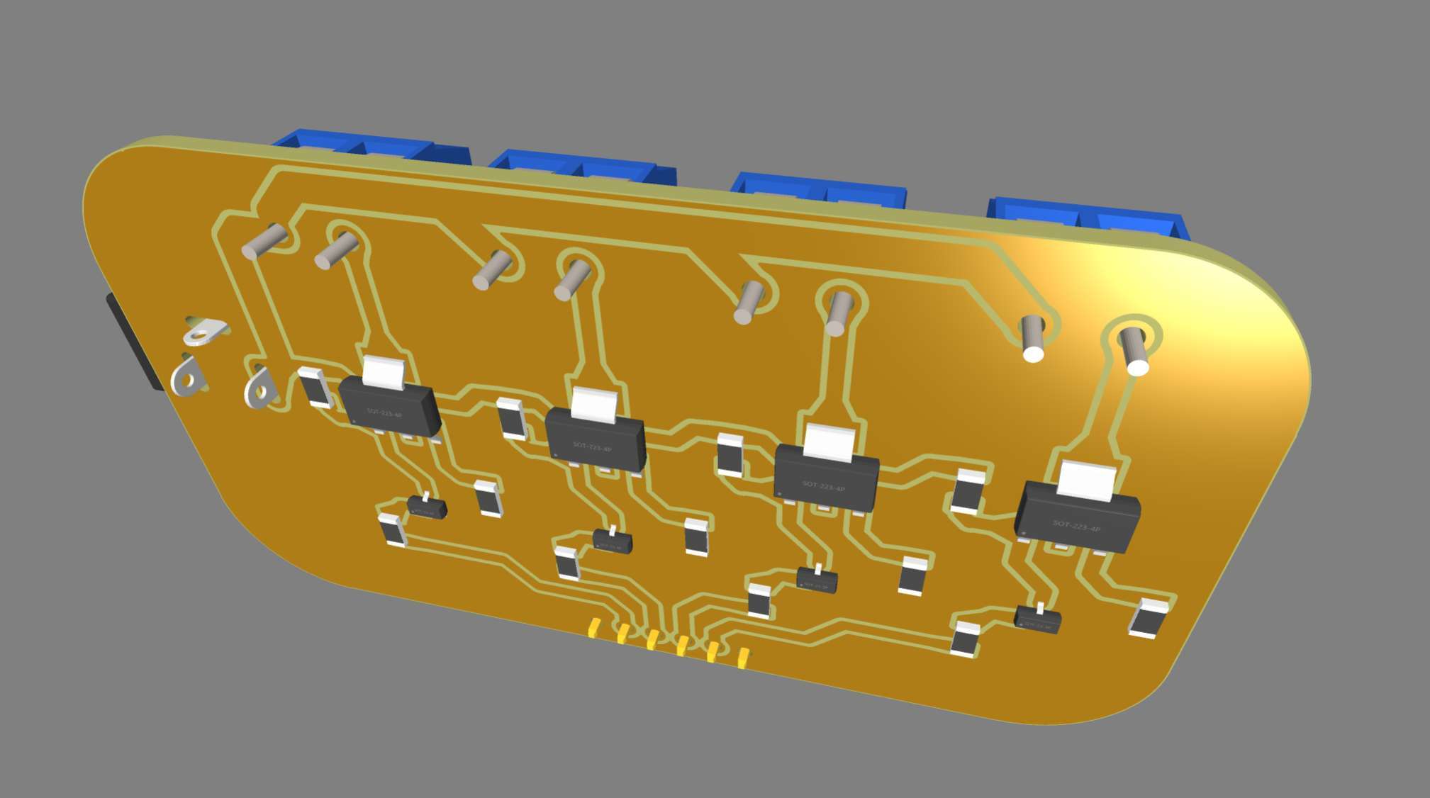
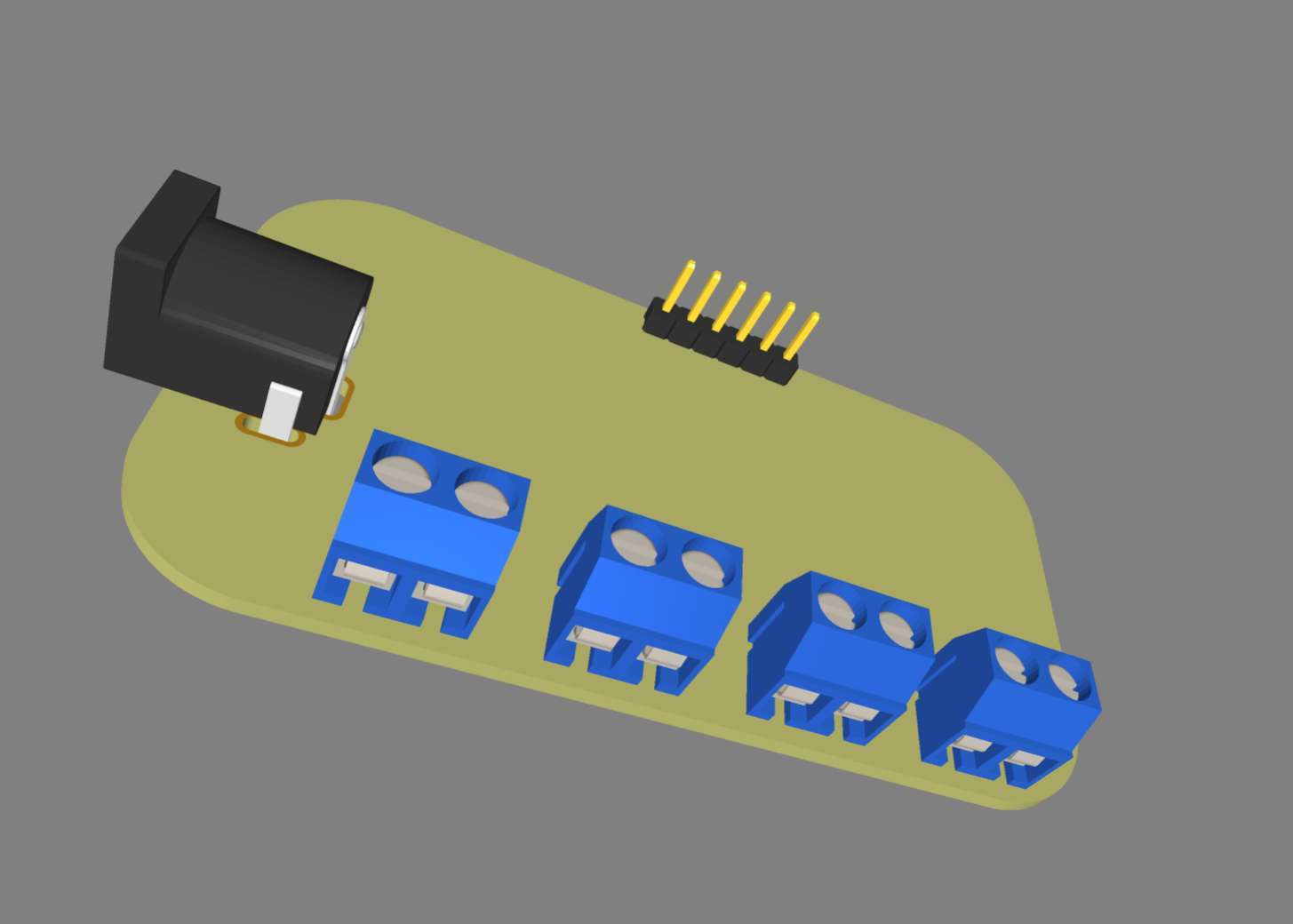
Once finished and using the incorporated 3D viewing tool, we can see how the board should look like once assembled:
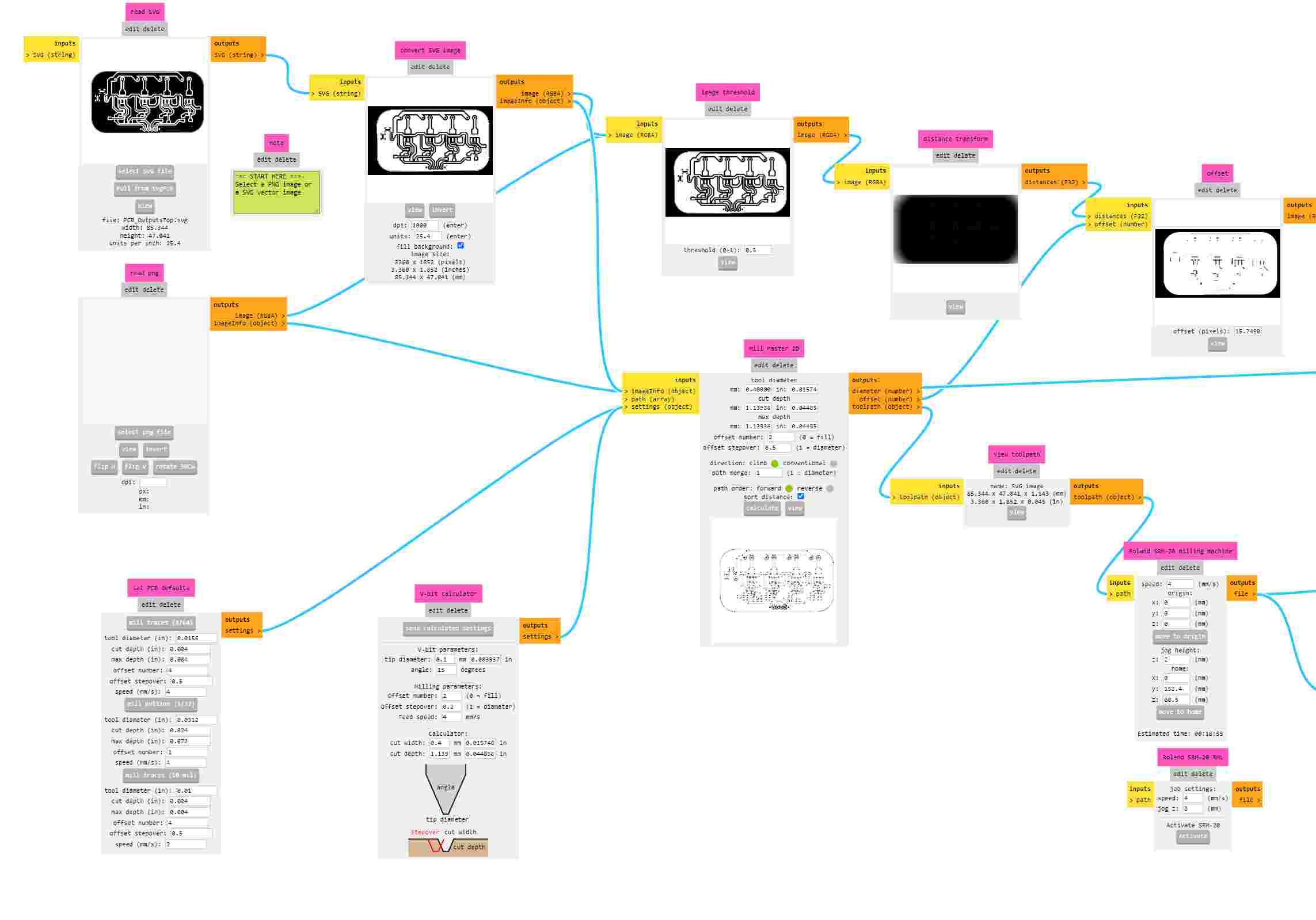
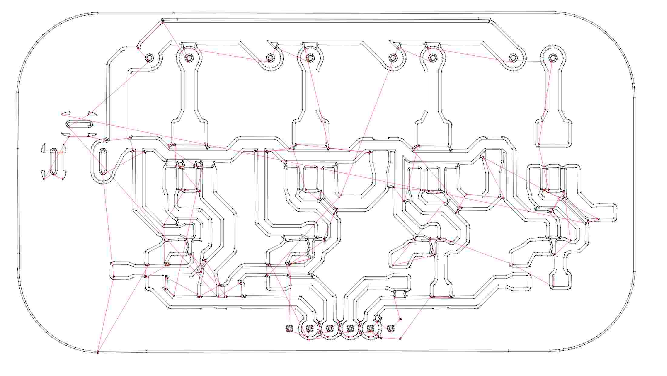
Now that the board is designed, I exported it in SVG format, and imported it in MODS to create its milling gcode. We're using the Roland Monofab machine, so I chose its respective profile in MODS proyect.
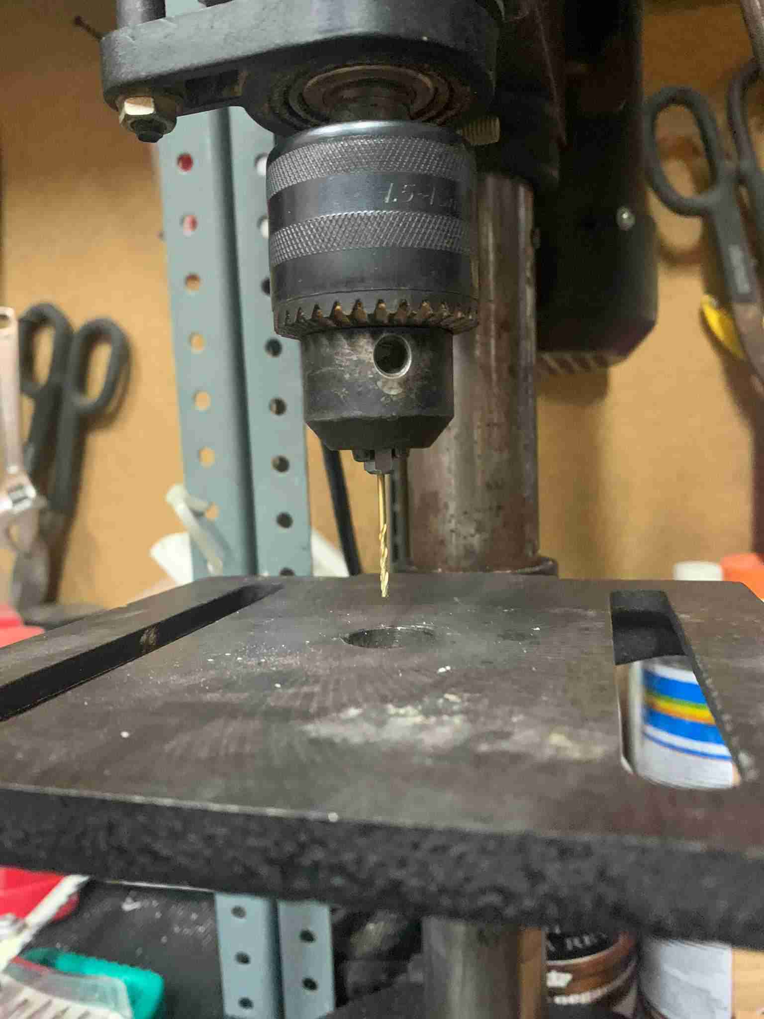
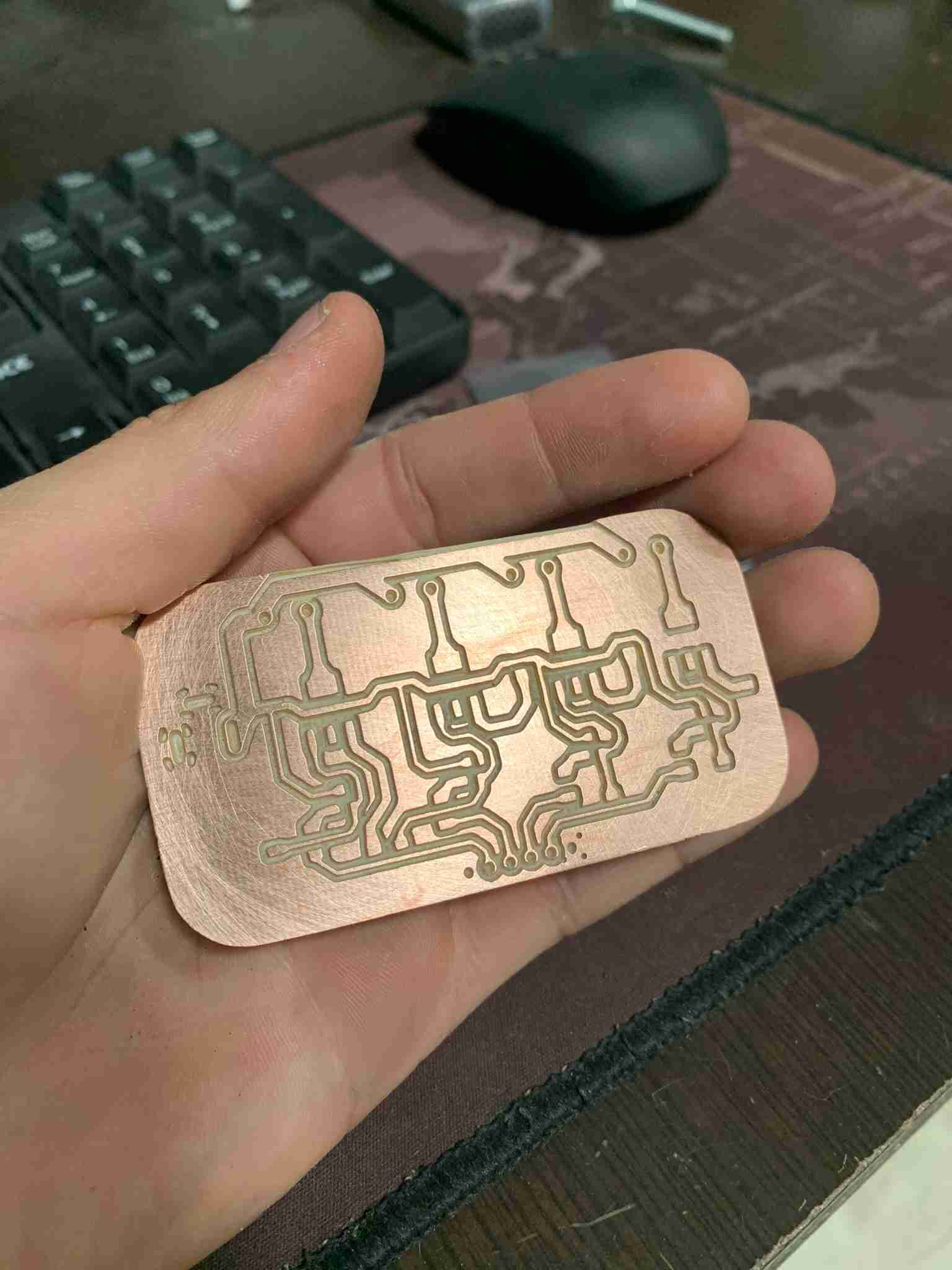
For some reason, I wasn't able to figure out, I could't cut the outline of the PCB on the Milling Machine, so I drilled and sawed the outline and holes manually. Not very difficult though with the right tools. I used a small precision saw and a bench drill with a 1/32" drill bit. I then sanded the surface using a 120 grit sandpaper with a sponge. This left a very smooth and shiny surface that is easy to solder on.
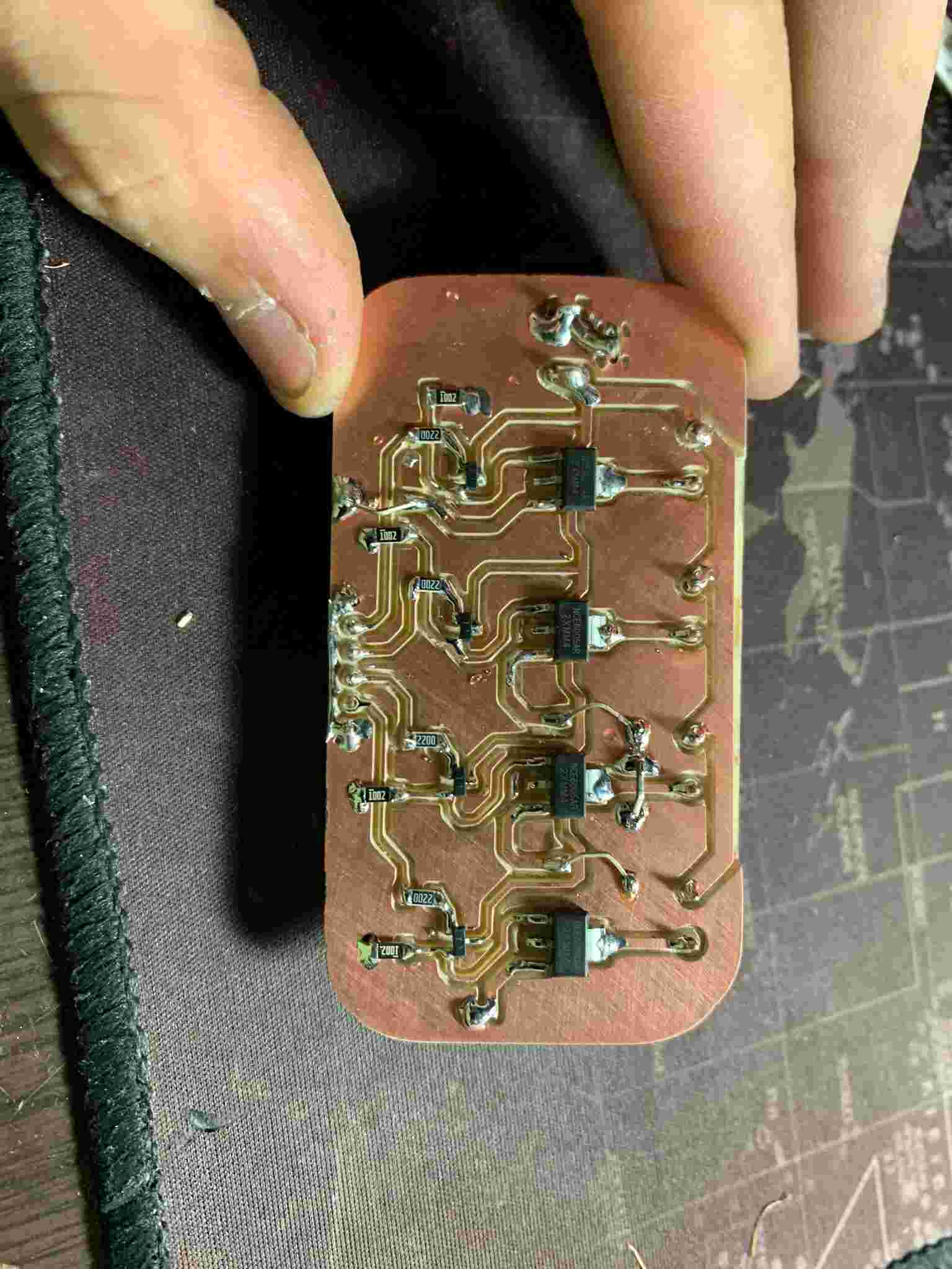
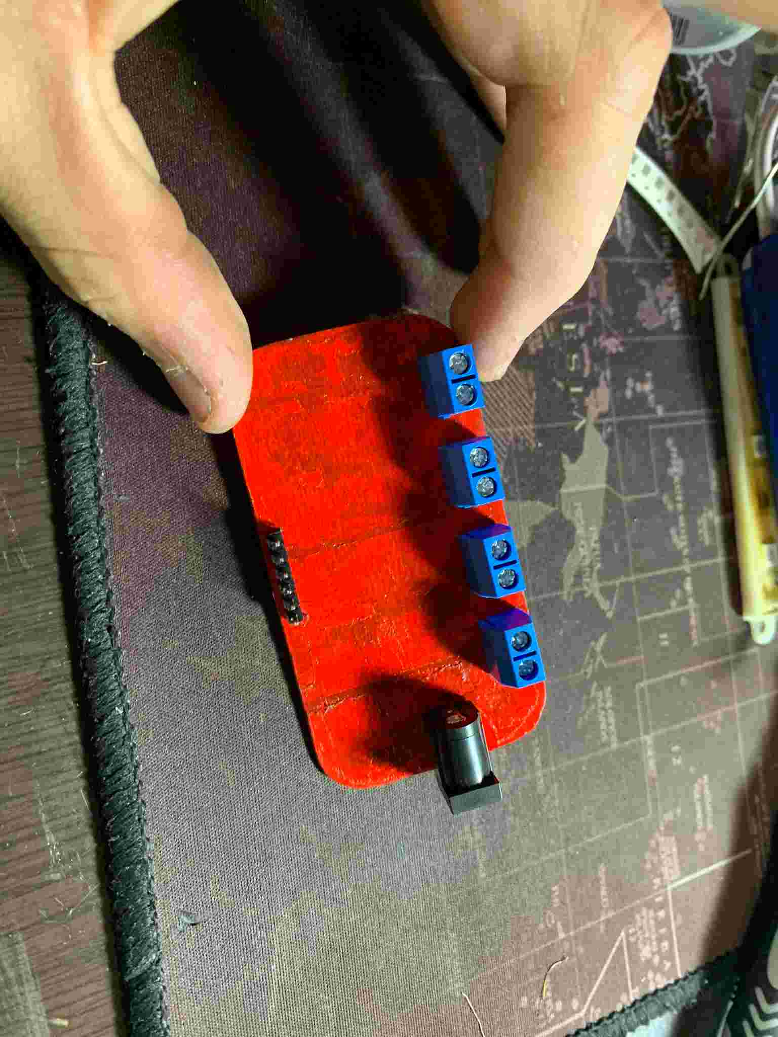
Then, using a soldering iron heated to 250°C, I started soldering all of my components, starting with the resistors, followed by the MOSFET's and BJT drivers and finishing with the through hole components and two wire bridges. I wanted to use so-called, zero ohm resistors to do this, but I couldn't find them for sale. As the board's reverse was for some reason stained and sticky, I painted it red, because it was the only paint color I had available at the moment, it resulted in a nice contrast with the blue screw terminals.
To test the circuit I used four 12V red LED strips, a 12V power brick and an Arduino UNO to send the test signals. I connected the LED's accordingly and uploaded the following code to the arduino:
#include Adafruit_NeoPixel.h  // Include the Adafruit NeoPixel library
#ifdef __AVR__
#include avr/power.h // Required for 16 MHz Adafruit Trinket, include AVR power library
#endif

// Define which pin on the Arduino is connected to the NeoPixels
#define PIN        D5 // Suggested change for Trinket or Gemma to pin 1

// Define the number of NeoPixels attached to the Arduino
#define NUMPIXELS 64 // Size for a popular NeoPixel ring

// Initialize the NeoPixel strip on the specified pin, with the specified number of pixels
Adafruit_NeoPixel pixels(NUMPIXELS, PIN, NEO_GRB + NEO_KHZ800);

#define DELAYVAL 100 // Delay time (in milliseconds) between updates to the pixels

void setup() {
// These lines are for the Adafruit Trinket 5V 16 MHz.
// They set the clock prescaler to ensure the microcontroller operates at the correct speed.
#if defined(__AVR_ATtiny85__) && (F_CPU == 16000000)
clock_prescale_set(clock_div_1);
#endif
// This is where the Trinket-specific code ends.

pixels.begin(); // Initialize the NeoPixel strip object. This is required to start controlling the LEDs.
}

void loop() {
pixels.clear(); // Turn all LEDs off to start with a clean state.

// Loop over each pixel in the strip (from 0 to NUMPIXELS-1)
for(int i=0; i<=NUMPIXELS; i++) {
	// Set the color of the current pixel to a moderately bright green.
	// The Color method takes three arguments: red, green, and blue intensity (from 0 to 255).
	pixels.setPixelColor(i, pixels.Color(0, 150, 0));

	pixels.show();   // Apply the color changes to the strip. This makes the update visible.

	delay(DELAYVAL); // Wait for a bit before moving on to the next pixel.
}
}
And as you can see in the following videos, it inmediately worked! Using PWM on the selected GPIO, you can also vary the LED's brightness.
Thank you for following me into my 9th week's progress!