
7. Computer Controlled Machining
I this week's assignment I was able to design, machine, and build a very interesting woodworking proyect!
Tensegrity Structures:
Since I had heard of them, tensegrity structures have always caught my attention, as they seem to defy logic and the laws of physics themselves: How on earth does a bunch of wire hold a structure under compression? Well, once everything is explained, it all makes sense and gets a lot less glamorous.
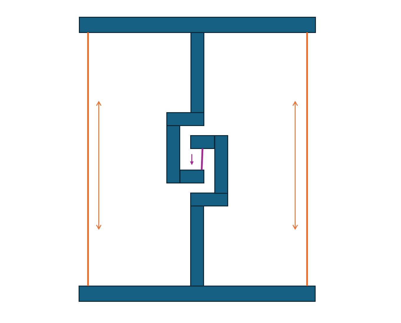
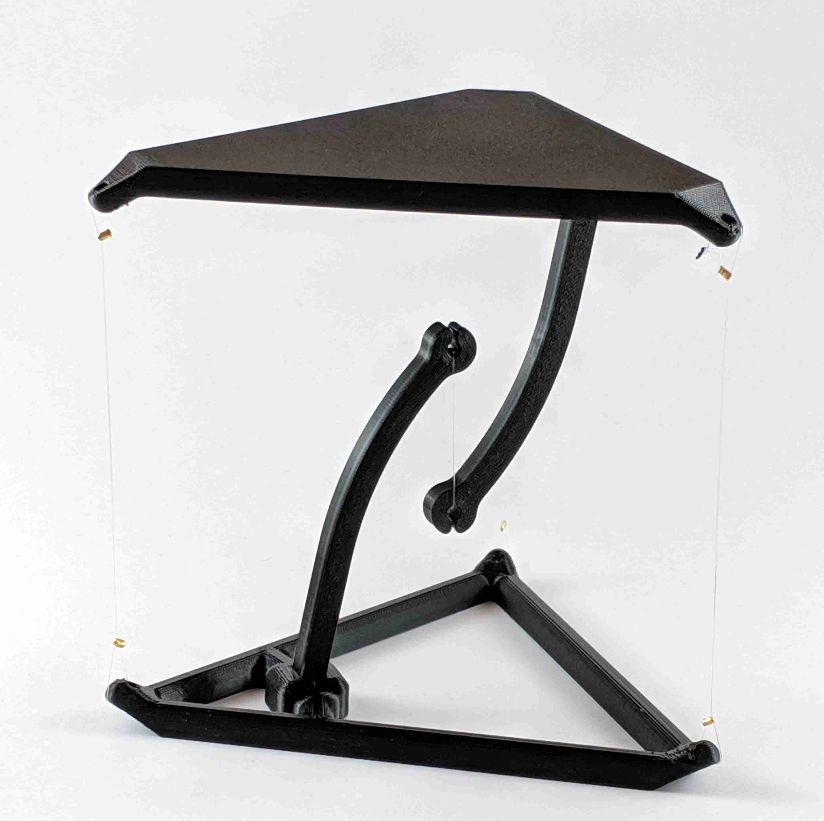
As you probably know, a piece of rope or wire doesn't like compression forces too much, but excels when submitted to tension. Tensegrity structures are then stable systems that rely on cables in tension to hold it's own weight, but where rigid components never touch each other; understanding the direction of forces thus becomes very important when designing one of this structures, to assure every cable present is in tension and can hold the weight placed on it. The following diagram shows the direction of forces in the table I intend to design, as you can see, the purple wire holds all the weight of the table and of the eventual things you put on top, this while the orange wires hold the table in place, preventing it from collapsing onto its sides. On the left image you can see the same concept on a small scale, as advertised in a product from Etsy.
If we use thin wires that are strong enough to hold its load, the table should create the illusion of it floating!
Designing the table's pieces:
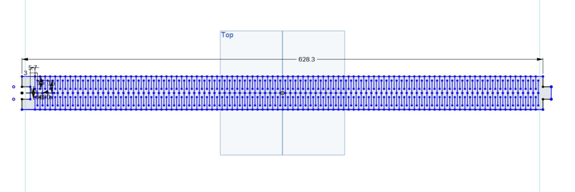
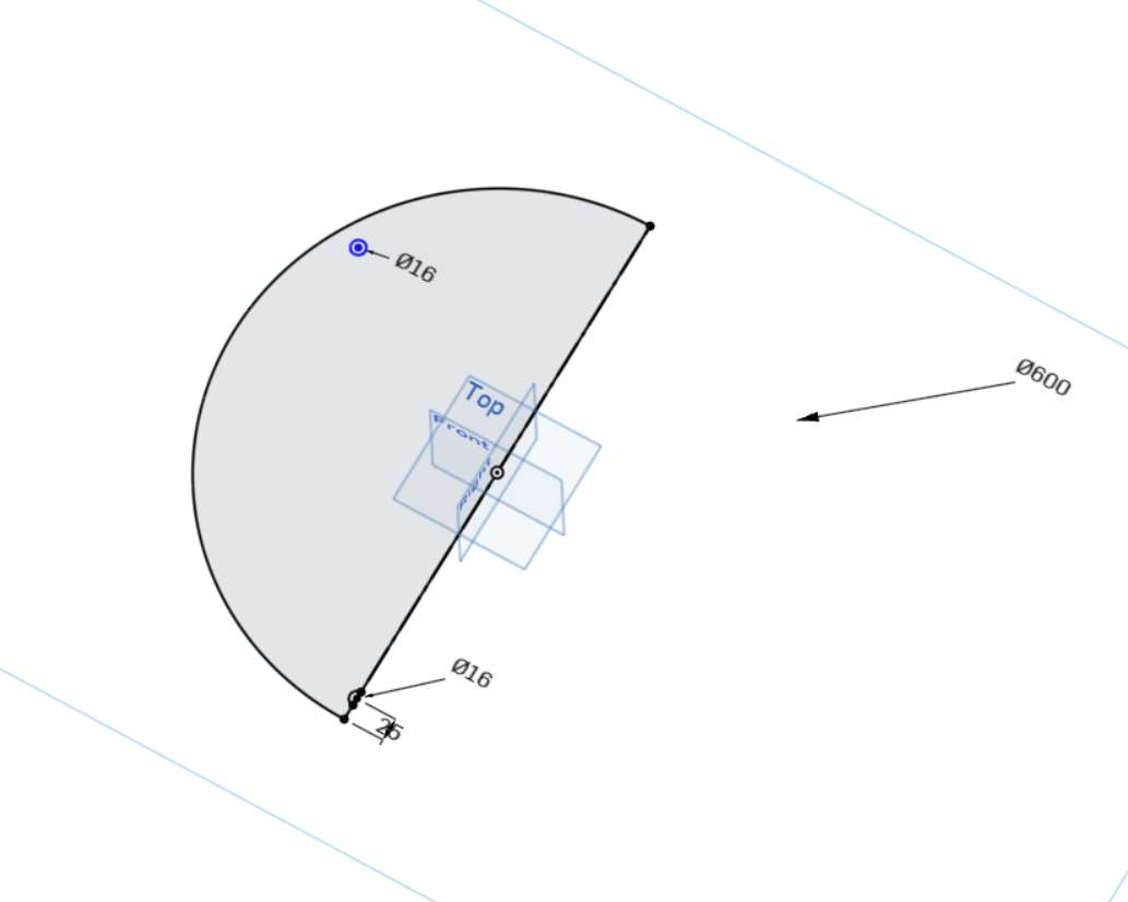
I again used OnShape to create the fairly simple pieces that would compose my creation, that unlike the model from Etsy, I wanted my table to be real-sized and actually useful, beyond just a novelty product. The designs for the two main pieces are shown below:


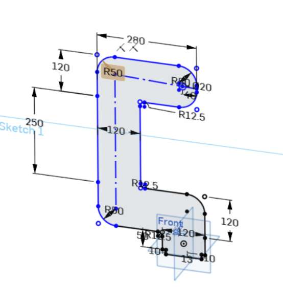
The table is made from two identical opposing assemblies, an arm and one table make one of the assemblies.
Once the design was ready, I exported the sketches in .dxf format for the CNC machining process.
Preparing the files for CNC machining:
I had never used a CNC router before, thus almost everything about it is new to me, and it is quite different from other computer controlled manufacturing processes such as laser cutting.
The first thing to do is to import the .dxf files into the CNC routing software, which in our case is V-Carve.
Inside V-Carve we can convert the .dxf file into G-Code the router can work with, while carrying all the machine's important parameters such as the spindle rotational speed, the feed speed (how fast the tool makes its path through the material), and the tool's diameter.
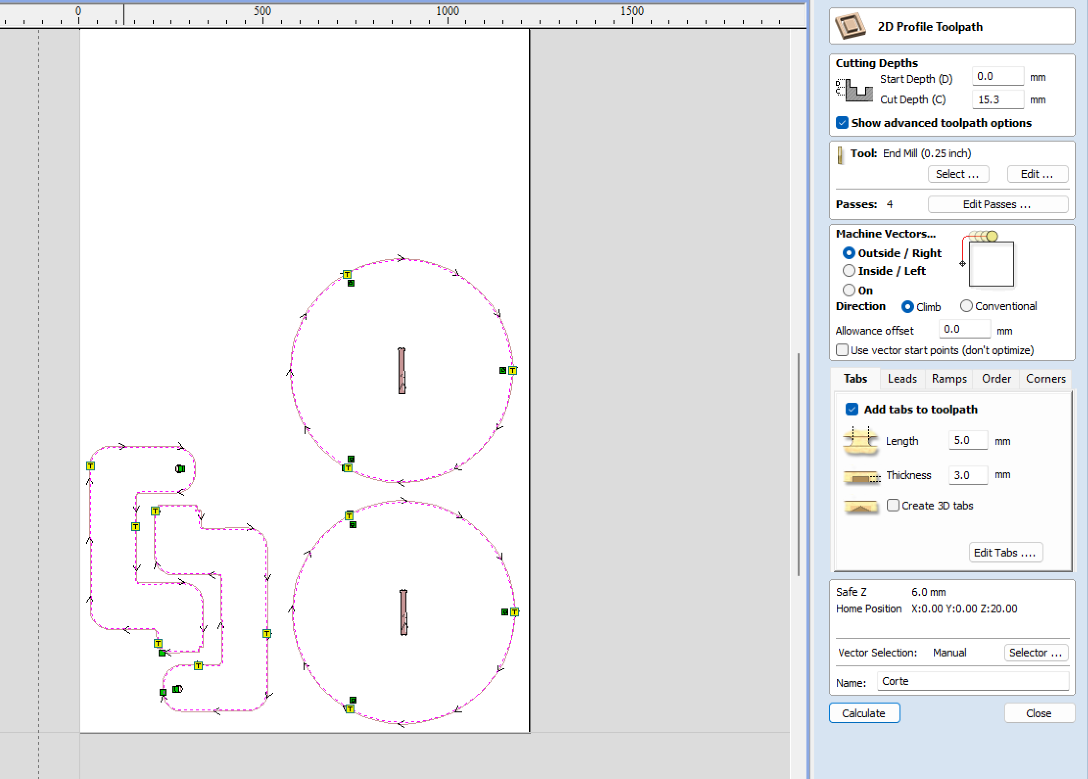
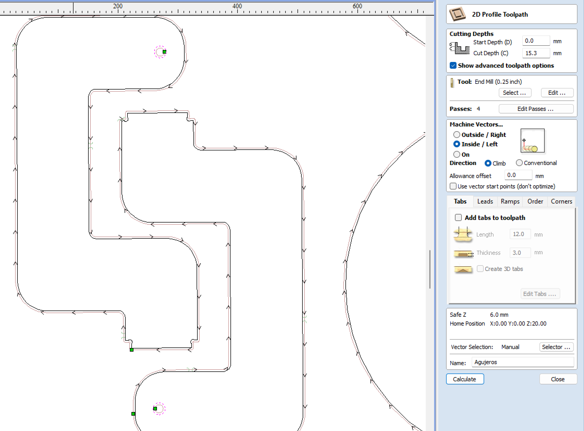
The nature of the paths also has to be defined: In which lines do you want the router to cut through the whole material? And, in which lines should it only carve up to a certain depth? You can choose how the tool will behave as well: The tool is certainly much bigger than the precision point made by a laser, so making the tool pass exactly over the cutting line may not be the best choice. In V-Carve you can choose between the latter, and the tool following the inside or the outside of the cutting lines by a margin equal to that of the tool's diameter, so that, at least in theory, there's no kerf to consider.
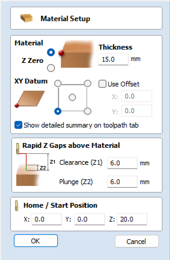
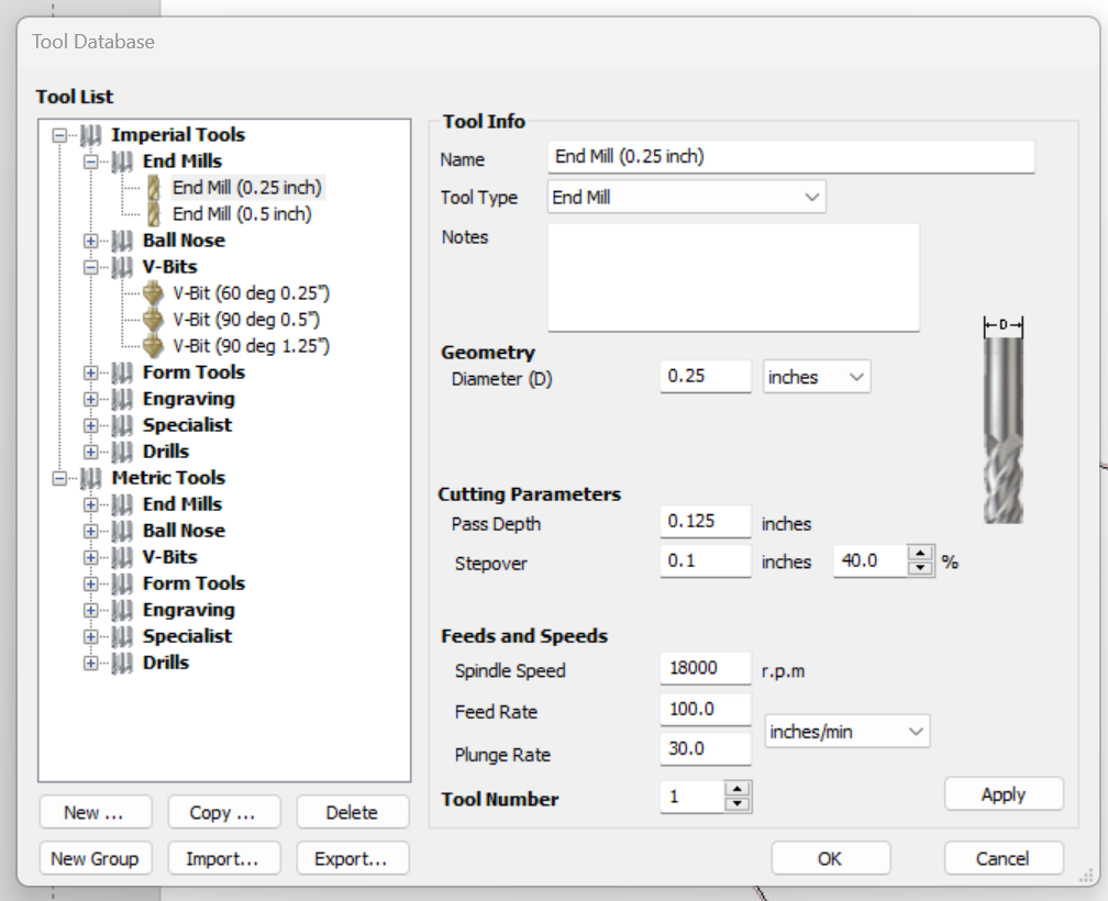
Within V-Carve I configured the material we were using, which in this case was a 15mm MDF board. In this stage I also configured the tool that I used, which was a 1/4" tungsten carbide end mill, which according to the info provided in our group assignment's webpage, I configured to a spindle speed of 18,000 RPM and a feed rate of 100 IPS.
After that, I imported the DXF files of my designs, which I then arranged inside the work area to optimize some space and waste the least material possible.
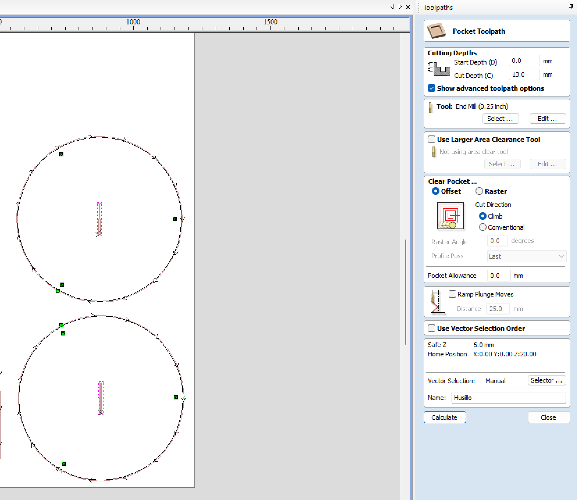
Then, I configured every toolpath for the machine, the outer cutting paths were left as external routings, where the tool follows the path on the outside. Things like holes and such were left on the inside. The slots for the dogbone assemblies were configured so the tool only got through 12 of the 15mm the board has in thickness.
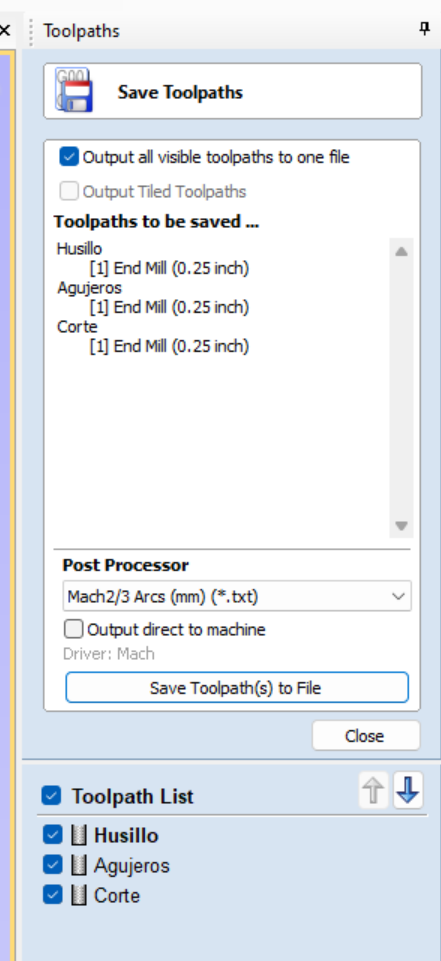
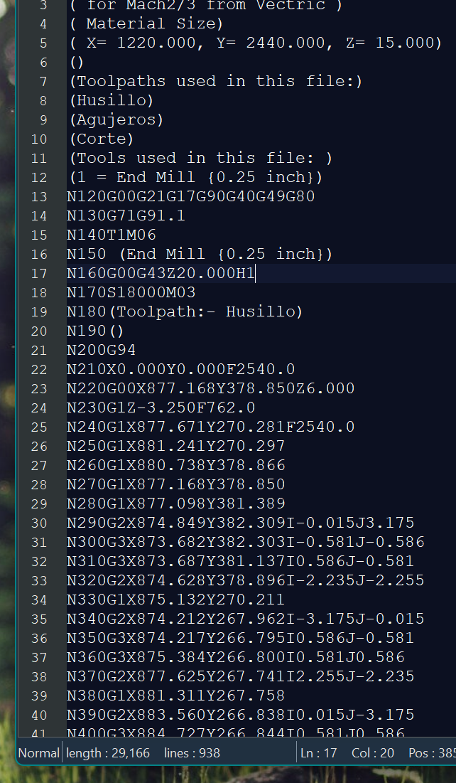
After everything was looking good, I exported the G-Code to a text file to be sent to the CNC machine. To do this, we look for the "save toolpath menu" and select the postprocessor corresponding to our machine, in my case, it was Mach 2/3 Arcs. After all is done, you will obtain a .txt file that contains all your design's cut profiles and parameters, this G-Code must then be uploaded to the CNC router.
Using the CNC Router!:
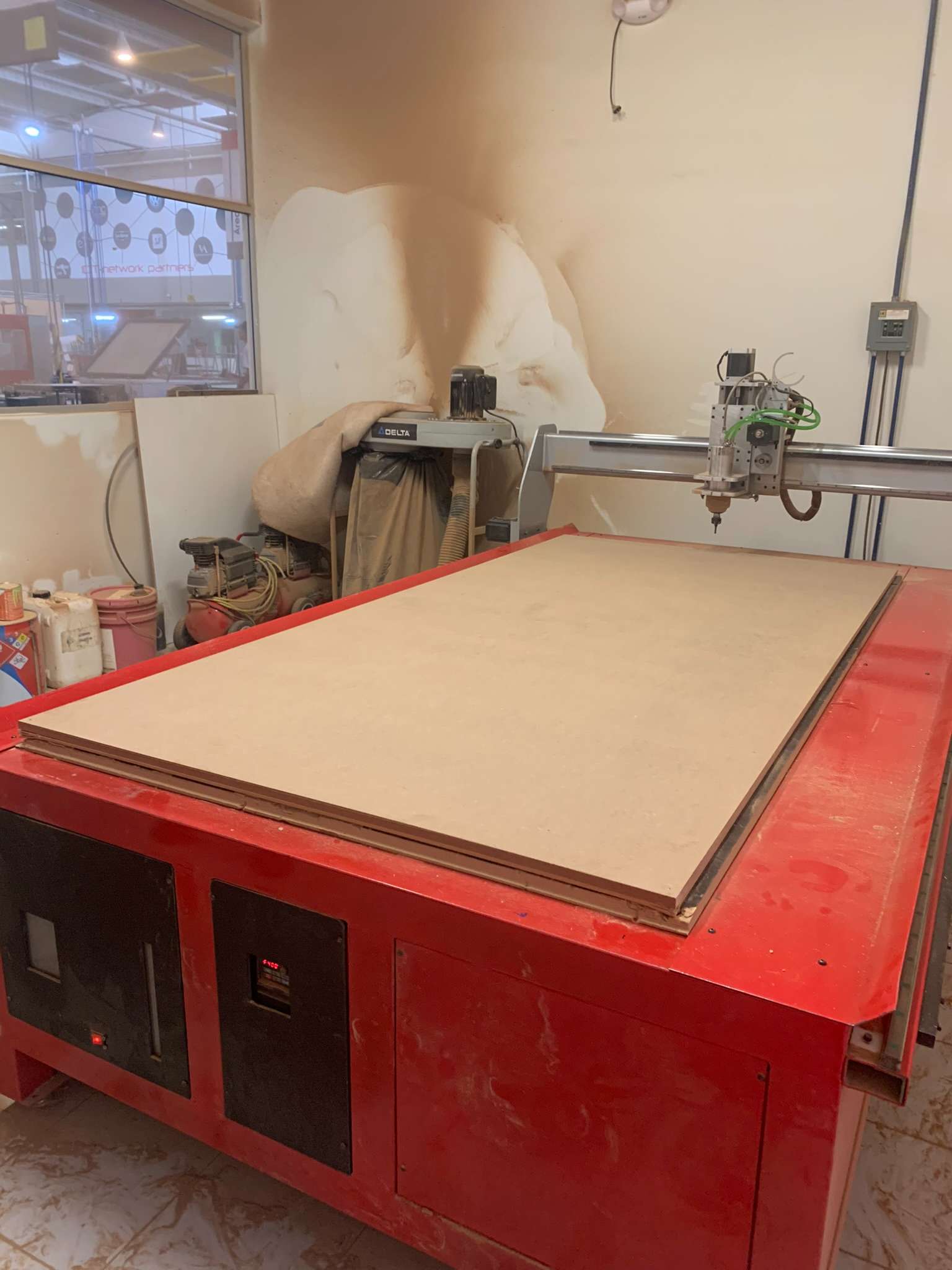
In our FABLAB we have a pair of CNC routers that fill each an entire room, and using them requires you to follow a list of safety measures. A lab coat, safety glasses, safety boots, and a N95 respirator is the required protection equipment to enter the machining room.
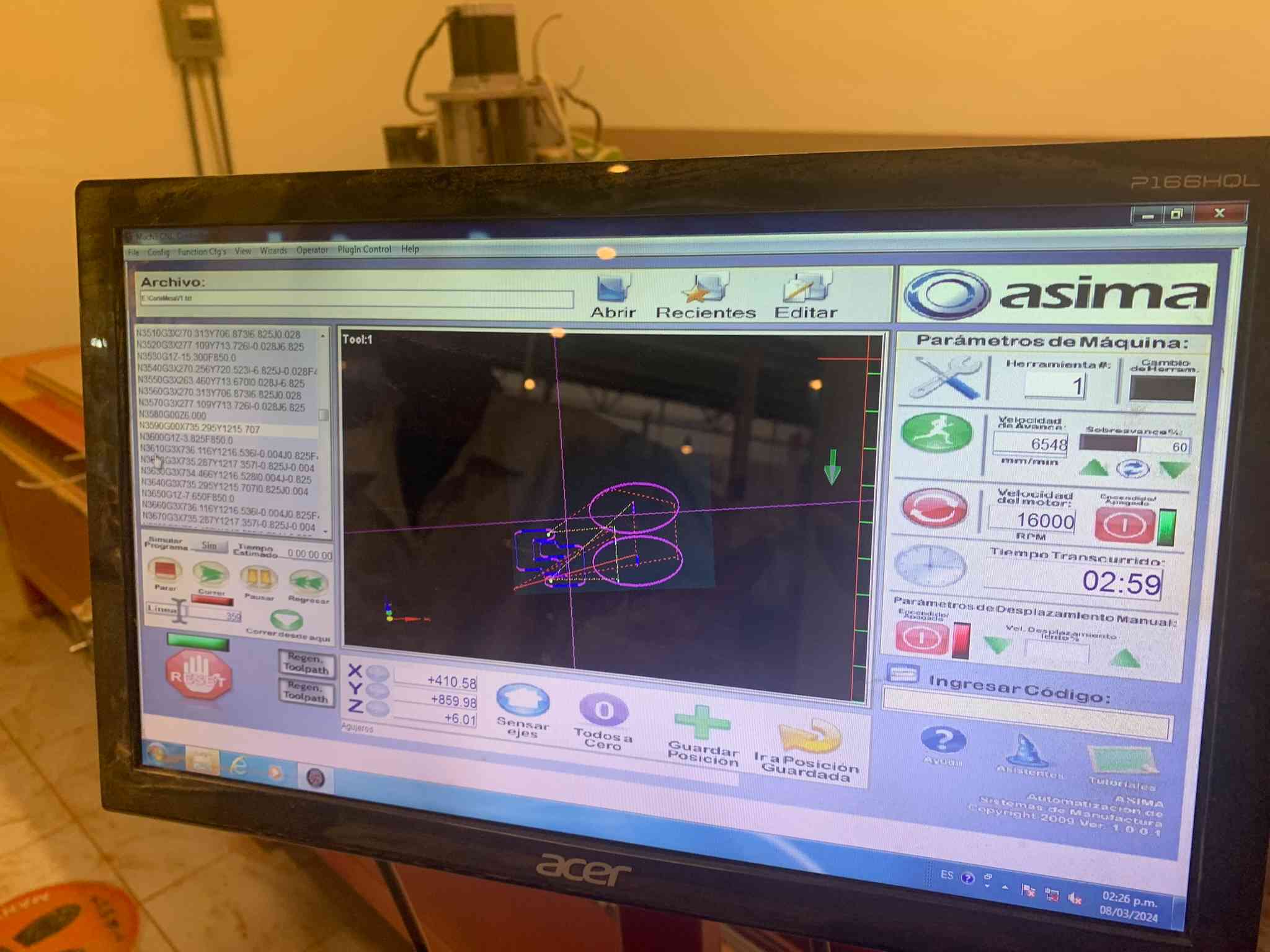
These routers have a dedicated computer to control them: Using the keyboard's arrow keys we can move both the X or Y axes, and with the PG UP and PG DOWN keys, we can lower or raise the tool along the Z axis. Using those controls we move the machining head up to the point we want our origin to be. Using a USB thumbdrive we can get our G-Code onto the machine via the dedicated computer and software.
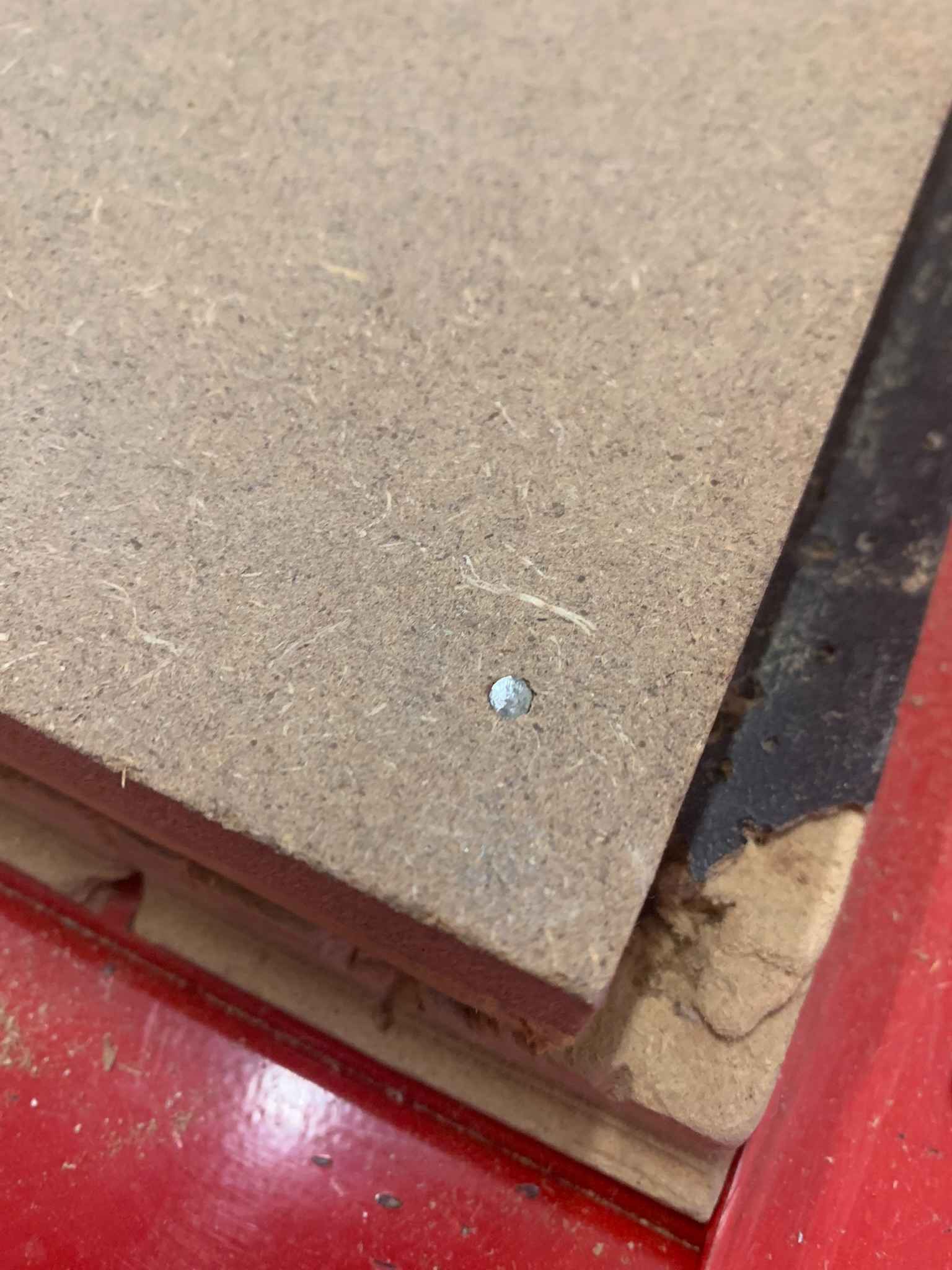
The material to machine, in this case a 220 cm x 122 cm x 15mm MDF board, has to be fastened onto the cutting bed using nails or other reliable fastening method. This time we used 4 nails to fasten the board, one in every corner.
The machining process took about 15 minutes, and left behind a lot of sawdust which had to be removed using an aspirator with a particle filter:
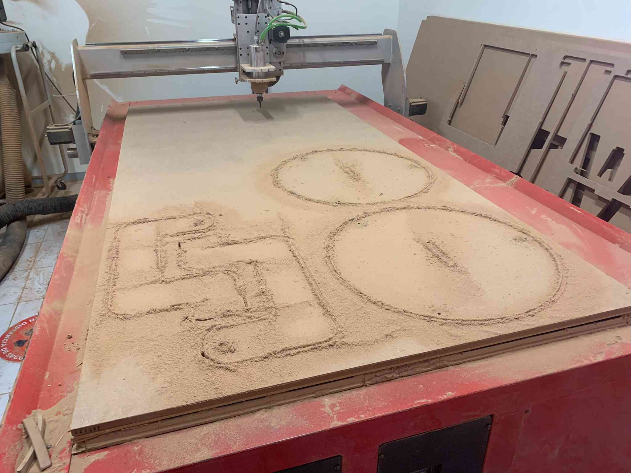
Once the sawdust is removed, the pieces can be easily removed from the board!
Assembly:
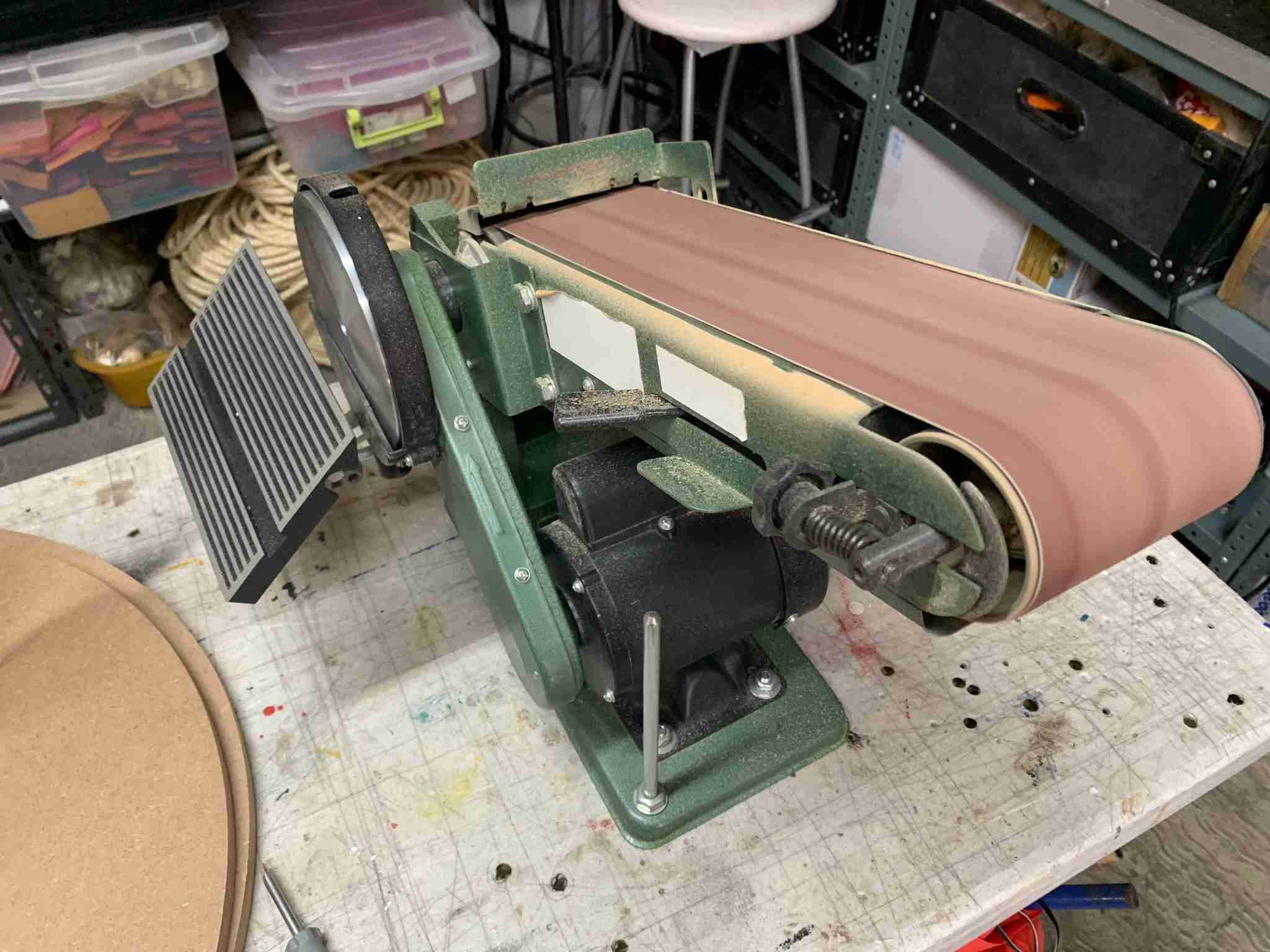
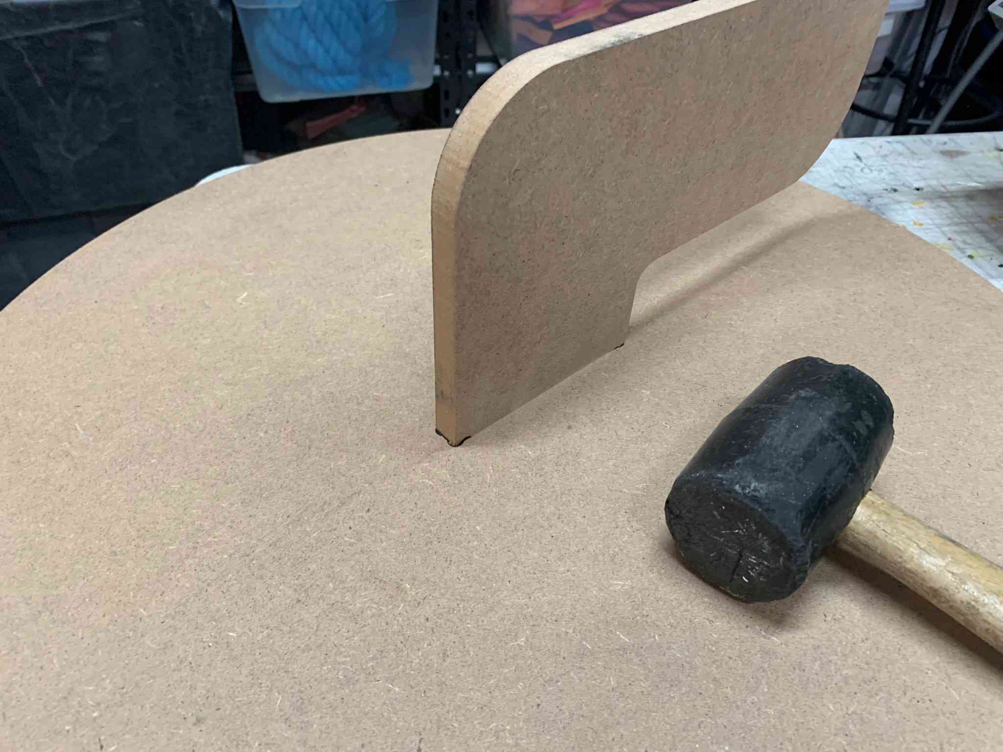
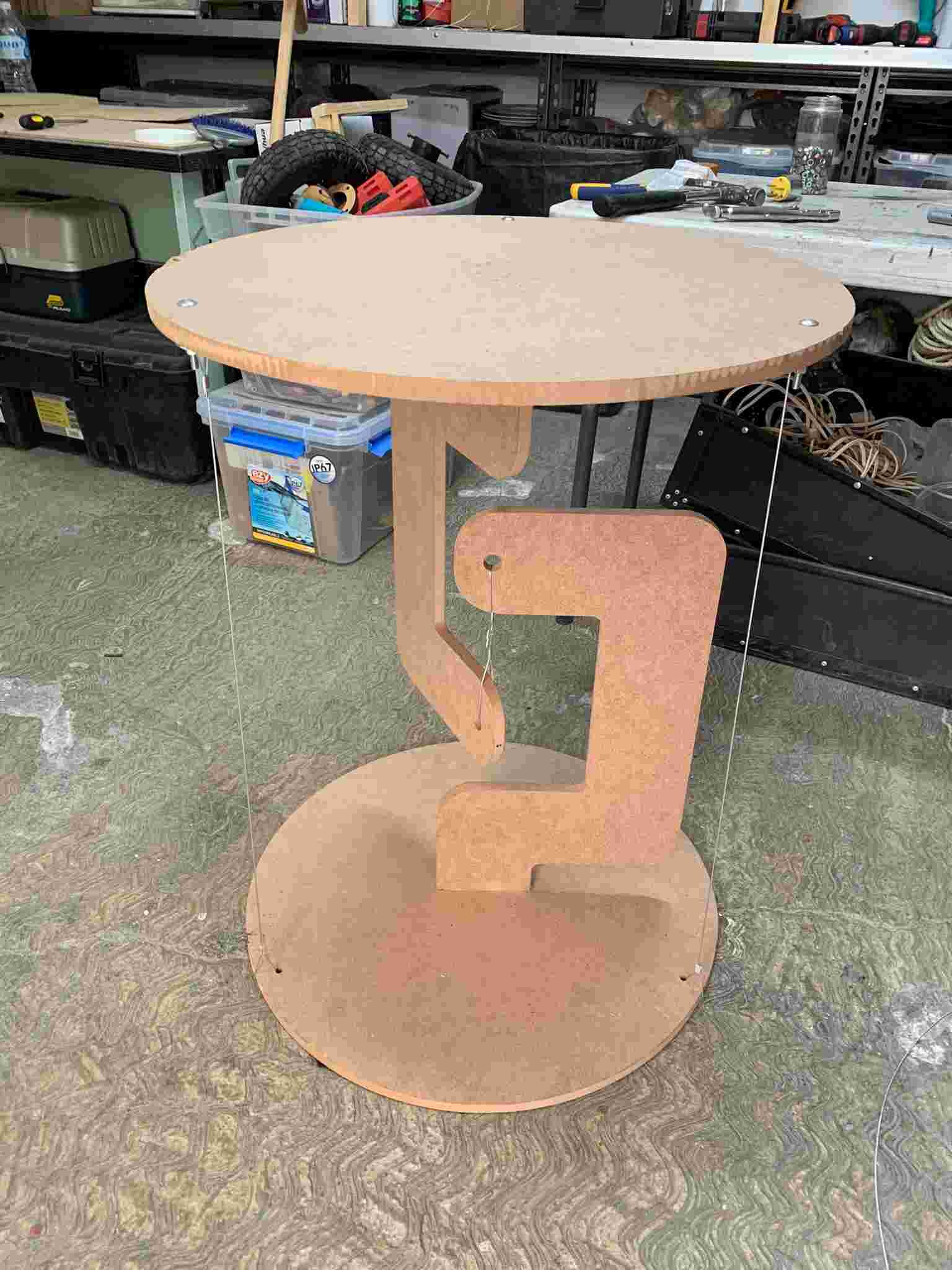
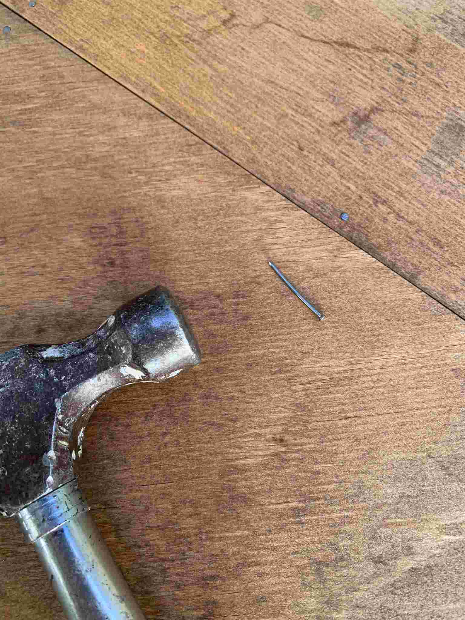
Using a rubber hammer, I pressed the arm and table pieces together, the press fitting was achieved without any glue using a dogbone pattern and a bit of sanding with a belt sander:
This assembly was repeated twice to obtain the two main parts of the table.
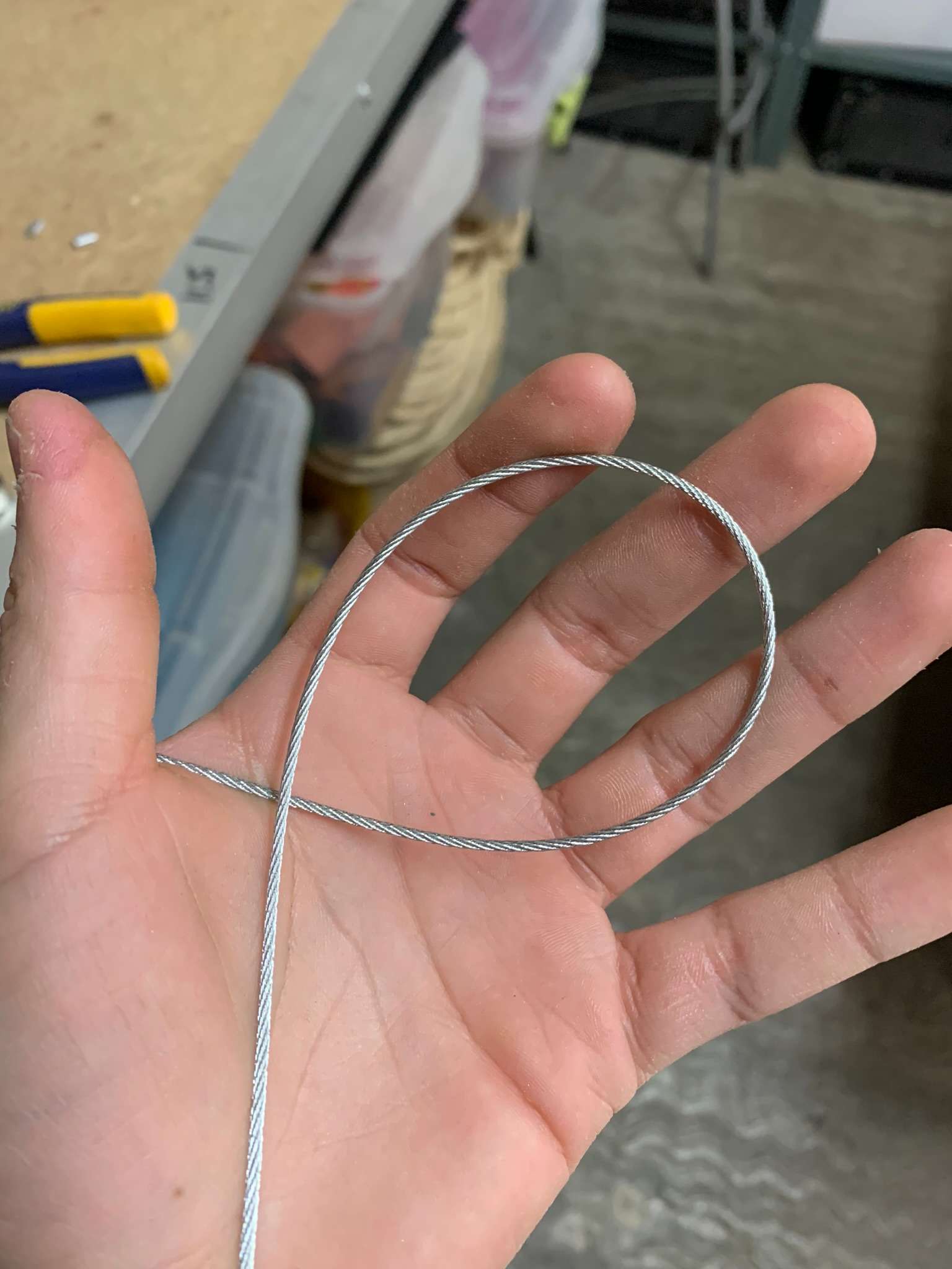
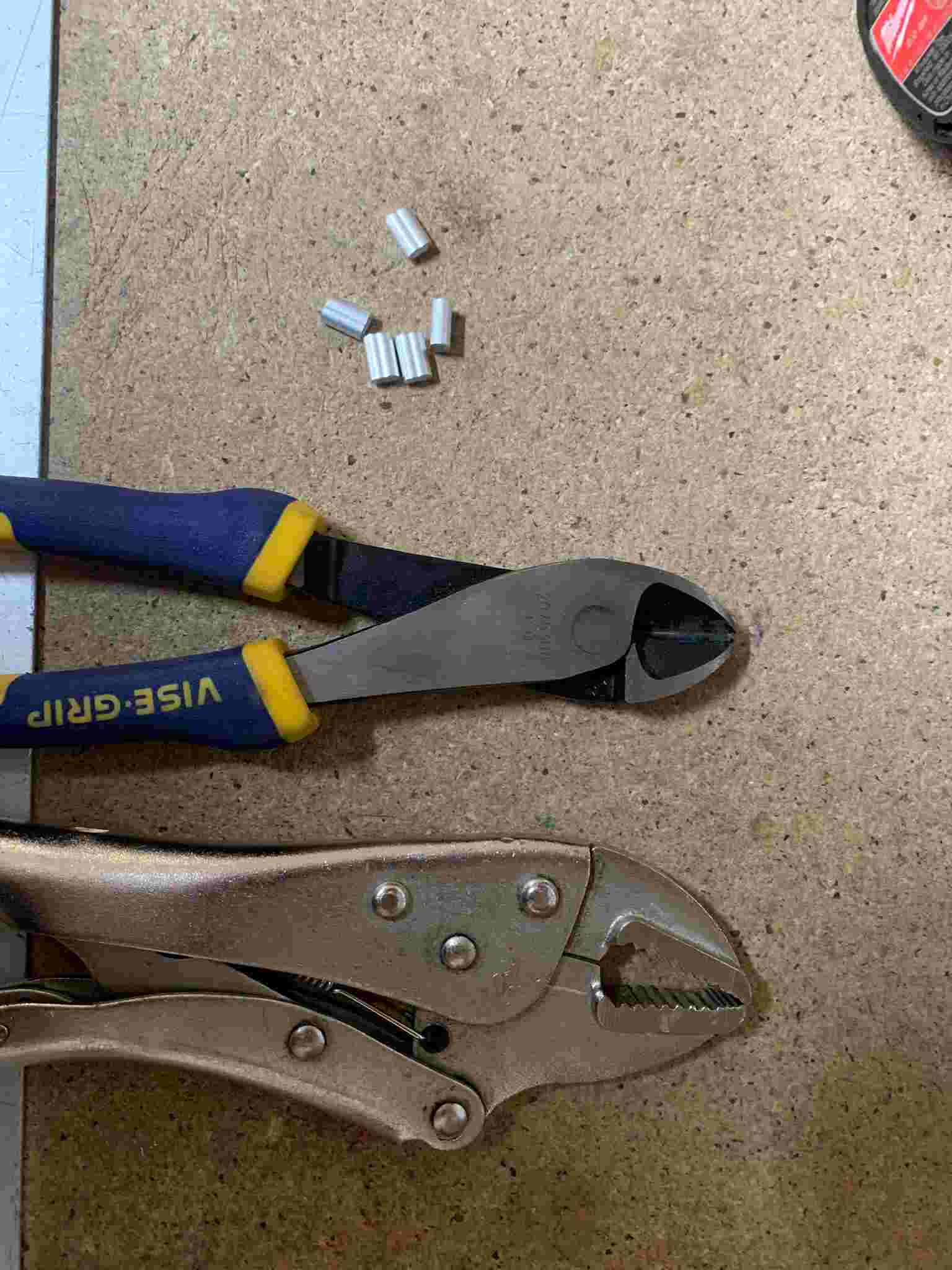
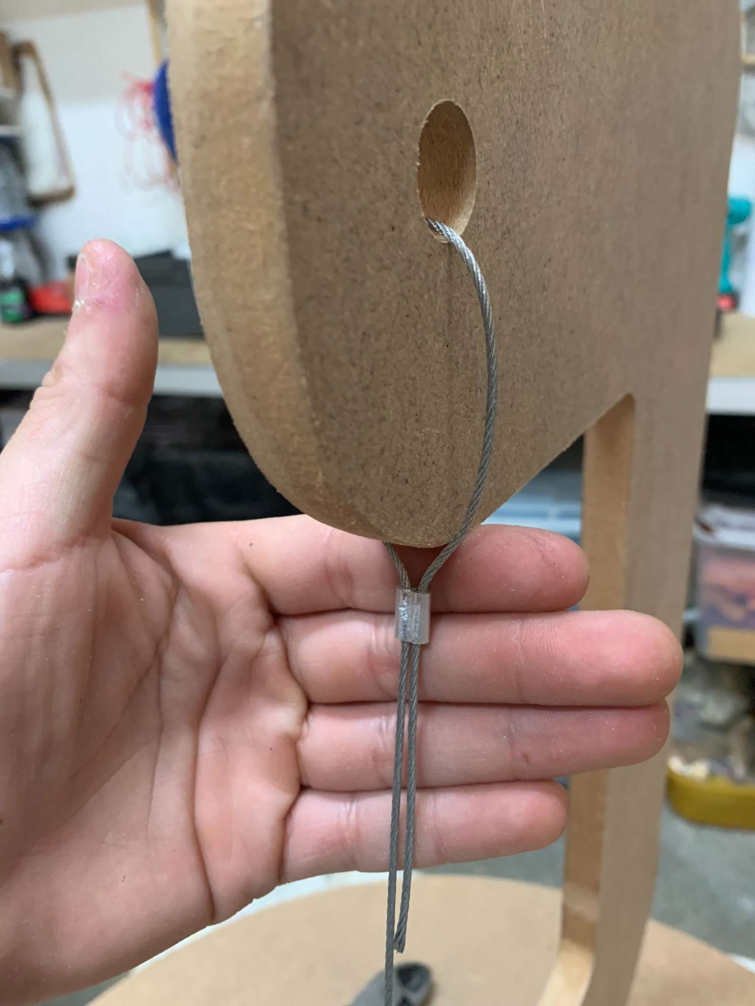
I then used 4mm steel wire to tighten everything together, using a pair of cutting pliers, clamp pliers and some aluminum wire clamps I was able to assemble the wire that holds the table's weight (purple wire in the previous diagram).
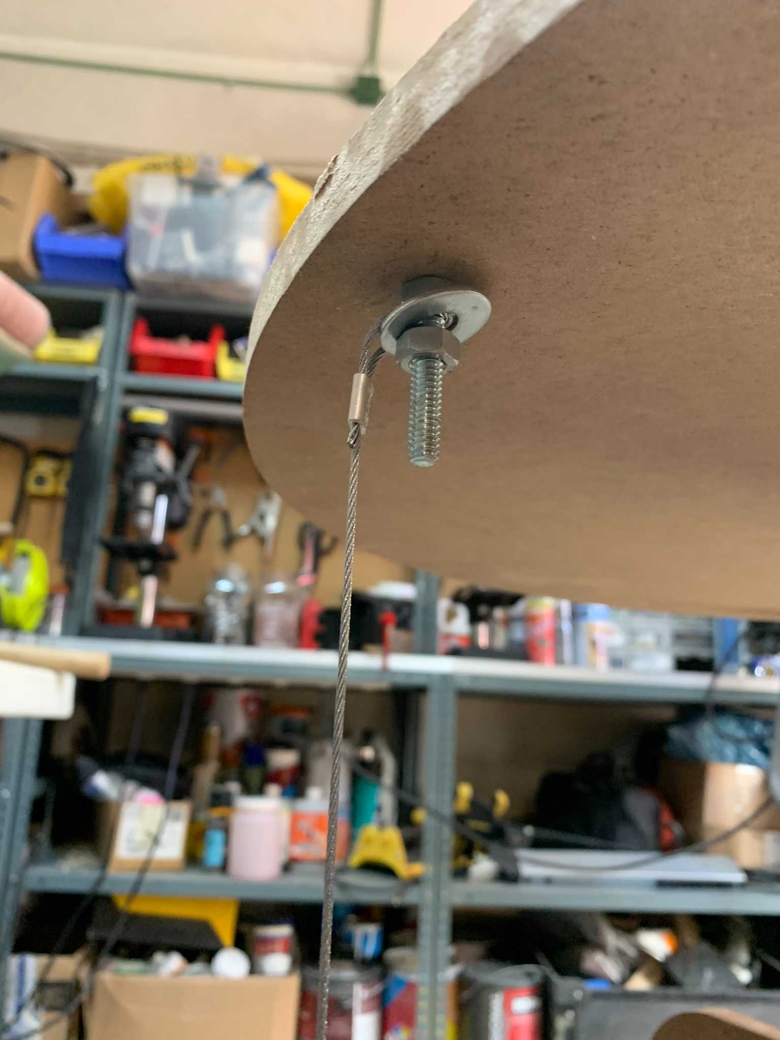
For the auxiliary wires (orange wires on the diagram) I devised a way to tension the wires after they're installed in order to easily level the table and assure all wires are in tension. A nut holds a metal washer that sequentially holds the wire along a screw, if the nut is tightened, the wire is tensioned.
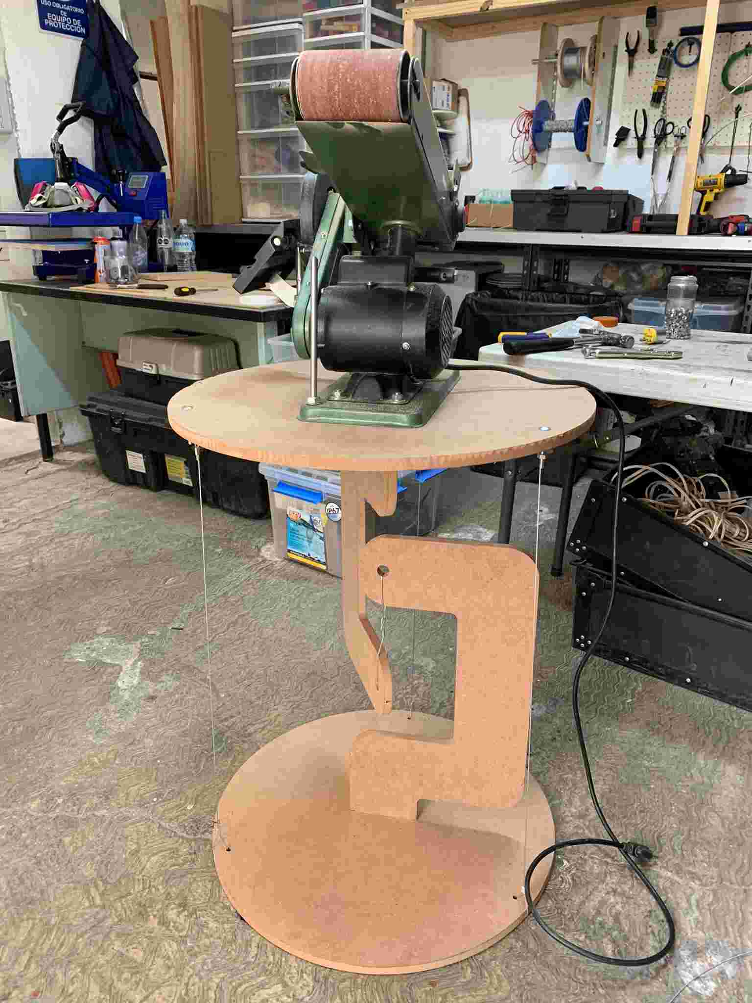
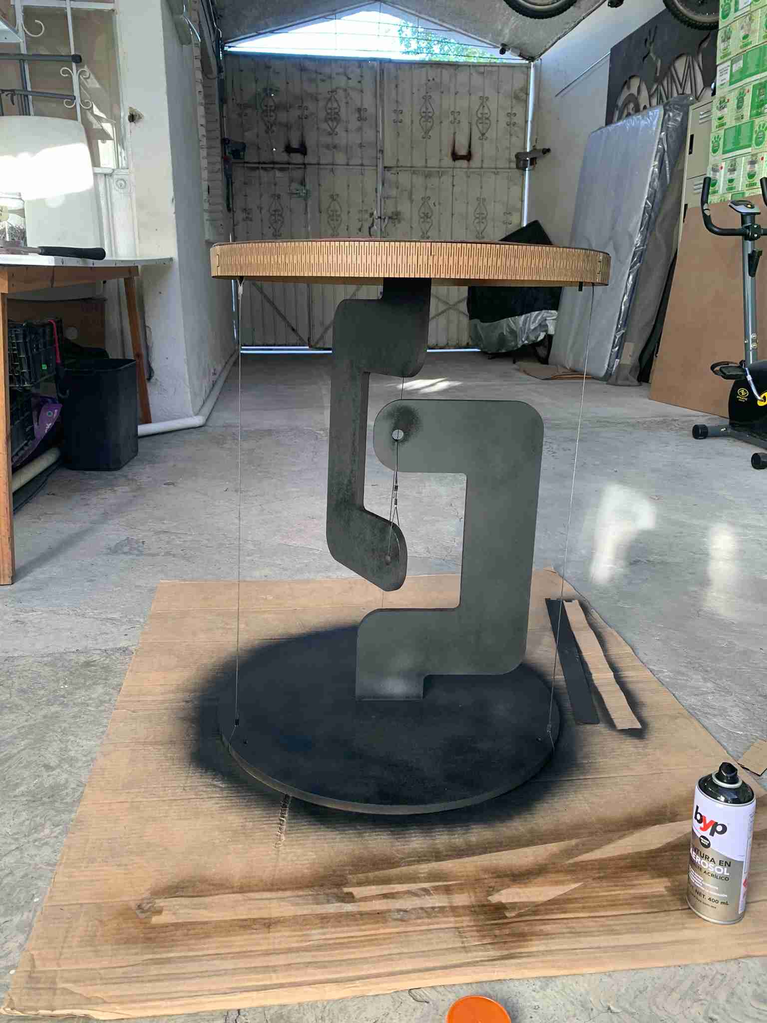
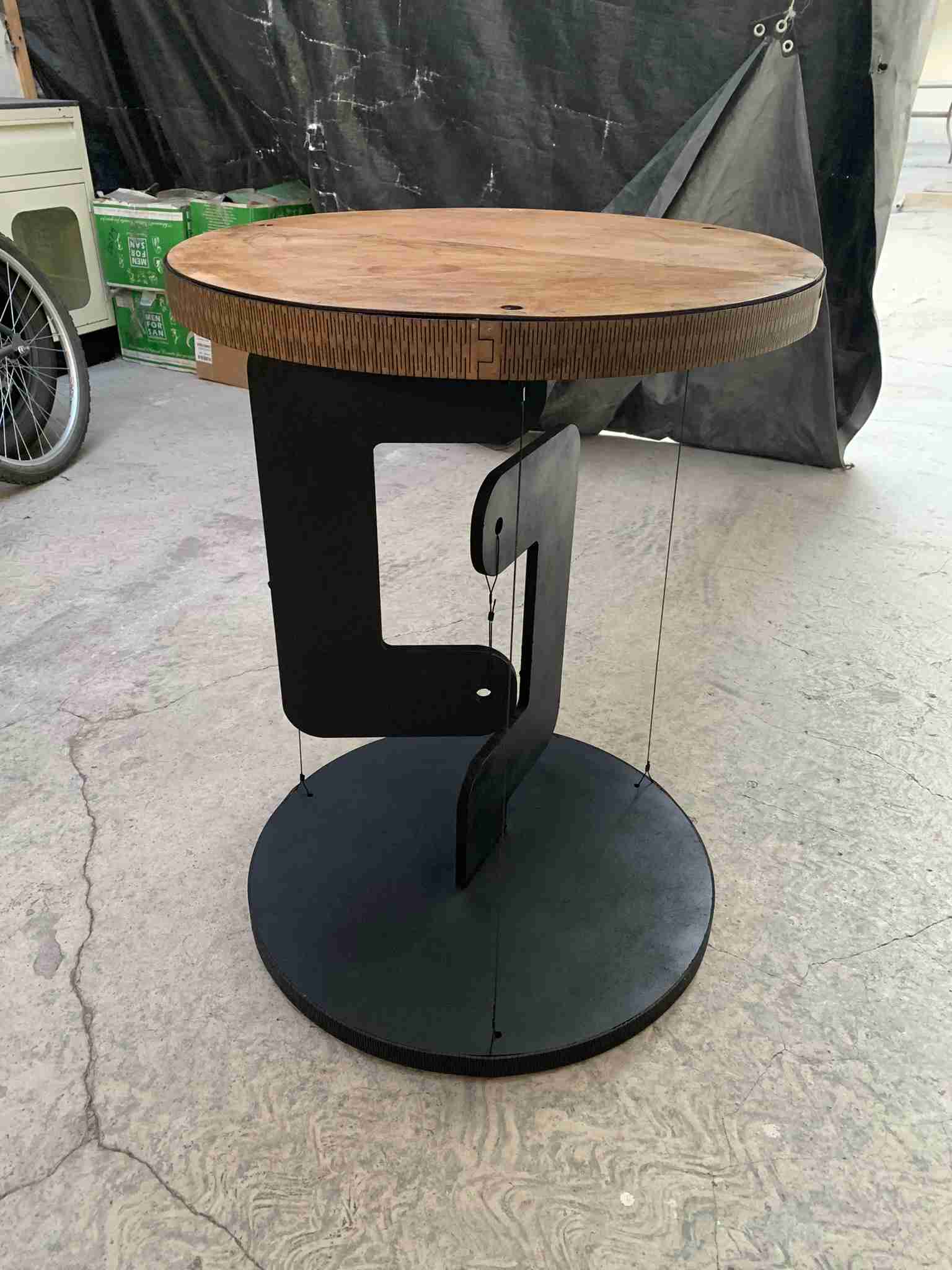
The table's design has three wires separated 120 degrees from each other, allowing to maintain the table upright and leveled. This assembly resulted in the following images: On the right the finished assembly, and on the right, the table holding the weight of the belt sander! (Weight around 6 kilograms).
Now, the table is functional, but certainly not very pretty, so with the help of some spray paint and some laser cutting this is about to change!
Making it pretty:
<I like very much the slotted pattern produced by laser-cutted living hinges, and also solves the problem of trying to bend wood along a circle! So, using OnShape I designed a living hinge whose length was the table's circumference divided by three, so by cutting three of those pieces, I could cover the entire circumference. The decorative strips were made out of 3mm MDF, and then covered with transparent acrylic spray to give them some shine and a darker appearance.
Also, I cutted two semicircles out of 3mm plywood that together covered the exact size of the table. Making semicircles was necessary because the whole 60cm of the table's diameter exceeded the maximum dimensions of the laser cutter I was using.
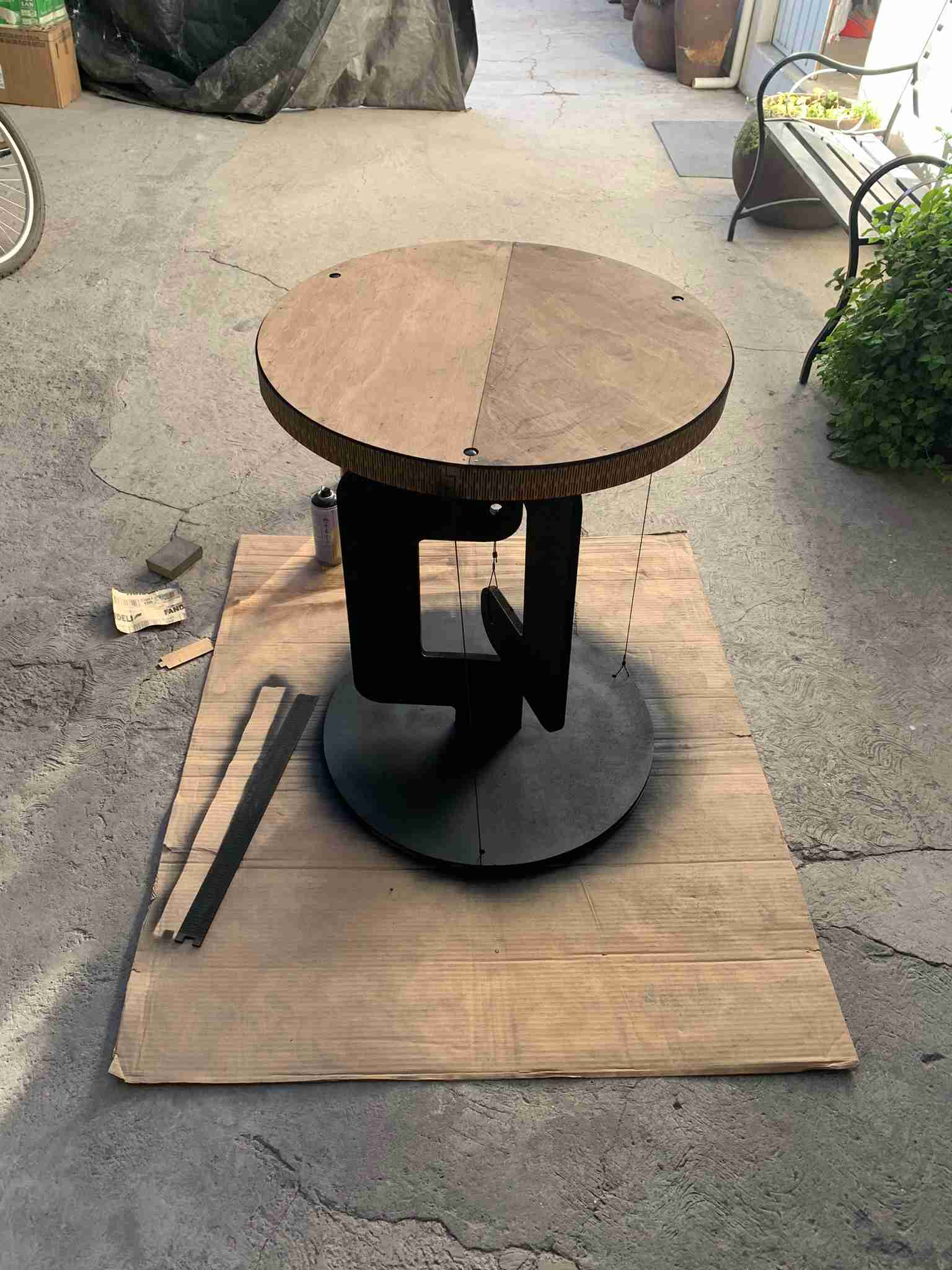
To protect the plywood from moisture and to add a glimpse of color to it I used a Danish Oil finish applied with a piece of cloth. Then, using some matte black spray paint, I painted all of the MDF structure black, giving it a nice minimalistic finish.
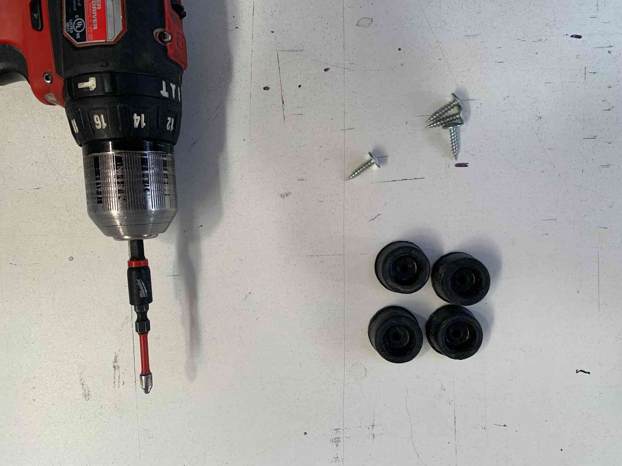
Once the paint dried, I fastened all of the aesthetic pieces using some nails and wood glue. And last but not least, I added some rubber feet using screws, so the table doesn't slip on the floor or get damaged by it.

In the end, I was really satisfied with the results:
Thank you for taking a look into my 7th week's progress!