Ralph Breaks The Network!
COMMUNICATIONS:
In the communications module of my project, the objective was to design, construct, and connect various wired or wireless nodes with specific network or bus addresses. This setup was intended to forge a network capable of facilitating communication between different electronic boards, each serving as a node within the broader system.
Understanding Communication Protocols
The core of this task involved selecting and implementing the appropriate communication protocols between processors. Protocols like UART, SPI, and I2C are fundamental in defining how these communications occur, each suited to different types of data transfer requirements:
- UART (Universal Asynchronous Receiver/Transmitter)
- SPI (Serial Peripheral Interface)
- I2C (Inter-Integrated Circuit)
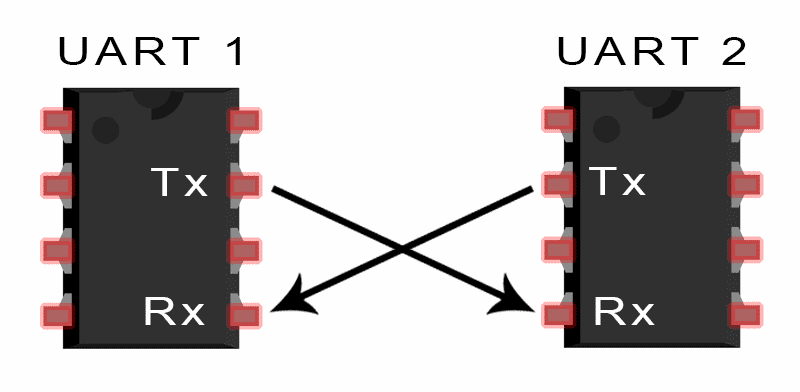
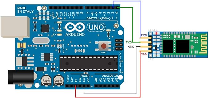
UART protocol is instrumental for serial communication, acting as a bridge between parallel and serial interfaces. At one end of a UART setup, you typically have a bus that includes around eight data lines along with some control pins. At the other end, you find the two serial wires, RX (Receive) and TX (Transmit). The key feature of UART is its simplicity and effectiveness in systems where communication complexity is minimal but reliability is paramount. It does not require a clock signal to synchronize transmissions, which simplifies the design and reduces the need for additional wiring.
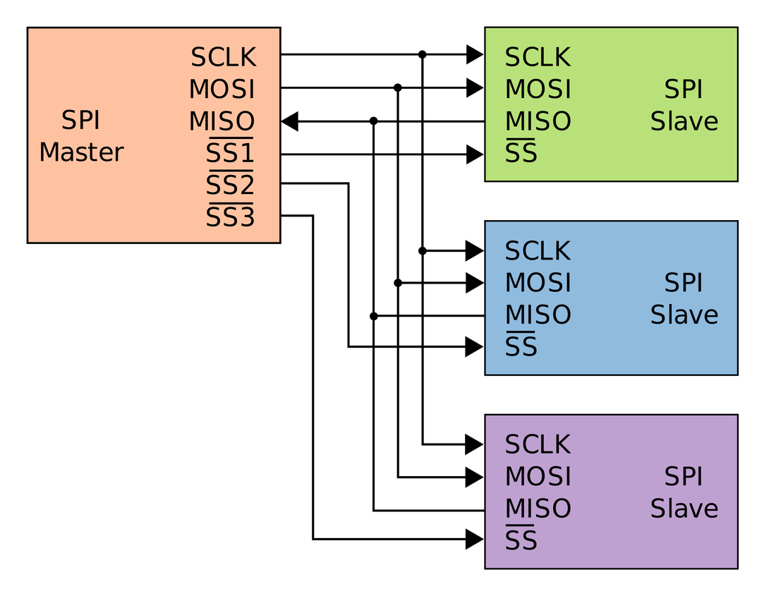
SPI is another significant communication protocol, known for its higher speed compared to UART. It operates based on a master-slave architecture, where the master device controls the clock and, thus, the data flow in the system. This protocol uses four wires - one for the clock (SCK), one for master output/slave input (MOSI), one for master input/slave output (MISO), and one select wire (SS) to manage multiple slaves. SPI is highly effective in environments where devices need to communicate quickly and are physically close to each other.
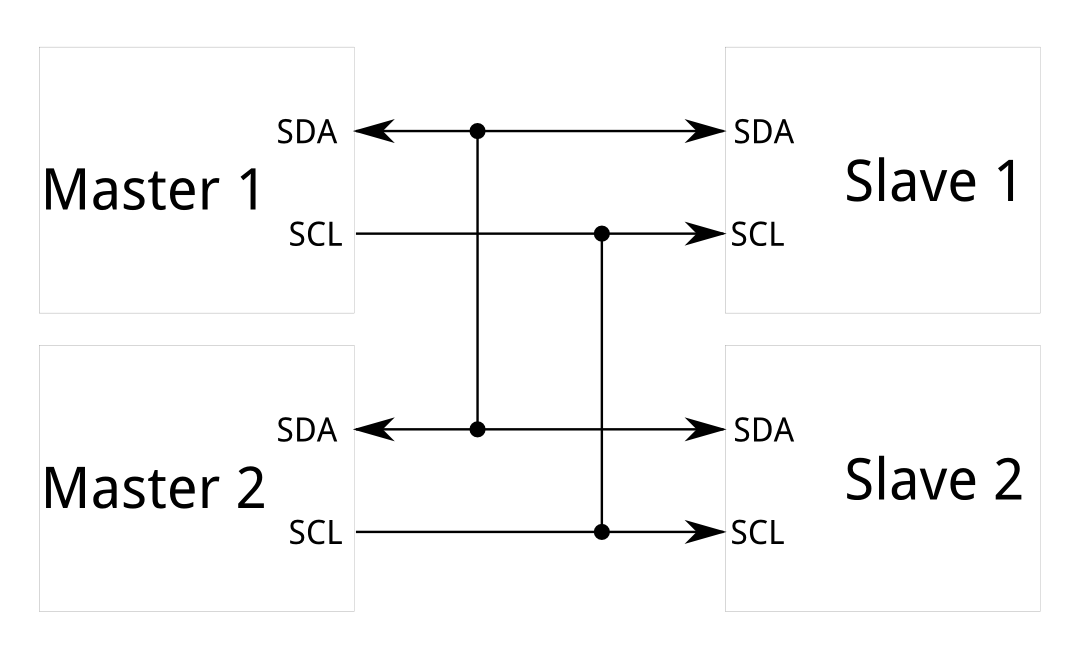
I2C is used for complex communications within integrated circuits. This protocol utilizes just two wires - one for the clock (SCL) and one for data (SDA), making it ideal for applications where wiring needs to be minimized. I2C supports multiple master and slave devices, with each device addressed using a unique identifier. This flexibility makes it particularly useful for connecting multiple sensors and other peripherals to a single processor with minimal pin use.
Below, I present a comparative table outlining the key characteristics and distinctions between the UART, SPI, and I2C communication protocols. This comparison aims to provide a clear overview of their respective attributes, allowing for informed decisions when designing or choosing a protocol for specific applications.
| Characteristic | UART | SPI | I2C |
|---|---|---|---|
| Designation of Pins | TxD (Data transmission), RxD (Data reception) | SCLK (Serial Clock), MOSI (Master output, slave input), MISO (Master input, slave output), SS (Slave selector) | SDA (Data), SCL (Serial Clock) |
| Data Speed | Typically between 230 Kbps to 460 Kbps | Normally supports between 10 Mbps to 20 Mbps | Up to 3.4 Mbps, with some variants reaching up to 1 Mbps |
| Distance | Less than 15 meters | Primarily designed for short-distance, on-board communications | Similar to SPI, suitable for on-board communications |
| Hardware Complexity | Relatively low | Moderate | High, especially when dealing with multiple masters |
| Number of Masters | Not applicable (peer-to-peer) | One master | Multiple masters |
| Clock | No external clock; each device uses its own internal clock | Shared clock signal between master and slaves | Common clock signal shared among all masters and slaves |
| Protocol | 8 bits with one start bit and one stop bit | Protocol varies by implementation; typically company-specific | Uses a start and stop bit, with an acknowledgment bit (ACK) every 8 bits |
| Software Addressing | Not necessary as communication is only between two devices | Slave select (SS) lines are used to manage multiple slaves | Addresses are assigned to each slave; up to 127 devices can be addressed |
| Advantage | Simple, ideal for quick two-device connections; commonly used with RS232 or RS485. | Full duplex communication; high data rate; lower energy consumption than I2C; uses push-pull drivers. | Only two wires needed for multiple device communication; supports multiple masters; features flow control with the open-collector setup. |
| Disadvantage | Limited to one-to-one communications; requires matching baud rates to avoid errors. | Requires additional connections for more slaves; no inherent flow control. | Higher complexity and potential for bus contention; half-duplex; may overload the processor in complex configurations. |
This table elucidates the functionalities and limitations inherent in each protocol, making it easier to understand which might be best suited for different types of networked communications within electronic systems.
You can see more info in this week's Group Assignment.
The Network.
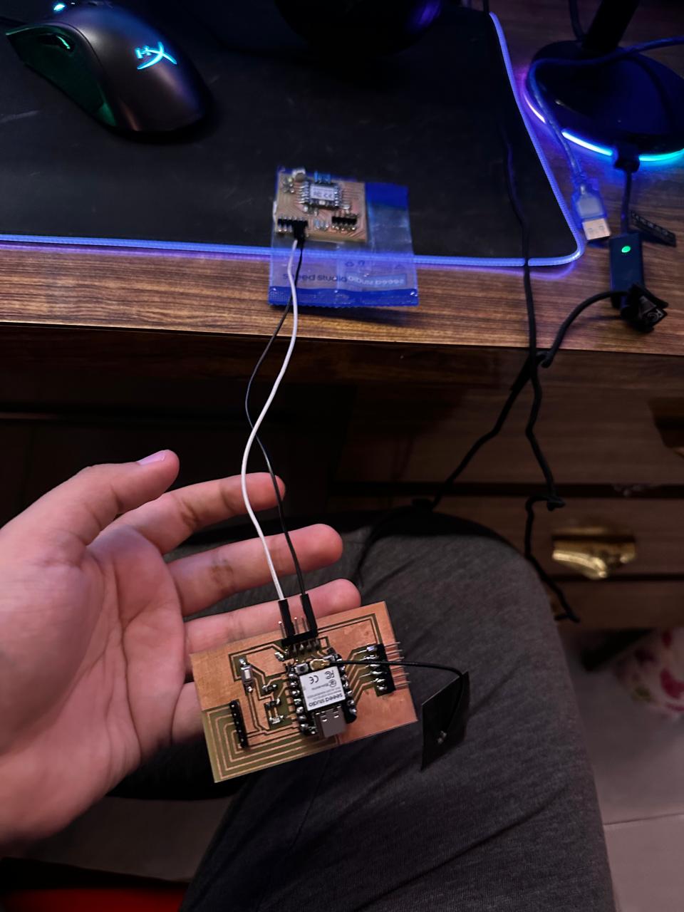
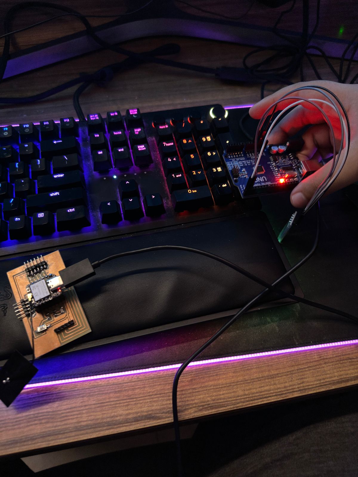
For my individual assignment, I chose to explore two distinct communication protocols to facilitate interaction between various devices in my network. Specifically, the goal was to create a setup where a button press on the XIAO ESP32-C3 would simultaneously turn on an LED on the XIAO RP2040 via UART and on an Arduino module via Bluetooth.
Here’s a breakdown of how I implemented each protocol:
System Design:
The system consists of three main components:
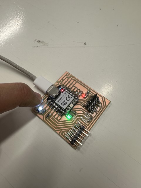
- XIAO ESP32-C3: Acts as the central controller that initiates commands.
- XIAO RP2040: Receives commands via UART from the ESP32-C3.
- Arduino Module: Receives commands wirelessly via Bluetooth.
Communication Protocols:
- Wired Communication (UART): The connection between the ESP32-C3 and the RP2040 utilized UART protocol, known for its reliability and simplicity in handling direct microcontroller-to-microcontroller data transfer.
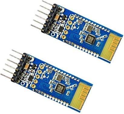
- Wireless Communication (Bluetooth): The Arduino module was equipped with an HC-05 Bluetooth module, allowing it to receive commands from the ESP32-C3's onboard Bluetooth.
UART Communication between XIAO ESP32C3 and XIAO RP2040
As mentioned before, I utilized UART for serial communication between two microcontrollers: the Xiao ESP32-C3 and the RP2040. UART, being asynchronous, does not require a shared clock between the devices, which simplifies the setup.
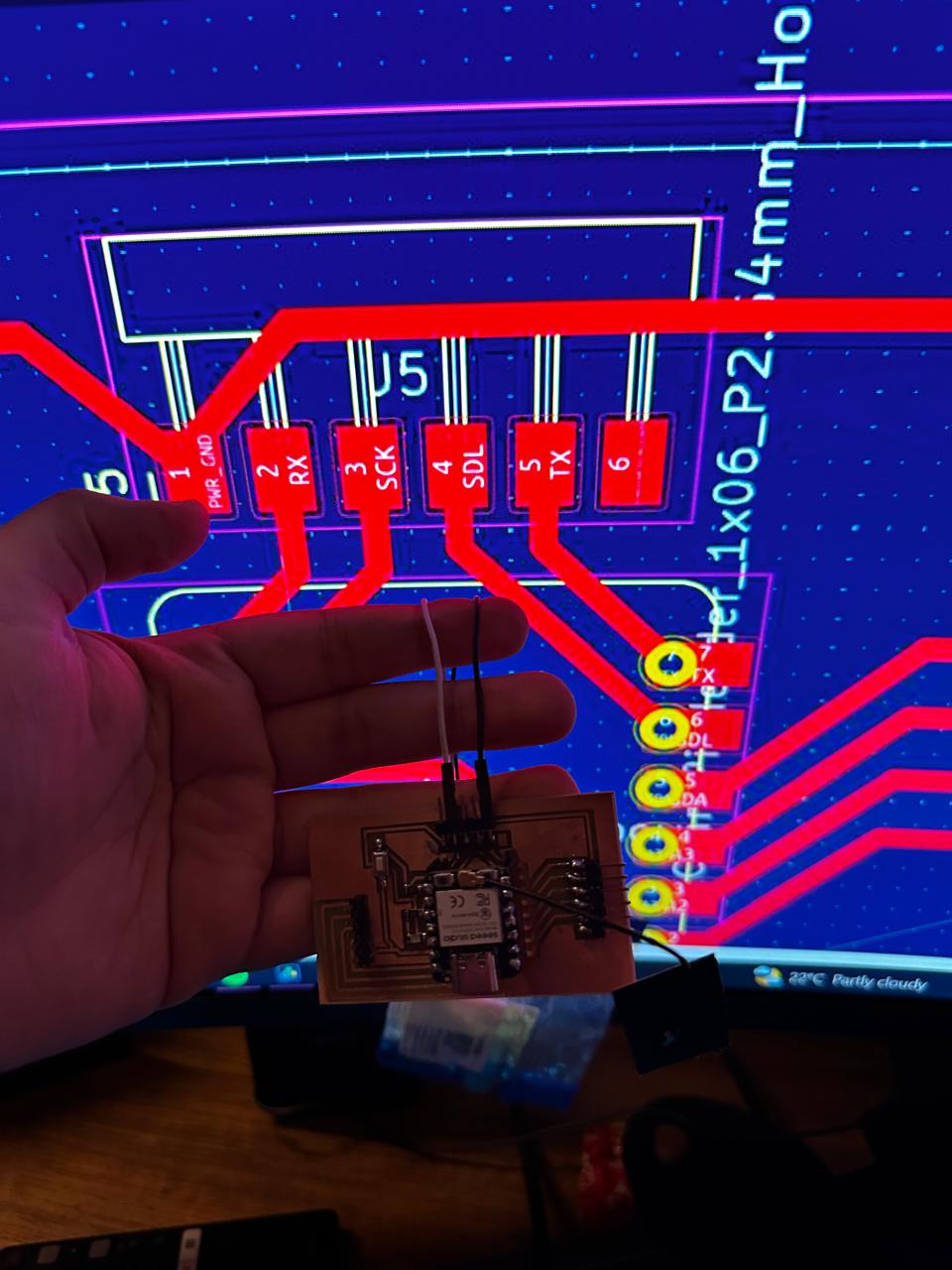
I connected the TX pin of the Xiao ESP32-C3 to the RX pin of the RP2040 and vice versa to enable full-duplex communication, where both devices can send and receive data simultaneously.
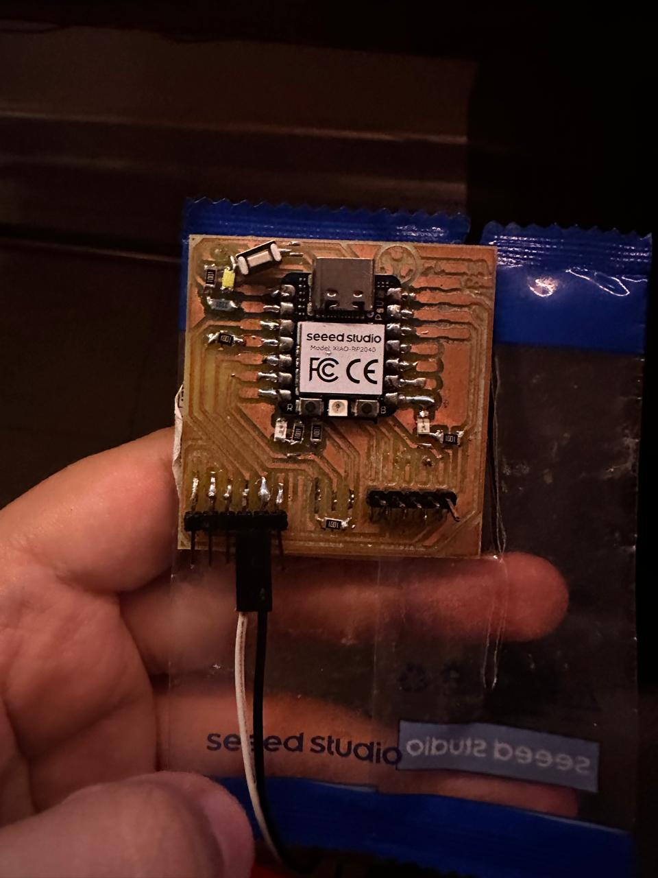
XIAO RP2040 TX and RX pins:
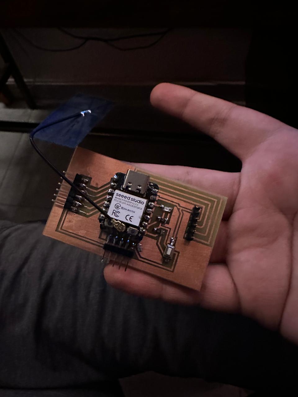
XIAO ESP32C3 RX and TX pins:
This setup was particularly useful for sending control commands and receiving responses between the microcontrollers, allowing them to operate cohesively in real-time.
The Code:
XIAO ESP32C3 Code:
Code Explanation:
- Pin Initialization:
- buttonPin (pin 20) is set up as an input with an internal pull-up resistor. This configuration ensures the pin reads HIGH when the button is not pressed, and LOW when pressed, simplifying the wiring by not needing an external pull-up resistor.
- ledPin (pin 8) is set up as an output to control an LED.
- Serial Communication Setup:
- Serial.begin(9600); initializes the serial connection to the Serial Monitor at 9600 baud rate for debugging purposes. This allows messages to be printed out to the IDE’s Serial Monitor.
- Serial1.begin(9600, SERIAL_8N1, 20, 21); sets up another UART channel (Serial1) at 9600 baud rate with the typical configuration (8 data bits, no parity, 1 stop bit) using GPIO pins 20 and 21 for RX and TX respectively. This is used for UART communication with another microcontroller.
- Main Loop:
- The loop continuously checks if the button connected to buttonPin is pressed. If it is (digitalRead(buttonPin) == LOW), it sends the character '1' over Serial1 (UART) to the RP2040, indicating that the button has been pressed.
- It also checks if there is incoming data on Serial1. If data is available (Serial1.available()), it reads the incoming character (Serial1.read()), prints a debug message to the Serial Monitor, and controls the LED on ledPin. If the command received is '1', the LED turns on for 500 milliseconds and then turns off.
Serial in Arduino and compatible environments (like the one used for Xiao ESP32-C3) refers to serial communication, which involves sending data one bit at a time, sequentially, over a communication channel or computer bus. Serial communication is used widely in microcontroller-to-microcontroller communication as well as for communicating with computers and other devices.
Serial vs. Serial1:In many Arduino-compatible boards, Serial typically refers to the USB communication between the microcontroller and the computer (for debugging, uploading, etc.), while Serial1, Serial2, etc., refer to additional UART peripherals that can be used for communication with other devices or microcontrollers.
XIAO RP2040 Code:
Code Explanation:
- Include and Pin Assignments:
- #include Arduino.h: Includes the Arduino core library, enabling the use of standard Arduino functions and constants.
- buttonPin and ledPin: GPIO pins are defined for the button and LED, respectively. Here, GPIO 26 is used for the button, and GPIO 22 is used for the LED.
- Setup Function:
- pinMode(buttonPin, INPUT_PULLUP): Configures the button pin as an input with an internal pull-up resistor. This means the pin will read HIGH when the button is not pressed, and LOW when it is pressed.
- pinMode(ledPin, OUTPUT): Sets the LED pin as an output.
- digitalWrite(ledPin, LOW): Initializes the LED state to OFF.
- Serial.begin(9600): Initializes serial communication at 9600 baud rate to the Serial Monitor for debugging outputs.
- Serial1.begin(9600): Starts UART communication at 9600 baud rate. This is the setup for communicating with another device via UART.
- Loop Function:
- The loop() function contains the core logic for button interaction and communication:
- if (digitalRead(buttonPin) == LOW): Checks if the button is pressed. If yes, it executes the following commands:
- Serial.println("Button pressed - Sending '1'"): Sends a debug message to the Serial Monitor indicating that the button was pressed and a command is about to be sent.
- Serial1.write('1'): Sends the character '1' over UART to another connected device (in this case, potentially the Xiao ESP32-C3).
- delay(200): Implements a 200-millisecond debounce delay to prevent multiple detections of a single button press.
- Receiving Commands via UART:
- if (Serial1.available()): Checks if any data is available to read from the UART buffer.
- char cmd = Serial1.read(): Reads the incoming character from UART.
- Serial.print("Received command: "); Serial.println(cmd): Prints the received command to the Serial Monitor.
- if (cmd == '1'): If the received character is '1', it executes the following:
- digitalWrite(ledPin, HIGH): Turns the LED ON.
- delay(500): Keeps the LED ON for 500 milliseconds.
- digitalWrite(ledPin, LOW): Turns the LED OFF.
- delay(100): A short delay at the end of the loop to prevent flooding the Serial Monitor and UART communication with excessive data.
Problems:
One of main problems was that I was having initial difficulty in setting up stable UART communication between the two devices where they didn't appear to communicate at all.
However, I was able to fix this by configurating the UART ports correctly on both microcontrollers and ensured the correct pin mapping and baud rate (9600 Bps) settings.
Video:
BLE communication with XIAO ESP32C3 and Arduino:
This part of this week aimed to establish a communication link between a Xiao ESP32-C3 and an Arduino using a Bluetooth module. The objective was to explore the capabilities of Bluetooth Low Energy (BLE) for discovering and potentially connecting to nearby Bluetooth devices, specifically targeting the HC-05 Bluetooth module connected to an Arduino.
The HC-05 Module:
Hardware Setup:
Connected to an HC-05 Bluetooth module configured in the role of the advertised device.
Software Implementation
The ESP32-C3 was programmed using the following main libraries and setup:
- Libraries used:
- BLEDevice.h
- BLEUtils.h
- BLEScan.h
- BLEAdvertisedDevice.h
- Code Description:
- The ESP32-C3 was set up to perform active BLE scanning for a set period (5 seconds).
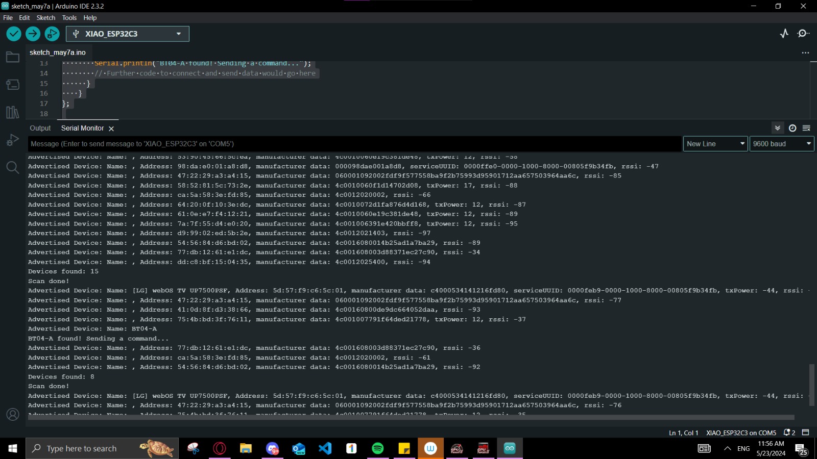
- A custom callback class, MyAdvertisedDeviceCallbacks, was implemented to handle discovered devices. When the HC-05 module (identified by its advertised name "BT04-A") was detected, the ESP32-C3 logged a success message indicating recognition.
- Although the device was successfully recognized and could "greet" the HC-05 by identifying its name, no further command transmission or interactive communication was established beyond this discovery phase.
Serial Monitor:
Video Result:
- Communication Limitation: While the ESP32-C3 could detect the HC-05 module, the system was not configured to establish a two-way communication link that would allow sending and receiving of specific commands or data.
- Implementation Constraints: The BLE scanning implementation was limited to device discovery and identification. No pairing or connection establishment coding worked correctly due to certain hardware limitations, which is required for further communication.
Conclusion:
The project successfully demonstrated the BLE scanning capabilities of the Xiao ESP32-C3, identifying a specific HC-05 Bluetooth module connected to an Arduino. However, future work is required to enable full duplex communication, expanding the project's scope to include interactive command exchange and potentially more complex data handling scenarios. This documentation provides a basis for further development and troubleshooting in projects involving BLE communications with ESP32-based systems.
The Files:
Below you can find the download links for all of the files from this week.