7. Computer-Controlled Machining
On this week we had to create something big using the CNC machine, which is also a process where the material is removed to have a final object. The most common materials are wood, plastic, MDF, PVC, among others. The router is perfect for creating big assembleable object, such as benches, chairs, furniture, and so on.
General Notes
This week we also had a group page to know about computer controlled machining. For this the local instructor gave us some steps to follow:
- Design of the object.
- Export design with the specified format depending on wether it is 2D (.dxf/.dwg) or 3D (.stl).
- Postprocessing using a software to create the toolpath. In FabLab Puebla we used VCarve.
- Export the G-Code from the postprocessor.
- Use the G-Code in the CNC router to control it.
There are also some security measures to follow when using the router:
- Clean floor.
- Safety distance between you and the machine.
- Be aware of the emergency stop.
- Check machine for wastes in the rails.
- Make sure that the material is completely secured.
- No loose clothing.
- Use breathing mask.
- Use impact-proof safety goggles.
- Use noise protection headset.
- Use safety boots/shoes.
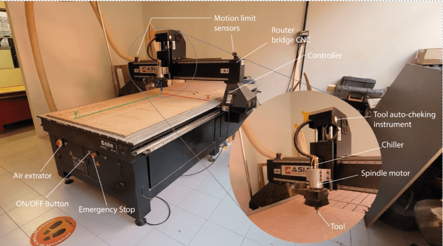
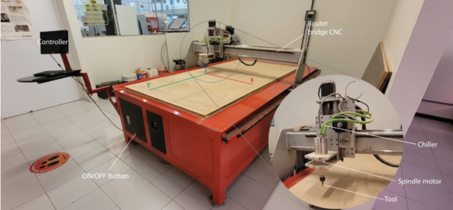
In FabLab Puebla there are two big CNC routers: Asia Robotica shop-1325 (first picture) and a generic one made by the university (the second picture).
Characterization
For the characterization there were some tests documented in the group page in order to the design rules and the tool we would be using. The design rules and the tool that I used according to what was documented in the group page are the following:
- Tool: 1/4" Upcut Carbide End Mill.
- Hole modification: dog-bone.
- Machining operations: profile.
- Fixture to machine bed: nails.
Design of the Object
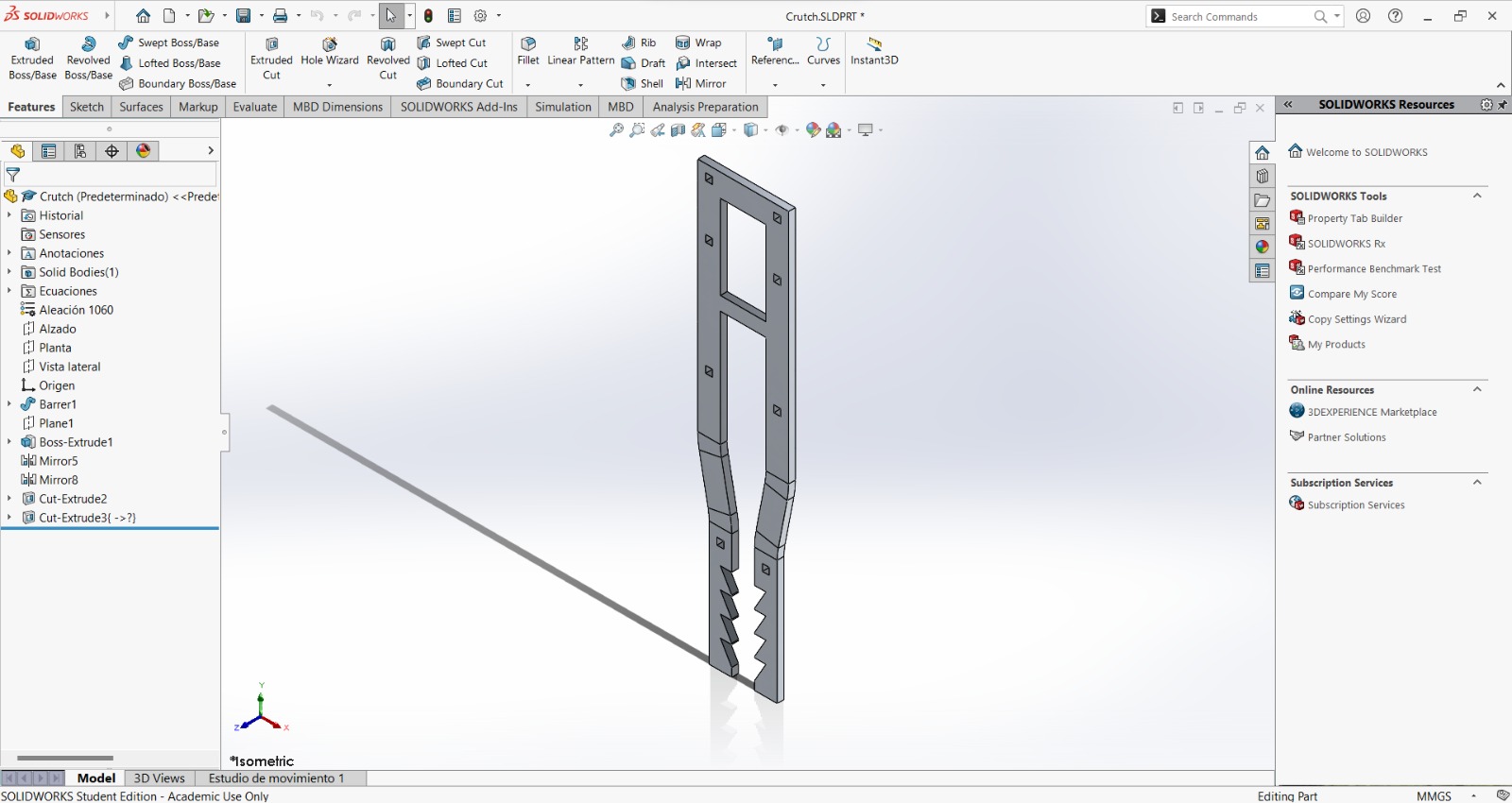
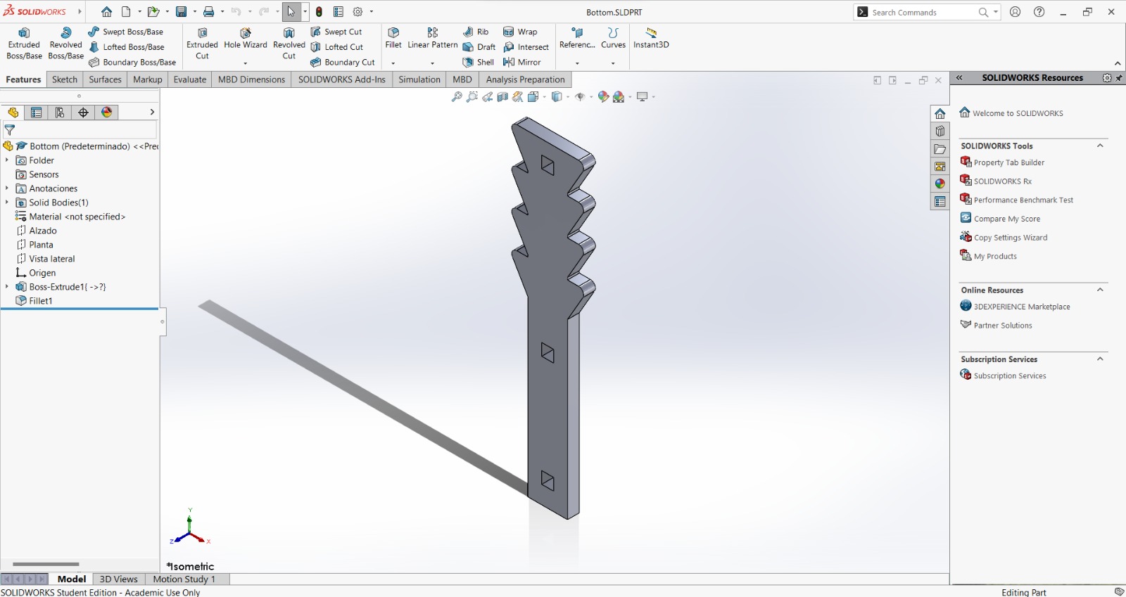
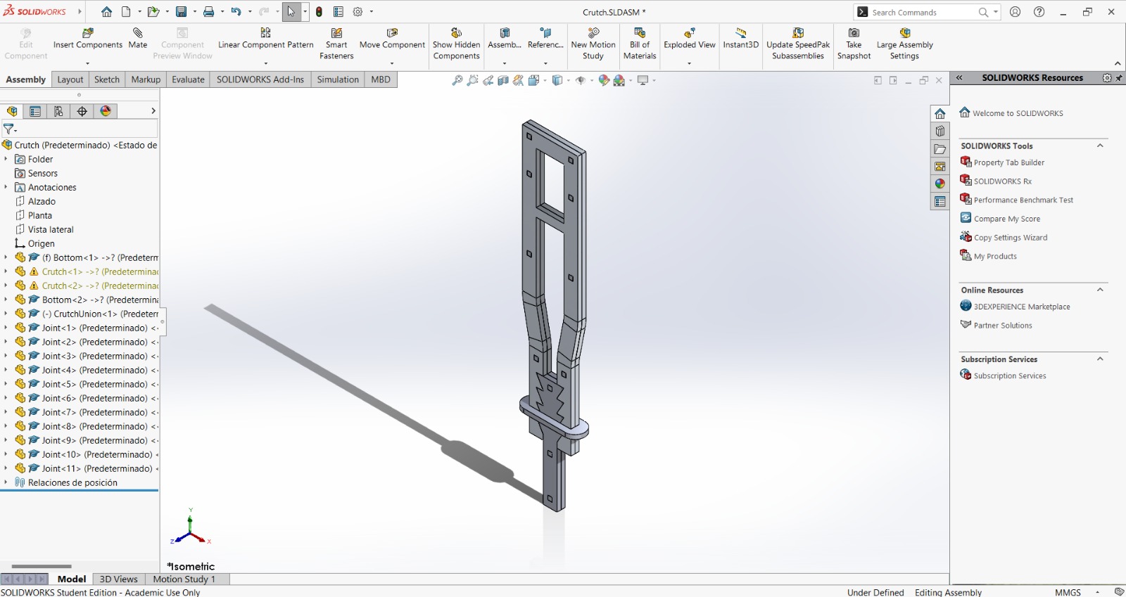
For the design I made a crutch, because there's a friend who was using one. However, the crutch he was using didn't fit him, so I wondered if I could make one that could fit him. Also, the crutch was made by cutting two frames and two bottom pieces to join them face to face with little joints. The height may also be adjusted with the saw-type bottom, while keeping it in its place with the crutch union. The crutch design consists of 4 pieces (between parenthesis are the amount of units I cut form each):
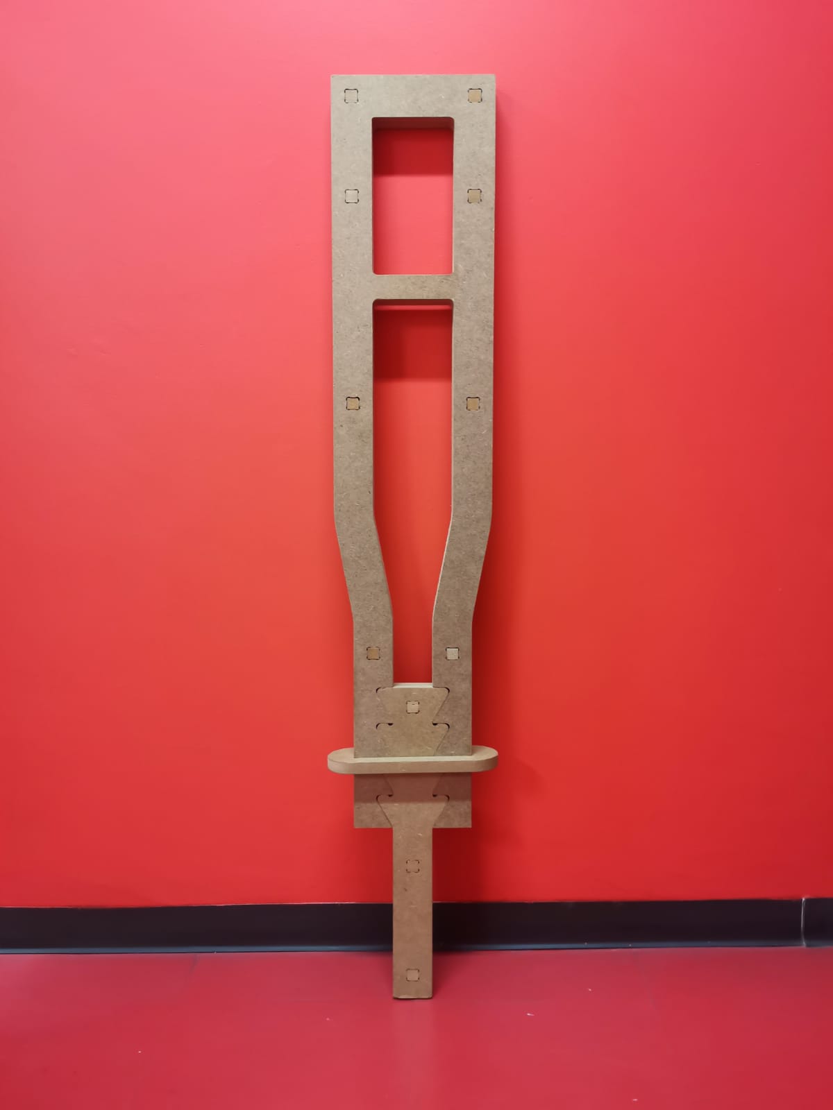
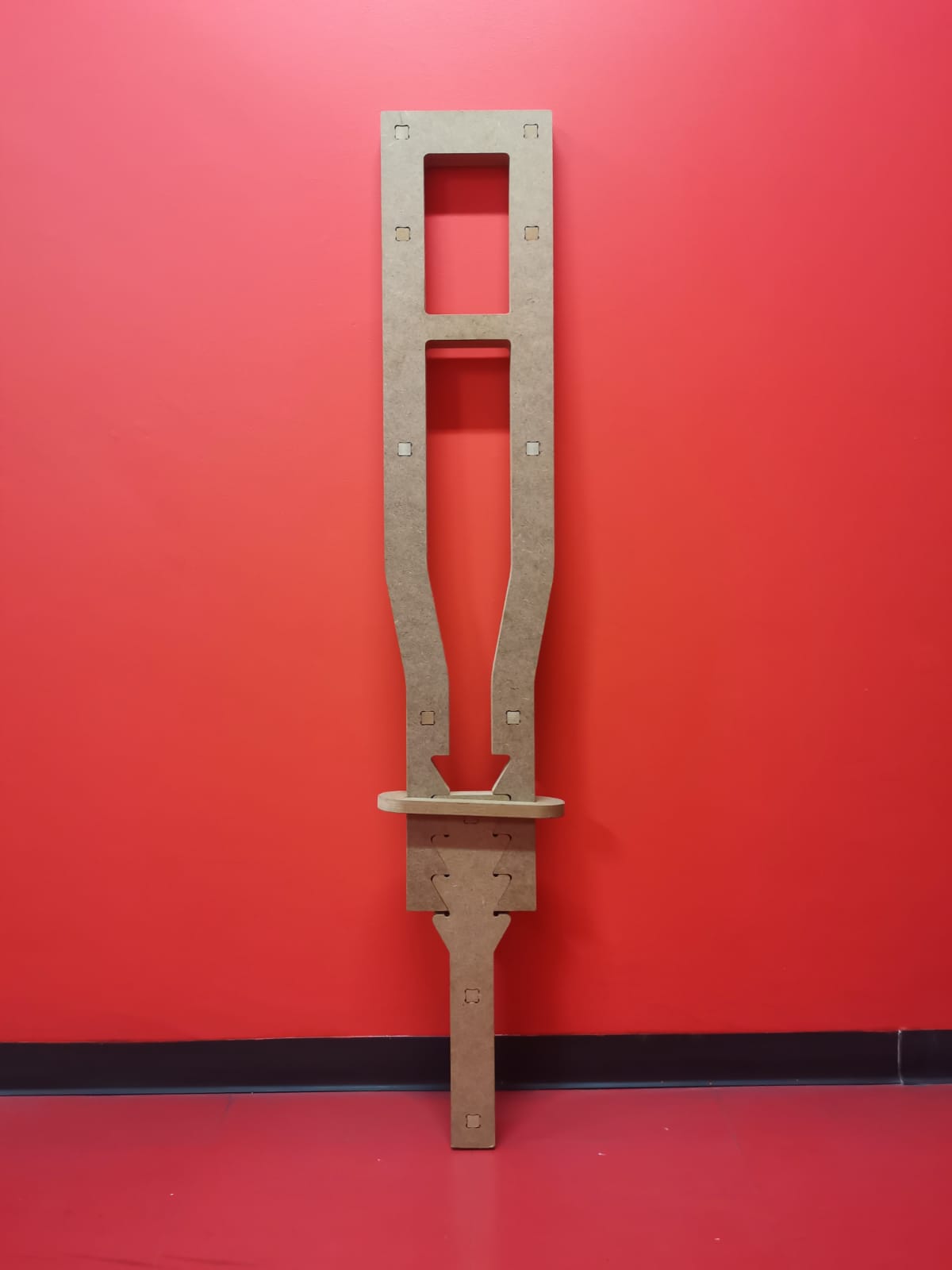
Crutch frame (2):
Crutch bottom (2):
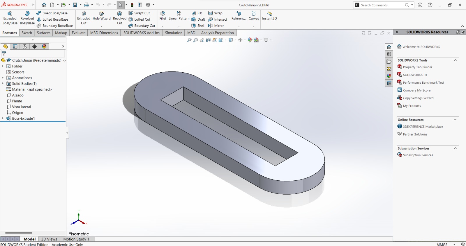
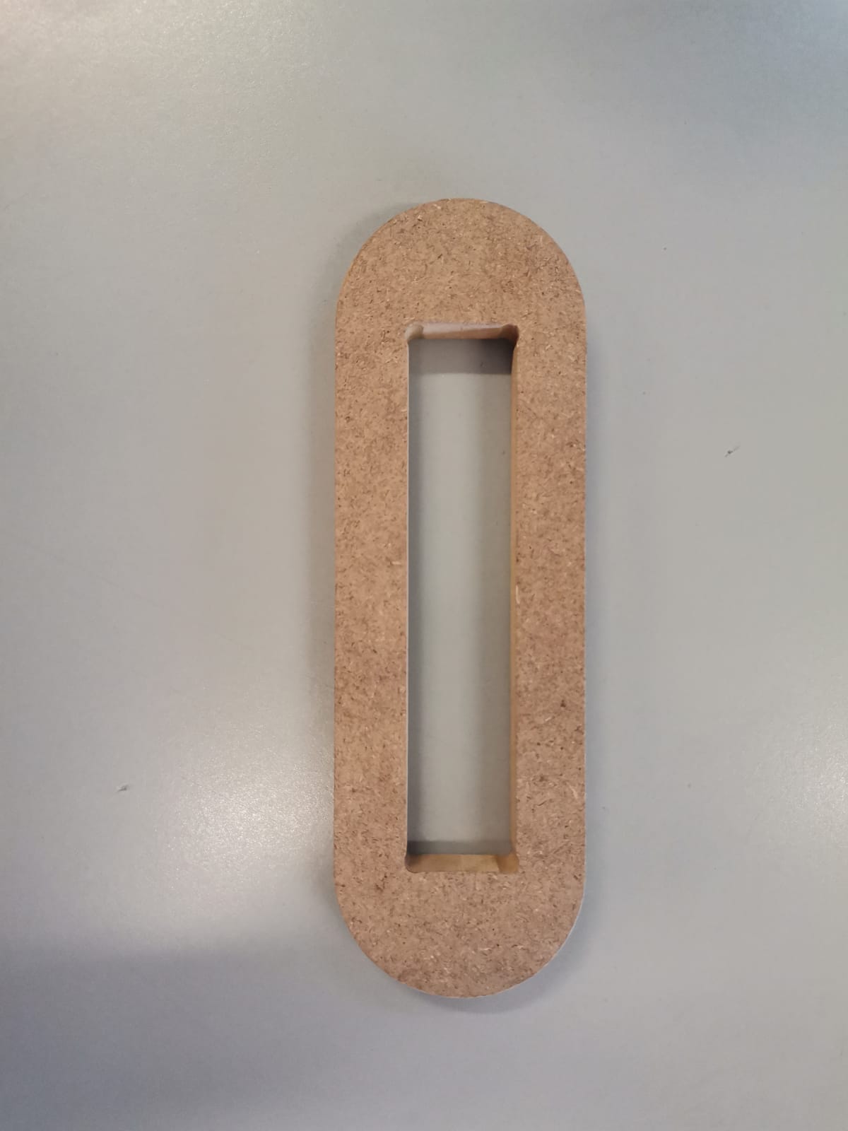
Crutch union (1):
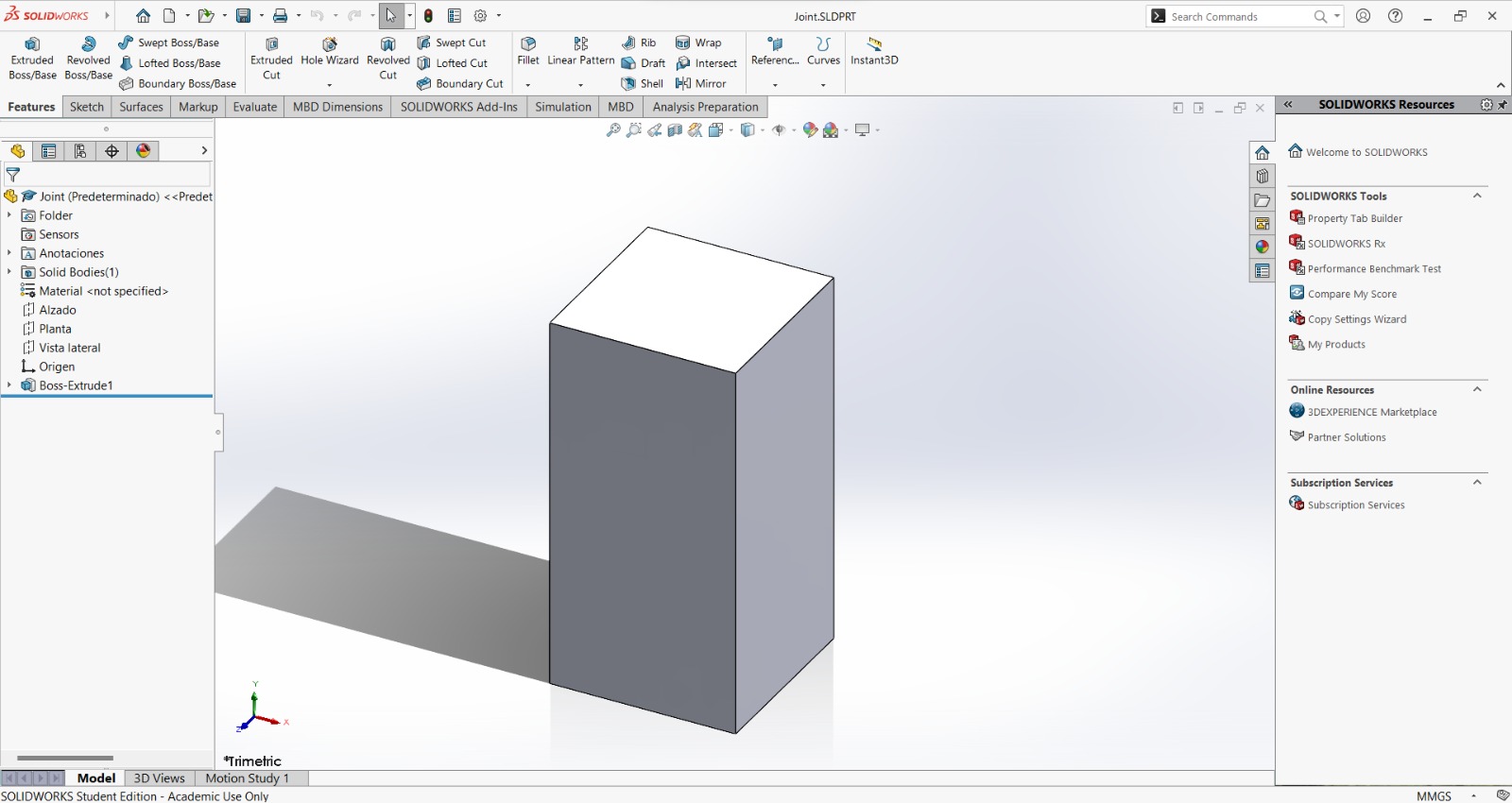
Joint (11):
And the final assembly goes as the following:
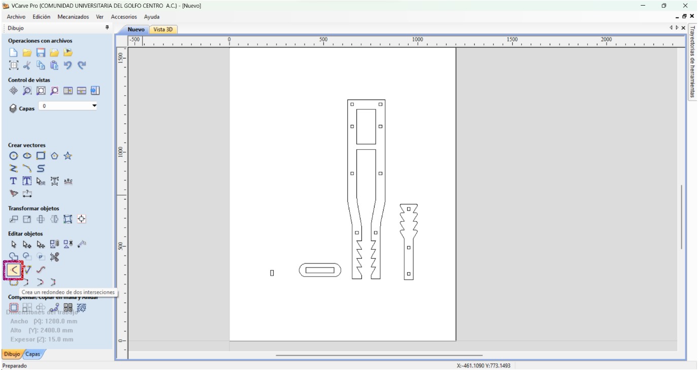
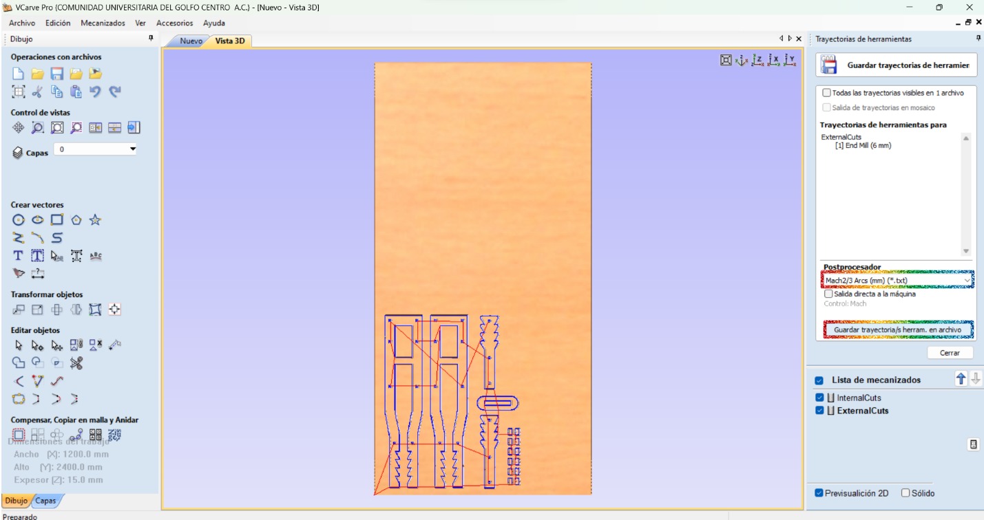
Toolpath Creation
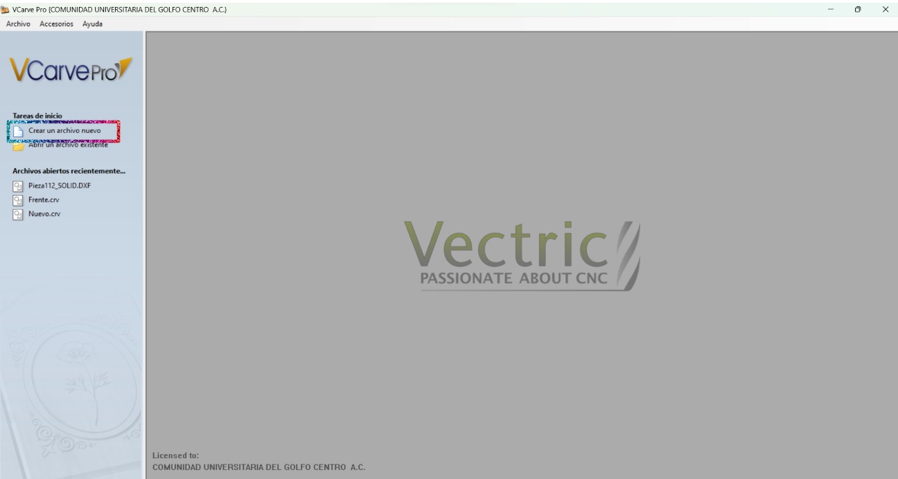
I did the toolpath with VCarve, which is a software that lets the user create the toolpath from a 2D image. This software has different machining operations, such as profile, digging, drilling, and coating. It also allows to save the path for many machines and for different tools. The steps I had to do are the following:
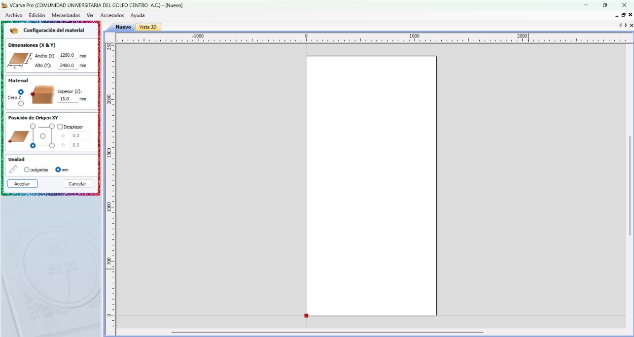
- Create a new file.
- Establish the material configurations (material dimensions, material thickness, XY origin, and units).
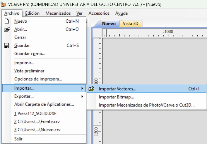
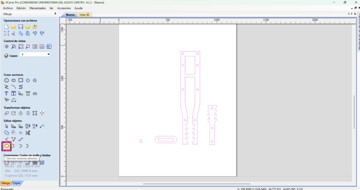
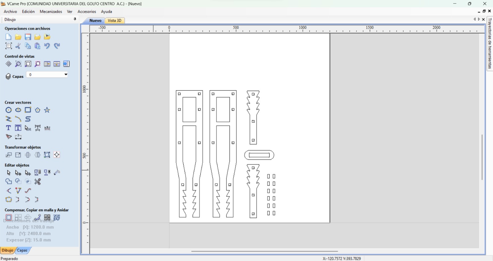
- Import all the required vectors.
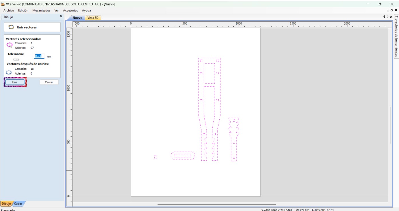
- Select all the vectors and close them.
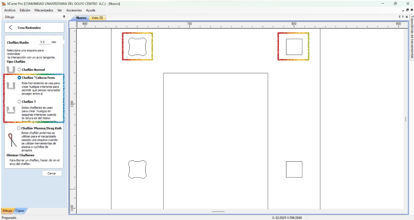
- Place the fillets in order to compensate the tool kerf making sure that the radius is the one from the tool (3.5 mm).
- Create as much copies of each drawing as needed.
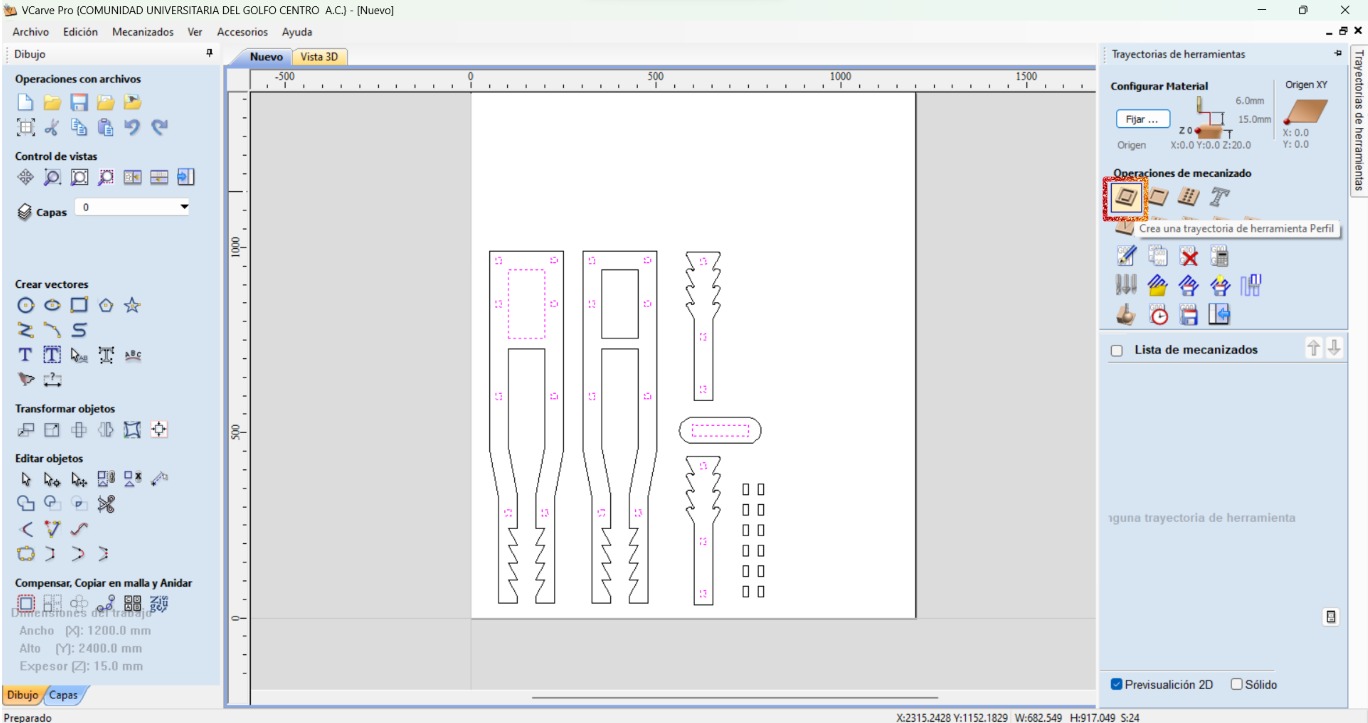
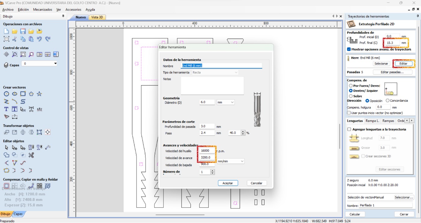
- Select all the internal shapes so that they are cutted first. Then choose the profile operation.
- Adjust the specifications for the internal cuts: final depth, the correct tool, spindle speed, feed speed, and how it will cut.
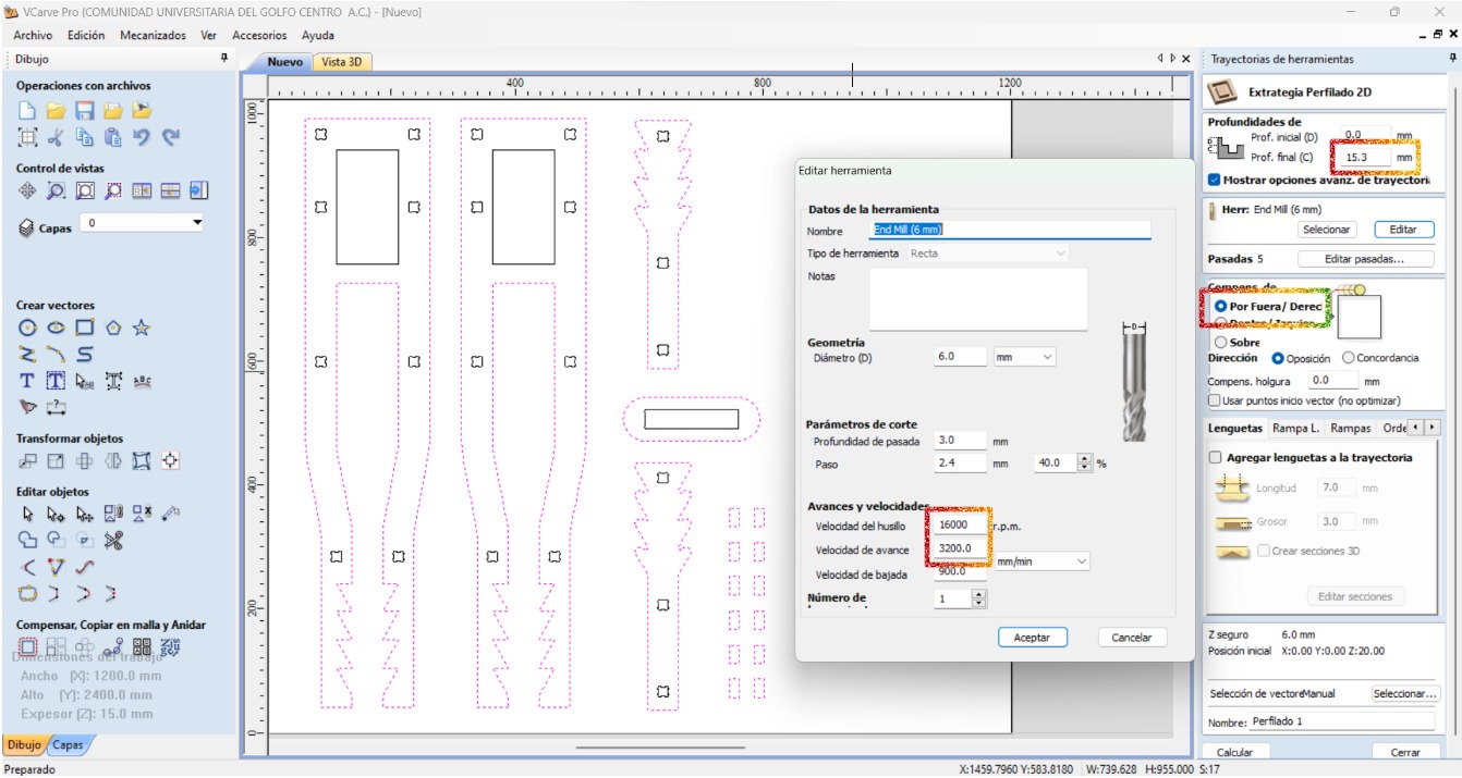
- Select the rest of the shapes to make their profile operation making sure to adjust the specifications.
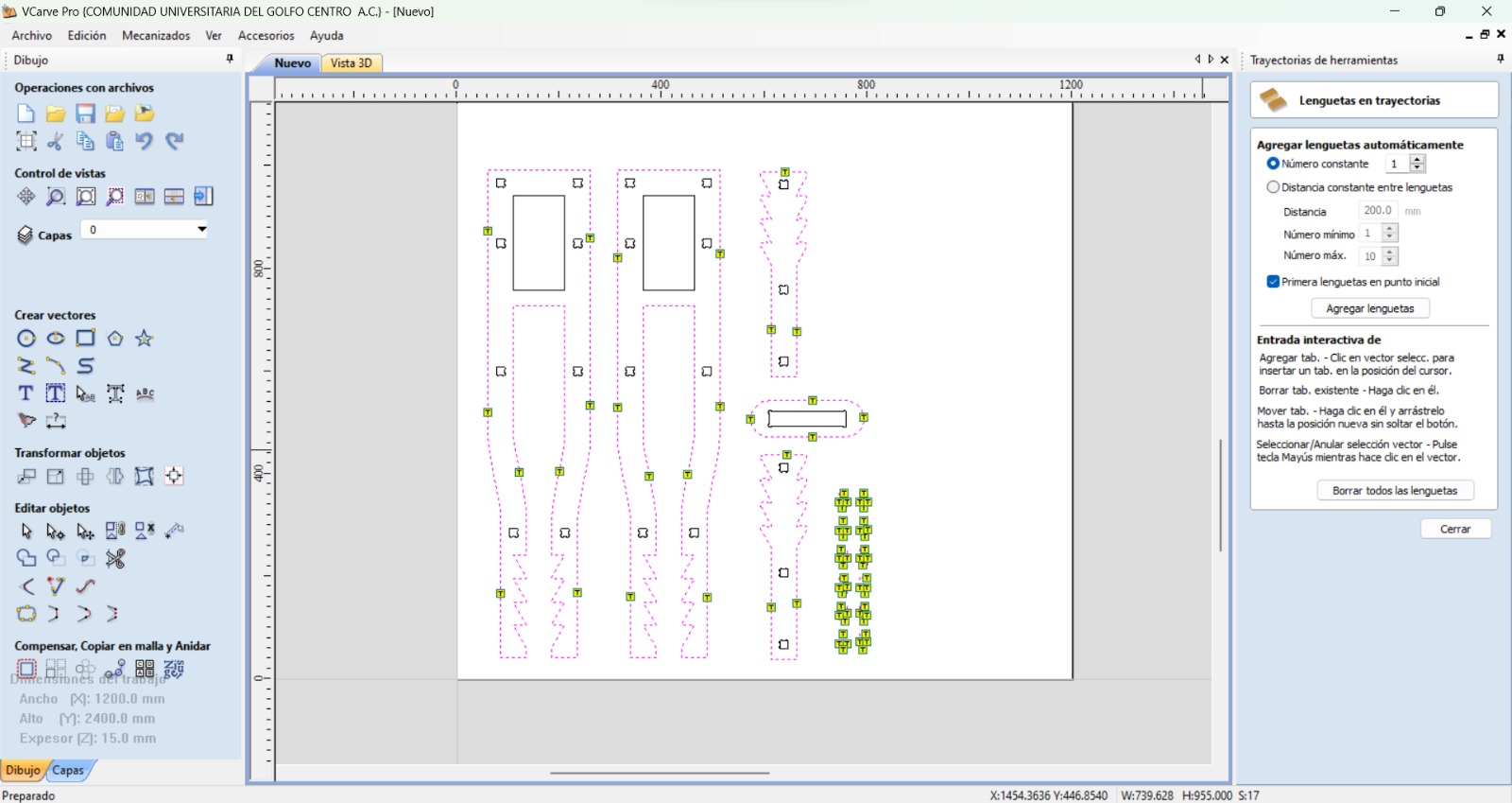
- Place tabs to prevent the pieces from moving while the process is going on.
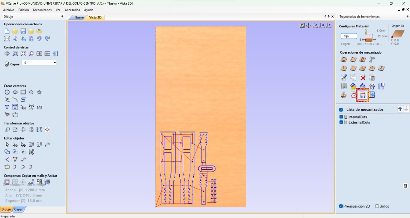
- Save the toolpath.
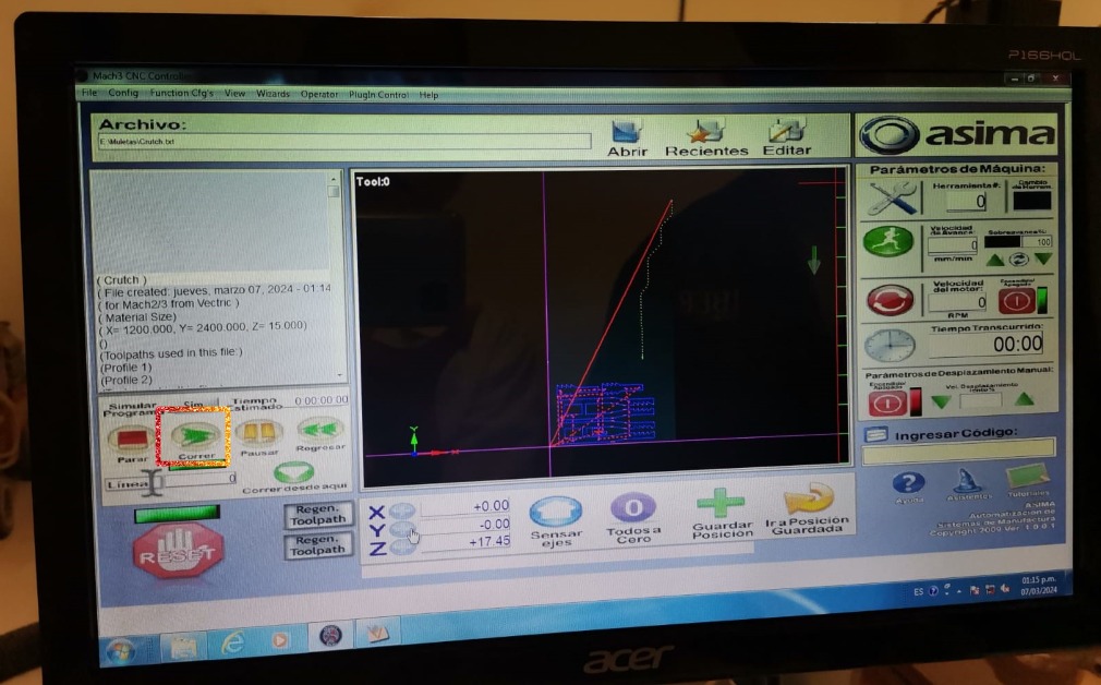
CNC Router
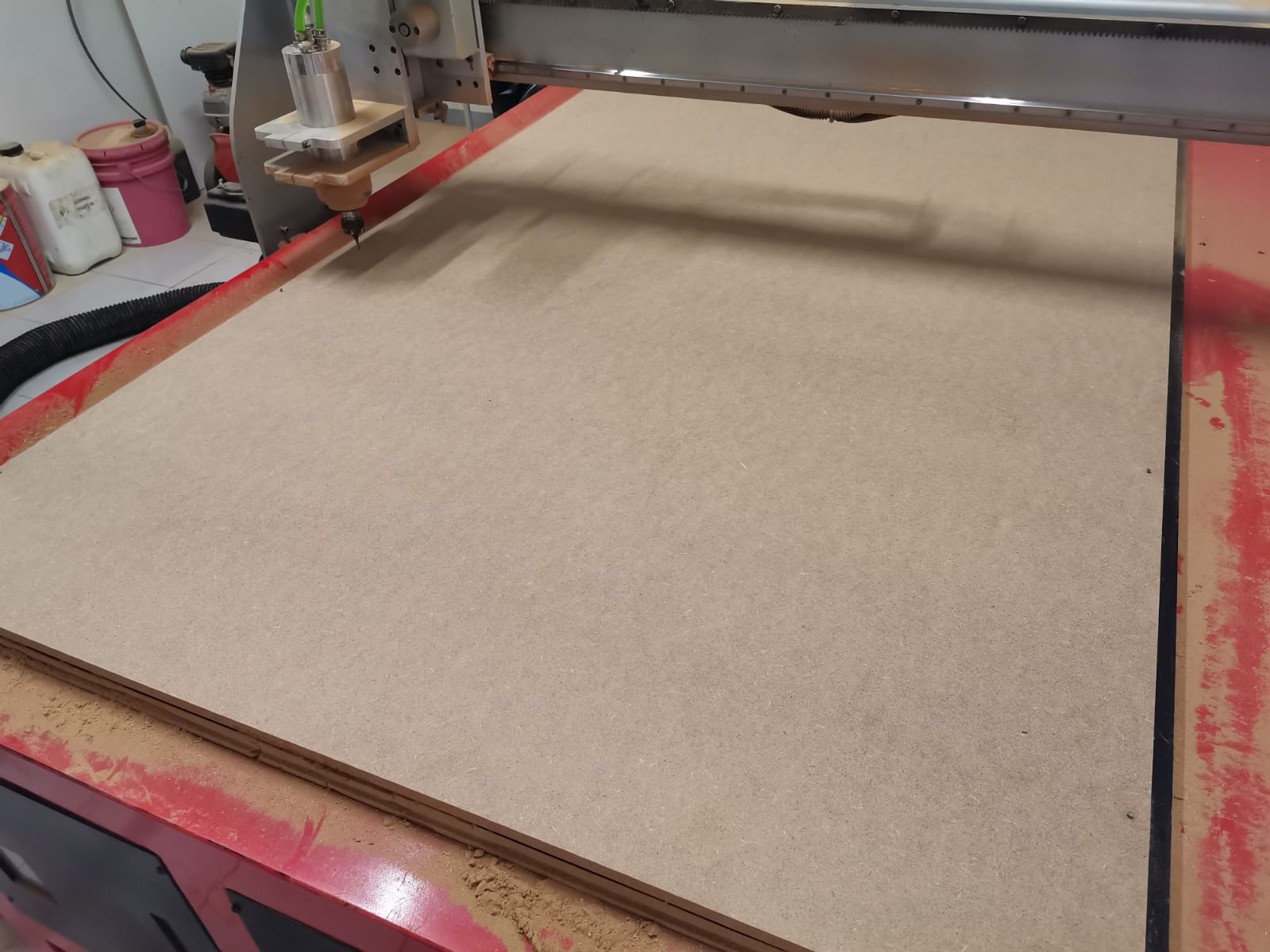
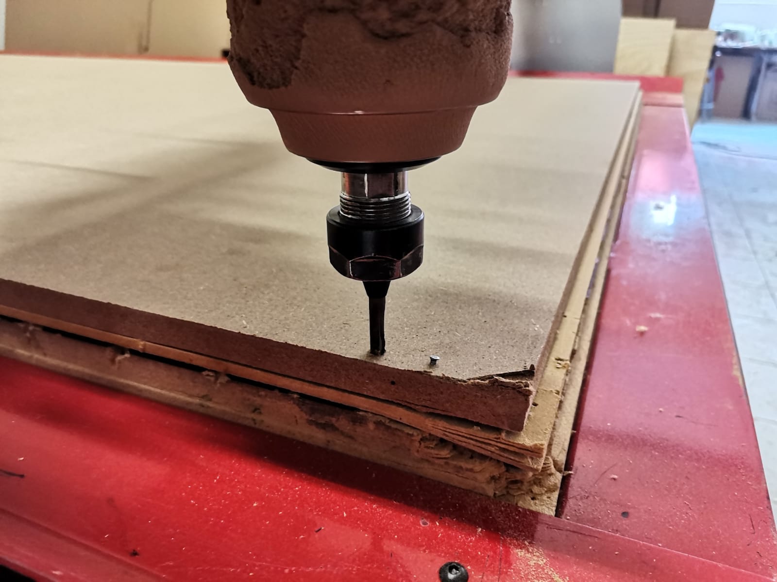
To cut in the router I used a 15mm-width MDF and followed the next steps:
- Nail the MDF to the machine bed.
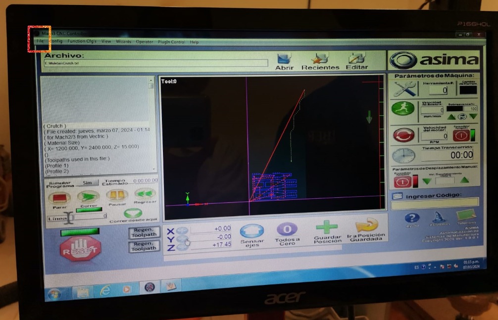
- Import the G-code file into the software already installed in the machine computer y clicking on "File" and then "Import".
- Set the origin for each axis using: shift + arrows and shift + Av/Re Pag.
- Click on the "Run" button.
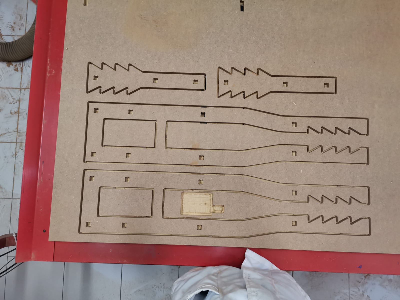
Final Result
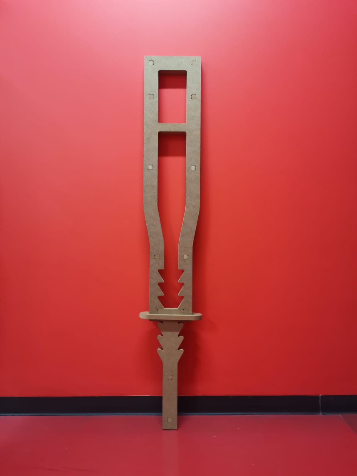
In the final result I had a problem, because I forgot to put some dogbones in the bottom and the adjustable part of the crutch piece, so it didn't assemble well. However, I solved the problem by rounding the corners of the bottom piece. The pieces were cutted like this:
Crutch frame:
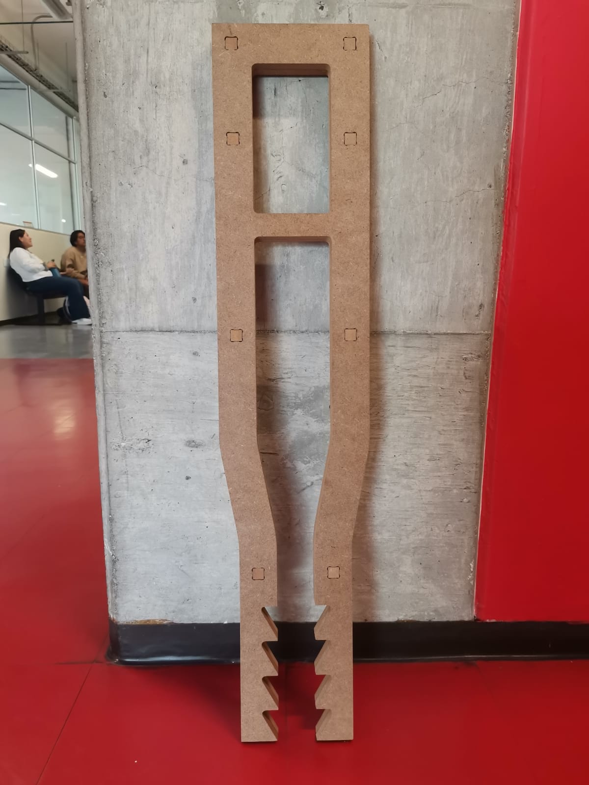
Crutch bottom:
Crutch union:
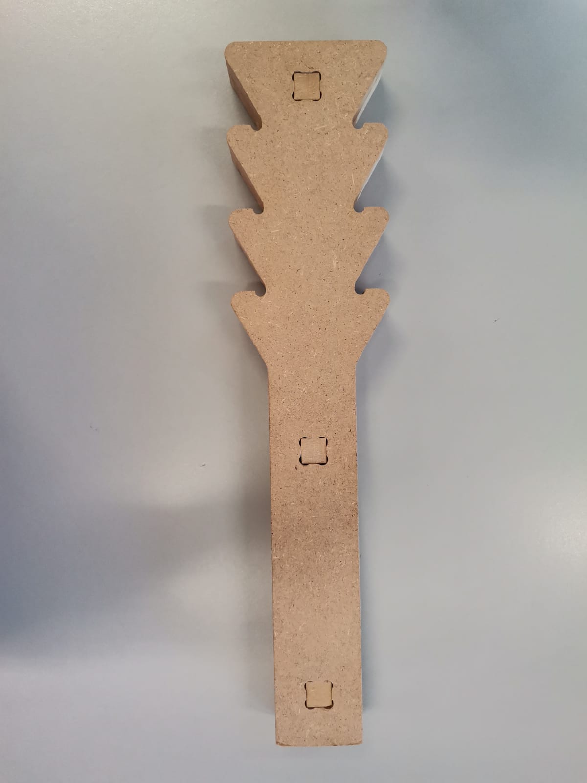
Also, the saw-like structure allows the crutch to have adjustable height:
Minimum height:
Medium height:
Maximum height:
Files
SolidWorks Files (.SLDPRT and .SLDASM)
- Crutch frame (.SLDPRT)
- Crutch adjustable bottom (.SLDPRT)
- Crutch union (.SLDPRT)
- Crutch joints (.SLDPRT)
- Complete crutch (.SLDASM)