13. Networking and communications
This week I worked on defining my final project idea and started to getting used to the documentation process.
Here you will find the group assignment with a little more information about the Networking and communications.
Research
I2C
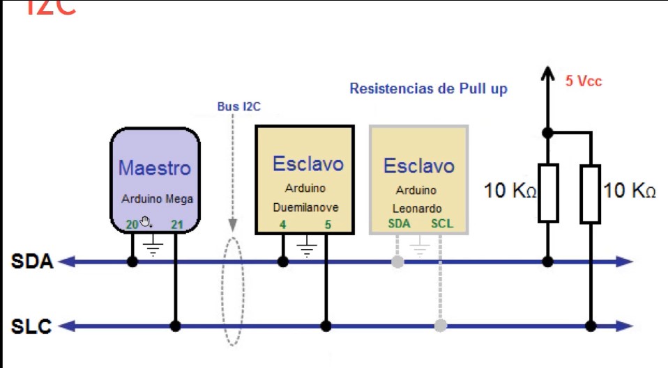
The I2C communication, which stands for Inter-Integrated Circuit, is a serial communication protocol that enables data transfer between devices using only two wires: one for data transmission (SDA) and another for signal synchronization (SCL). In I2C communication, devices are connected on a shared bus, where each device has a unique 7-bit address. This allows communication between multiple devices on the same network without address conflicts.
The basic operation of I2C communication involves a master and one or more slaves. The master initiates and controls data transmissions, while the slaves respond to the master's requests. The master sends a start signal followed by the address of the slave it wishes to communicate with, followed by the data it wants to transmit or request.
UART
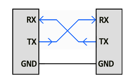
UART (Universal Asynchronous Receiver-Transmitter) communication is a serial communication protocol that allows data transmission between electronic devices. It uses two main pins for data transmission:
- TX (Transmit): This pin is used to send data from the device. It is the line through which data exits the device to another device.
- RX (Receive): This pin is used to receive data on the device. It is the line through which data enters the device from another device.
The TX pin of one device is connected to the RX pin of the other device and vice versa, allowing bidirectional communication. UART communication is asynchronous, meaning it does not require a shared clock signal; instead, devices agree on a transmission speed (baud rate) and use start and stop bits to synchronize data transmission.
In my case, I could not use this communication because the Attiny85 does not have these pins.
SPI
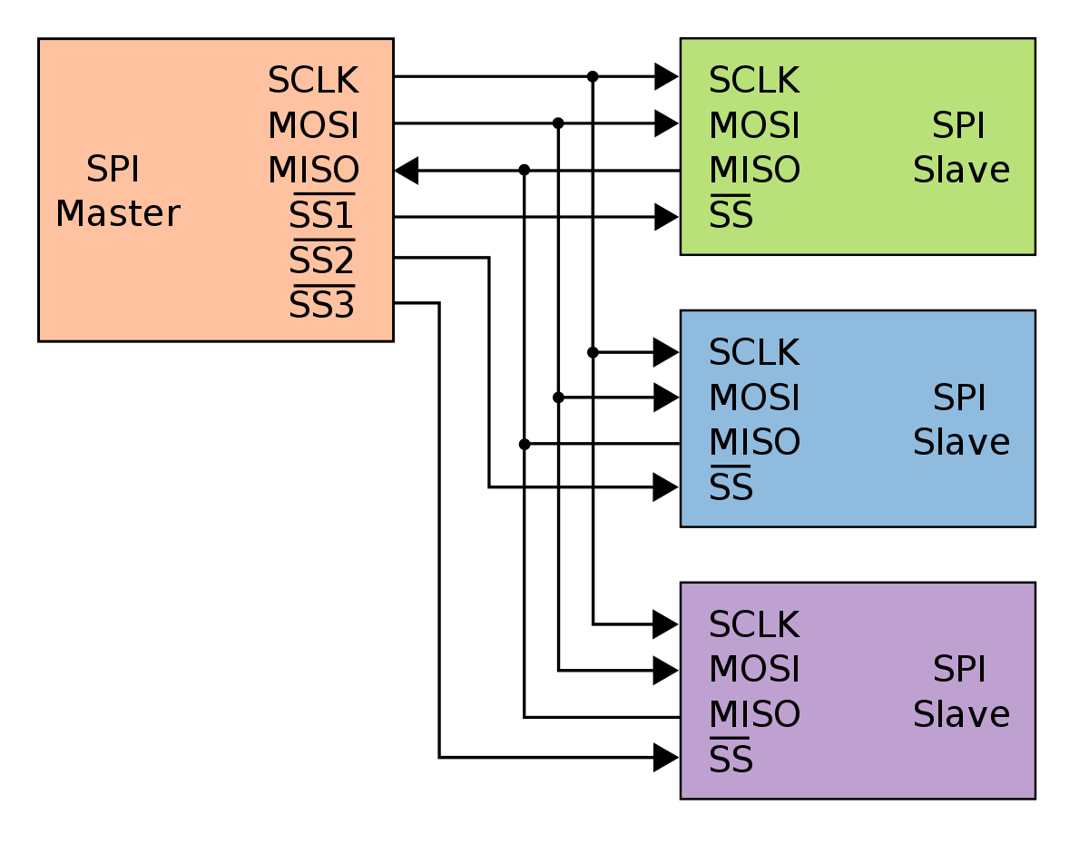
SPI (Serial Peripheral Interface) is a synchronous serial communication protocol used for high-speed communication between microcontrollers and other peripheral devices like sensors, memory, and other integrated circuits. Unlike UART, SPI requires a shared clock signal. It uses four main lines:
- MOSI (Master Out Slave In): Data line used to send data from the master to the slave
- MISO (Master In Slave Out): Data line used to send data from the slave to the master.
- SCLK (Serial Clock): Clock signal generated by the master to synchronize data transmission.
- SS/CS (Slave Select/Chip Select): Line used by the master to select the slave it wants to communicate with. This pin is activated (usually pulled low) to enable communication with a specific slave.
SPI allows for fast and efficient communication with multiple devices in a master-slave configuration, where one master device controls several slave devices.
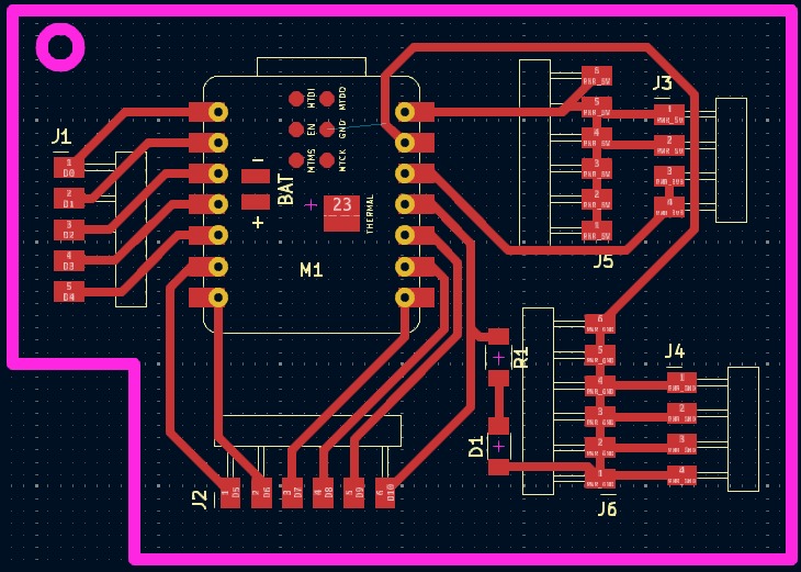
PCB creation XIAO ESP32C3
This week of communication between microcontrollers, I had to make one more PCB, and since I'll be using the Xiao ESP32C3 for my final project, I took the opportunity to make my PCB.
To be able to create my PCB, I created the following files where you can see my new PCB. xiao esp32-Margin is for the margin and cutting it from the copper board, and the file xiao esp32-F_Cu is for the traces of the tracks.
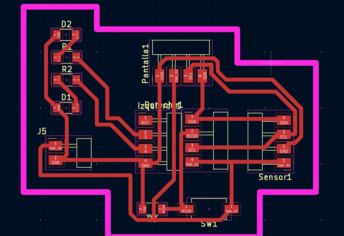
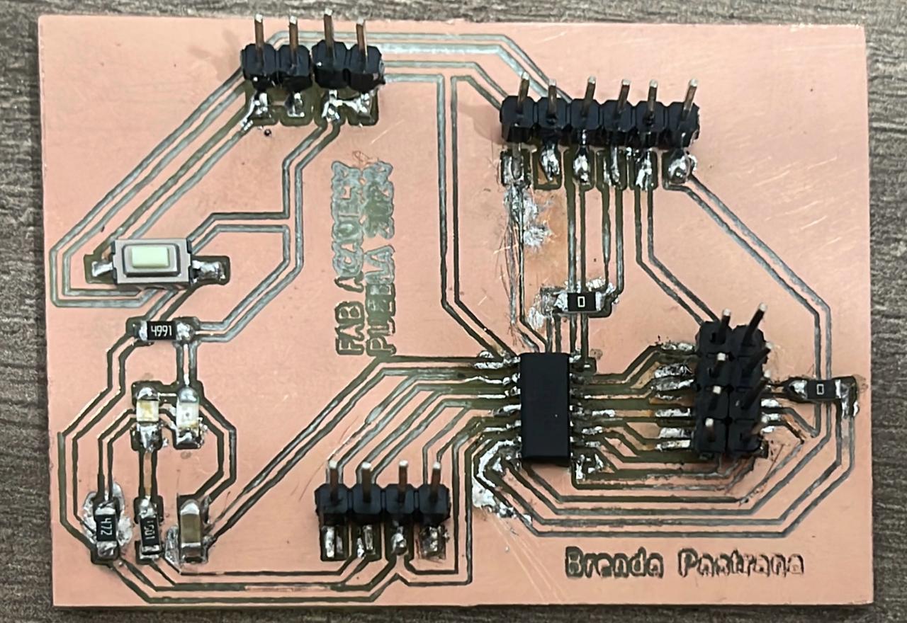
PCB creation ATTINY85
Due to problems this week with establishing communication and suspecting that it might be related to my PCB with the XIAORP2040, I had to create another PCB and used an ATTINY85 instead.
To be able to create my PCB, I created the following files where you can see my new PCB. attiny85-Margin is for the margin and cutting it from the copper board, and the file attiny85-F_Cu is for the traces of the tracks.
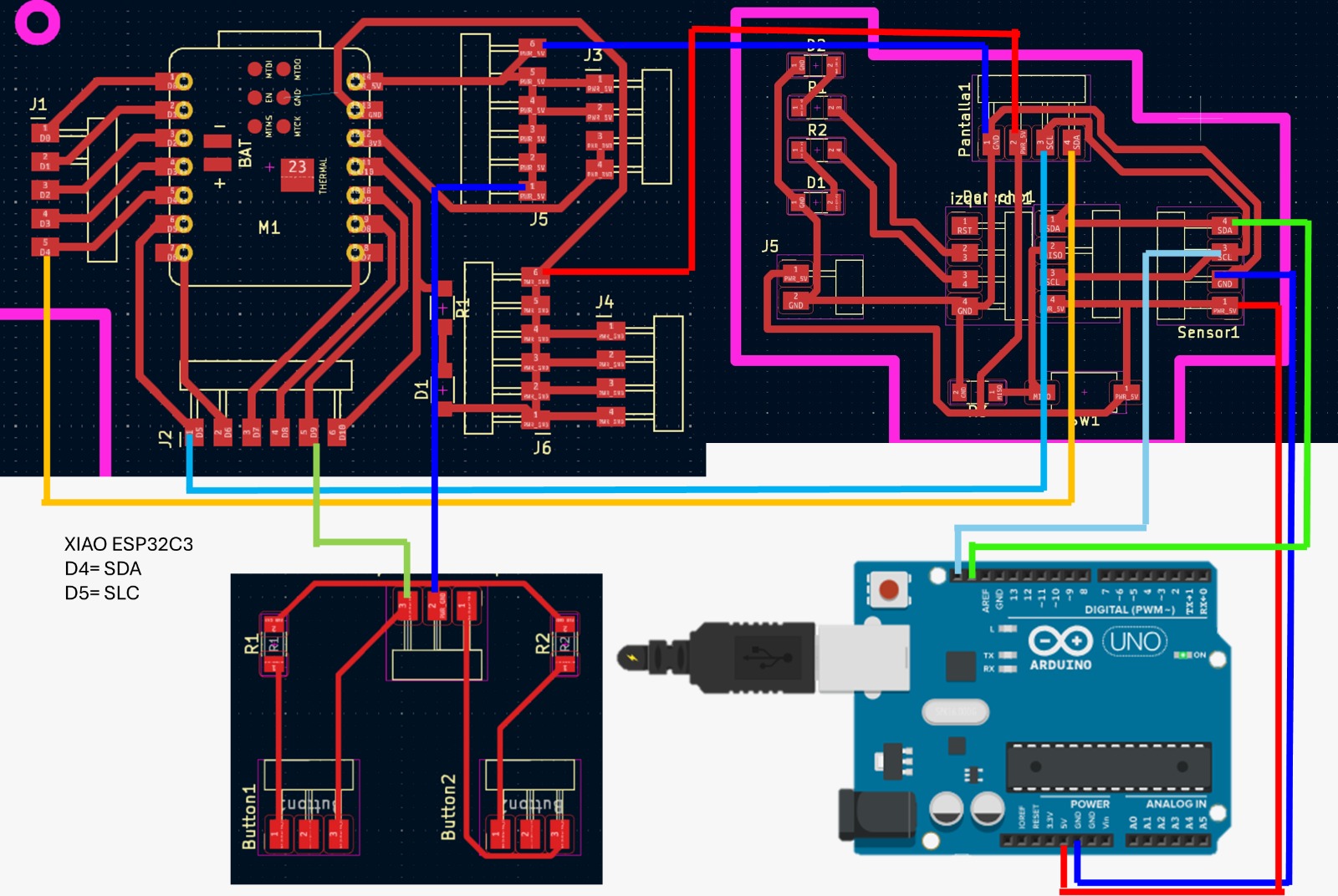
Programming
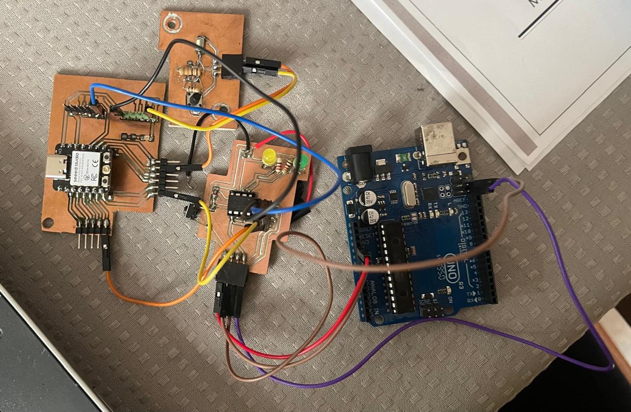
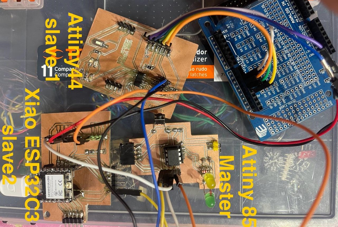
For the programming part, it is important to follow the following setup where I used the Xiao ESP32C3 microcontroller as the master, the Attiny 85 as slave 1, and the Arduino UNO as slave 2.
It is important to upload the code to each microcontroller one by one to avoid confusion. The way of programming the Attiny 85 in this case was different from what I'm used to. From my experience, the Attiny 85 is first programmed using the Arduino UNO as the programmer. Once that is done, it is placed in the circuit where it will perform its function, connecting only the power and ground wires. That is, first it will be placed on a breadboard as follows:
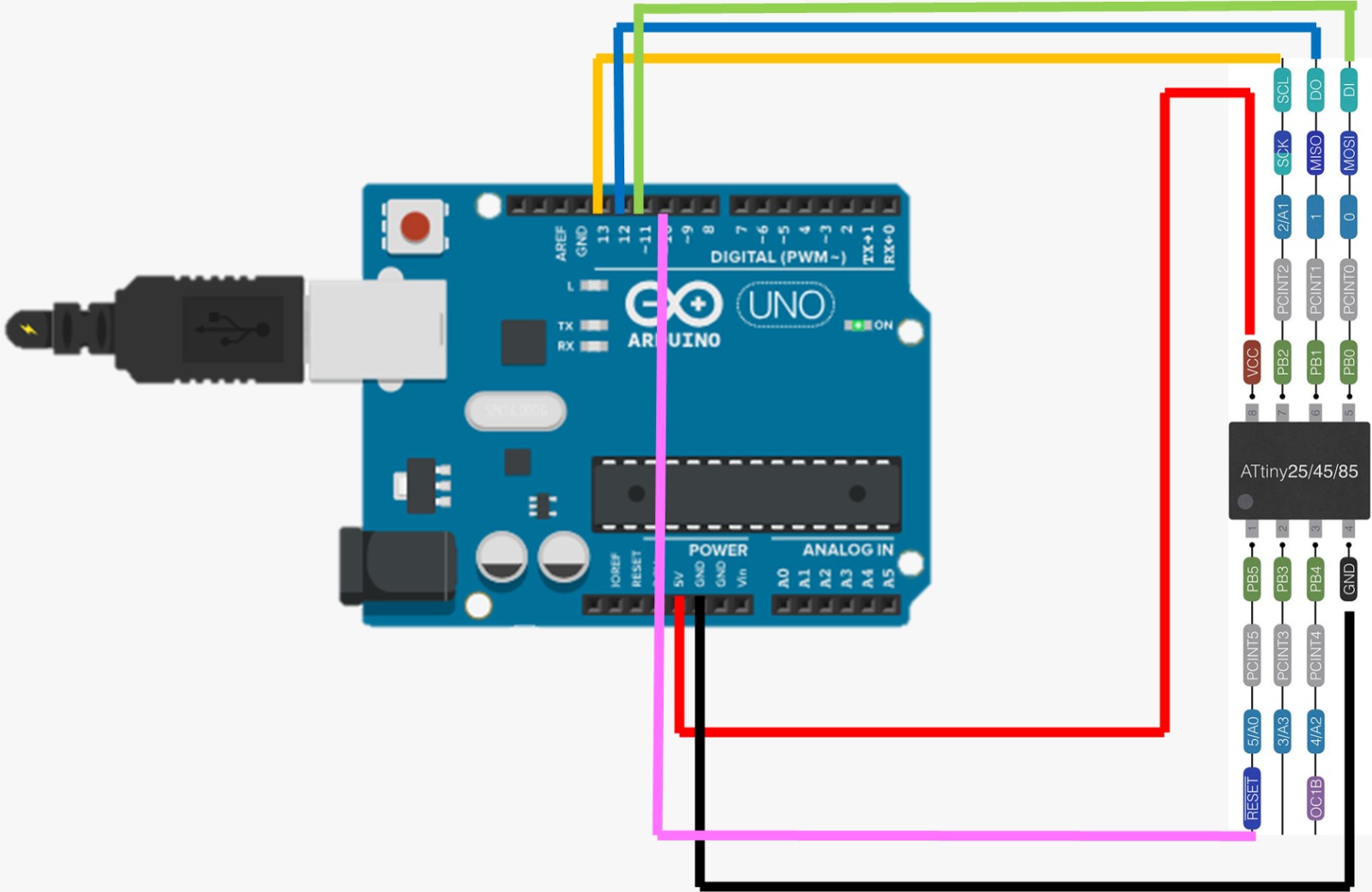
Once the desired code is loaded, it is placed on the PCB. Now, it just remains to ensure that each microcontroller is connected correctly and has its corresponding code.
For the coding part, I will set up a serial communication between them, where the master must have the names of the slaves to know exactly to whom it is sending information and to send a number indicating what needs to be done. On the other hand, the slaves need to include their name in the part that indicates Wire.begin(#) in their code, and specify what they will do if the master calls them and what they will do if they are not being called.
Video
In the video, you can see how, through the button connected to the Xiao ESP32C3, when the button is not pressed, the green LED on the Attiny85 remains on and the Blink LED on the Arduino UNO stays off. When the button is pressed, the Blink LED on the Arduino UNO turns on and off, and the LED on the Attiny85 turns off.
Problems
This week, to be honest, has been the most complicated one I've had so far. Mainly because when trying to set up the communication with my Xiao RP2040, I connected 2 resistors where it indicated they should go in SDA and SCL, but in doing so, the GND made contact with the 3V, causing my microcontroller to die. This was the one I planned to use as the master since that PCB had a button. Later, I made a PCB with an attiny 85, which did have a button, and another PCB with a Xiao ESP32C3. The problem with this one was that it didn't have an implemented button, so I decided to make the attiny 85 the master and the attiny 44 and the Xiao ESP32C3 the slaves. Despite several attempts, it didn't work.
After several weeks, I decided to try again, but this time I made a PCB to include buttons. This way, the Xiao ESP32C3 would be the master and the attiny 85 and 44 the slaves. The issue then was that when I first connected the Xiao ESP32C3 to the attiny 44, upon powering everything up, the attiny 44 smoked and heated up, so I immediately disconnected everything. After testing the attiny 44 again with a simple code to turn an LED on and off and seeing it worked, I was relieved, but I didn't want to keep trying with it.
So, finally, my last option was to make the Xiao ESP32C3 the master, the attiny 85 a slave, and an Arduino UNO a slave. With this setup, everything worked fine.
Conclusion
I focused on inter-microcontroller communication to develop an integrated electronic system. I learned to use communication protocols like I2C and UART to establish reliable connections between devices. This process allowed me to understand how to coordinate and synchronize multiple electronic components to work together seamlessly. The experience was pivotal in enhancing my skills in hardware integration and deepening my understanding of the importance of efficient communication in designing complex electronic systems.
Files
- master.ino/a>
- slave1.ino
- slave2.ino
- Xiao esp32-F_Cu
- Xiao esp32-Margin
- attiny85-F_Cu
- attiny85-Margin
Programming
PCB XIAO ESP32C3
PCB ATTINY85