Input Devices
Throughout this week we will work with input devices, in my case I will use a water level sensor, I chose this specific sensor as it is one that I will use for my final project. The purpose of this sensor is that when it reaches a certain water limit, it sends a signal, in this case that an LED is lit.
This week’s group assignment is as follows: Probe an input device(s)'s analog levels and digital signals and document your work on the group work page and reflect on your individual page what you learned.
Group assignment week 11
Moreover, the individual allocation is as follows: Measure something: add a sensor to a microcontroller board that you have designed and read it.
what is an input device?
An input device is any hardware component that allows users to input data into a computer system. These devices are used to enter information or commands for processing by the computer. Common examples of input devices include keyboards, mice, touchscreens, trackpads, scanners, digital cameras, microphones, and joysticks. Each input device serves a specific purpose and enables users to interact with the computer in various ways.
In addition to the aforementioned input devices, sensors are another type of input device that detect and convert physical or chemical phenomena into electrical or digital signals that a computer can understand and process. In the context of a water level sensor, this device is used to measure and monitor the water level in a tank, reservoir, or any other container. It provides information about whether the water level is above or below a certain threshold, which can be useful in applications such as flood control, monitoring water resources, or automating irrigation systems.
PCB design
As with the other assignments that include electronics, I will use Kicad to design my board. The design of this new board is quite simple and the components are few. These are the components I’m going to be using in this mapping.
Components
| 1 | Led |
| 1 | Resistor 220K |
| 1 | Water level sensor |
| 3 | Pin |
Note: This board is going to be connected to the board I made in my Week 8
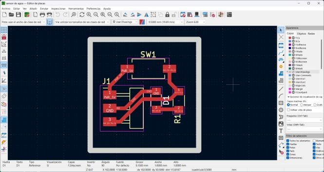
Knowing already the components that I will be using for this assignment, I will make based on this the circuit schematic design and later the PCB design. This is the design I’ll be using.

Board cutting
This time I couldn’t use the Roland SRM 20 for time, so I had to use the Lunyee
LUNYEE 3018 PRO
- Operational Travels in X, Y, and Z: 300 mm (X) × 180 mm (Y) × 80 mm (Z)
- Loadable Workpiece Weight: [Data not provided]
- Operation Speed: 2000 mm/min
- Software Resolution: 0.025 mm/step
- Mechanical Resolution: 0.025 mm/step
- Spindle Rotation Speed: 12000 RPM
- Interface: USB
- Operational Noise: [Data not provided]
- External Dimensions: 7.09"W x 11.81"H
- Weight: 11 kg
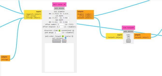
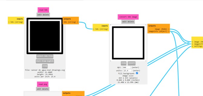
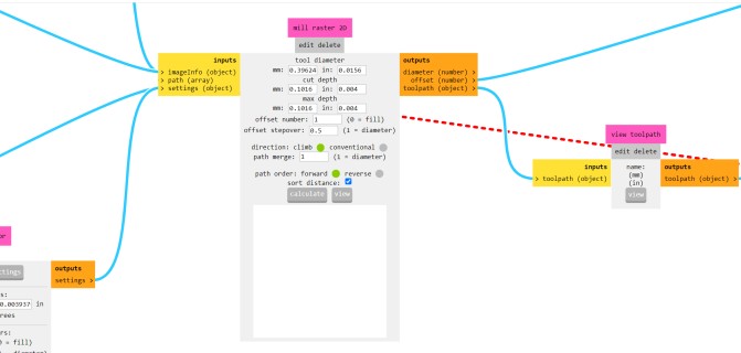
Before I start cutting I need to put the file in . SVG so I can put it in Modsproject. Being a different milling machine than the one I have used during past assignments the modules are different. Below I will show the modules that change and the values that have to be assigned.
Traces
1.- File in .SVG

2.- SET PCB DEFAULTS (10 mill)
.jpg)
3.- MILL RASTER 2D
Cut
1.- File in .SVG
2.- SET PCB DEFAULTS (10 mill)
3.- MILL RASTER 2D
Tools
.jpg)
Cut and traces tools
This is the milling machine working
Soldering
Having already cut the board, it is time to solder the components to the board, being a small board the number of components were not many. For this reason, this step was faster. This is the final result of mi soldering.
.jpg)
Problem
As I started programming the board to test its functionality, I realized that the water sensor I had was not working correctly. For this reason, I had to purchase a different water sensor to complete this task.
Water sensor T1592
- Sensor Type: Analog
- Minimum Supply Voltage: 3V
- Maximum Supply Voltage: 5V
- Working Current: Less than 20 mA
- Detection Area: 40mm x 16mm
- Production Process: Double-sided FR4 HASL
- Minimum Operating Temperature: 10°C
- Maximum Operating Temperature: 30°C
- Humidity: 10% - 90% non-condensing
- Dimensions: 65mm x 20mm x 8mm
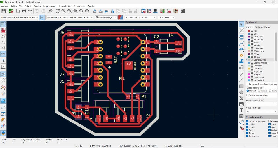
The connections for these pins are as follows: Voltage, Ground, and Signal. Just as I did during the output devices week, I will use the board I created for my final project since it will use this same water sensor. This is the pinout of the board:
.jpg)
.jpg)
Programming
code #1
This code reads the analog value from a water sensor connected to pin A0 and prints a message to the serial monitor indicating the water level (Empty, Few water, Good water level, Full) based on the read value. The reading and message update every 5 seconds.
Problems
| Not being able to use the Roland SRM-20 and had to learn to use another milling machine for the first time. | Ask a consultant for help and learn how to use the milling machine that was available. |
| During board traces the tool destroyed a track. | Reduce the number of passes with the help of Modsproject and thus prevent it from destroying another track. |
| First water sensor didn't work. | Use another one. |