Output devices
For this Week 9 of the Fab Academy which is About Output Devices I’m going to have to add an output device to a microcontroller that you’ve designed and program it to do something.
While for group assignment you have to measure the power consumption of an output device and document your work on the group work page and reflect on your individual page what you have learned.
Group assignment week 9
how to determine the power of consumption of an output device?
To calculate the power consumption of an output device using the law of Ohm, we can utilize the formula:
Where:
- P is the power consumption in watts (W).
- V is the voltage in volts (V).
- I is the current in amperes (A).
This formula is derived from Ohm's law, which states that the voltage across a conductor is directly proportional to the current flowing through it, with the proportionality constant being the resistance of the conductor.
New Board
As I did during week 8, I will use KiCad to design my new board, which will serve to control a servo motor and this new board will be connected to the first plate that I soldered in the last week, in that week I used a ATtiny45V.
What is a Servomotor?
A servomotor is a rotary or linear actuator that allows for precise control of angular or linear position, velocity, and acceleration. It is a closed-loop feedback control system, meaning it continually adjusts its position based on feedback from an internal sensor or encoder.
Servomotors are commonly used in various applications that require precise motion control, such as robotics, CNC machines, automated manufacturing, and remote-controlled vehicles.
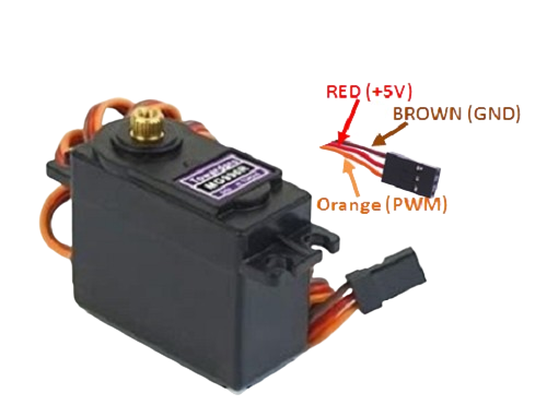
- Voltage range: 4.8V to 7.2V
- Rotation range: 180 degrees
- Temperature: -30°C to 60°C.
- Interface: Analog
Knowing this, these are the components that I will use to design my new board. These components are presented in the following table.
| Qty | Component | Schematic image |
|---|---|---|
| 1 | Pins where the servo motor will be connected | 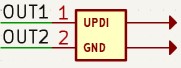 |
| 1 | Voltage and ground pins | 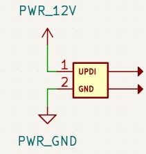 |
| 1 | Transistor | 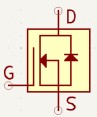 |
| 1 | Signal pins |  |
| 1 | Diode |  |
| 1 | Resistor |  |
Knowing already the components that I was going to use to build the PCB, I had to make sure that the University had them, in case of not having them I would have to buy them in an electronic components store. Fortunately, they had all the components that I was going to use, so I started making the circuit. This is the circuit I created:
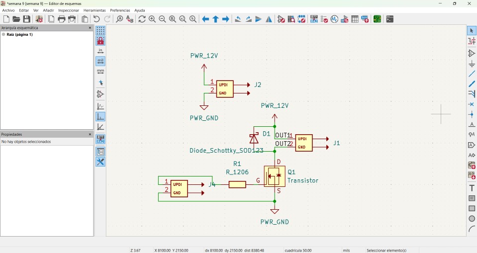
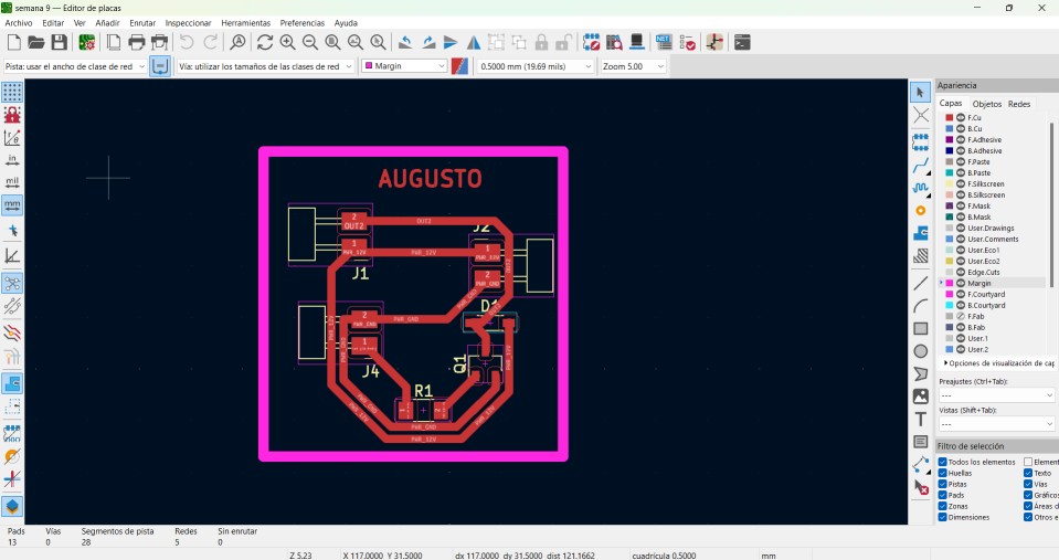
Following exactly the same steps I followed in the previous week of electronic design, this is how the wiring of my PCB was, to this same I customized putting my name to the board.
This is the milling machine cutting
This is the board after the cut
.jpg)
Problems
As you could see, the cut did not go as I wanted, this problem is perhaps because of the configuration I used in modsproject, for this obvious reason I will cut the board again using another configuration.
Re-Design
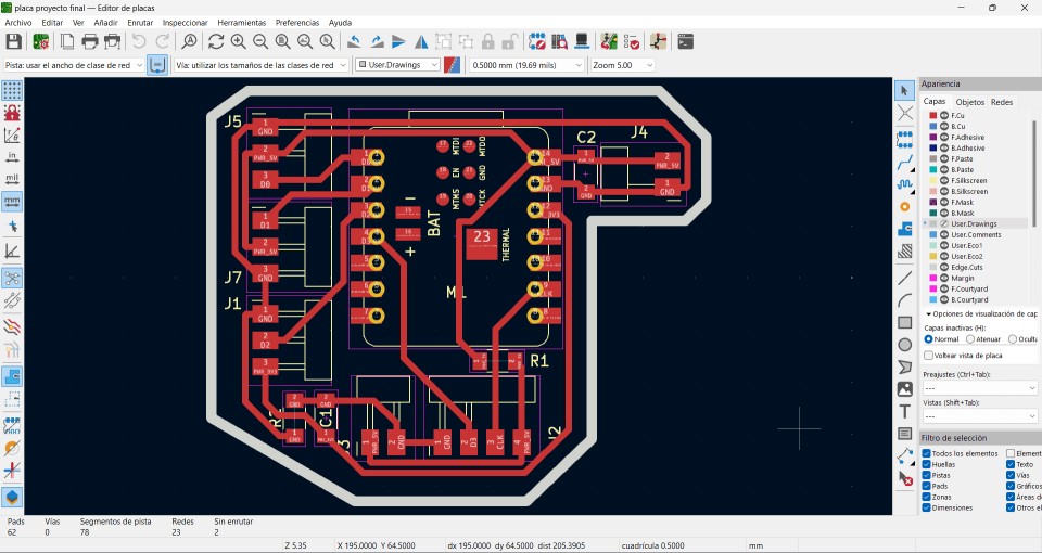
While I was making my board for the final project, I saw the possibility of using this same board for this week's assignment. In the following images, you can see the schematic and PCB designs of the final project board.
.jpg)
.jpg)
According to the PCB diagram, we need to identify the voltage, ground, and PWM pins that we need to use to correctly connect the servo motor.

After checking the output pins of the XIAO ESP32C3, this is the wiring I came up with to move the servo motor with any program.
Programming
CODE #1
This code controls a servo and it attaches the servo to pin D0 and moves it to 180 degrees. In the main loop, it gradually moves the servo from 180 to 90 degrees, pauses for 1 second, then gradually moves it back from 90 to 180 degrees, and pauses for another second.
code #2
This code initializes serial communication at 9600 baud, attaches the servo to pin D0, and initially positions it at 0 degrees. In the loop, it reads angles from the serial monitor and, if they are between 0 and 180 degrees, moves the servo to that angle and prints the angle to the serial monitor, waiting 1 second between readings.
code #3
This code controls two servos and it initializes serial communication at 9600 baud, attaches the first servo to pin `D0` and the second to pin D1, and initially positions both at 0 degrees. In the main loop, it reads a servo number (0 or 1) and an angle from the serial monitor; if the servo number is 0 or 1 and the angle is between 0 and 180 degrees, it moves the corresponding servo to the specified angle and prints the angle to the serial monitor.
Power consumption of an output device
The last video we can see the servomotor MG995, which operates within the voltage range of 4.8V to 7.2V and typically consumes between 0.1A and 0.2A under normal conditions. However, this consumption can significantly increase under maximum load, peaking at up to 2.5A. This wide range of current consumption highlights the critical need for an appropriate voltage source to ensure optimal performance and prevent overload damage.
It is important for the servomotor to be connected to a suitable voltage source to ensure a continuous and stable supply of power, thereby ensuring proper operation of the board. Operating the servomotor within its specified voltage range also guarantees efficiency and optimal performance. Too low a voltage may result in insufficient speed, whereas excessively high voltage can potentially damage the servomotor.
Conclusion
During this week's assignment, I encountered some issues completing it due to a lifted trace that caused a short circuit. However, I eventually found a solution that helped me progress with my final project.