13. networking and communications
This week, I will be using an RFID-RC522. I'm very excited to try this because, for a project I did a few months ago, I needed this exact component. At that time, due to my lack of knowledge, I thought this was hard to find and program. Instead of using this component, I bought a color sensor. Each token had a different color on the bottom, so when it was placed on top of the sensor, it would reproduce the audio linked to that token. It would have been easier to use the RFID-RC522, but I'm excited to be learning about different sensors now, this will definitely help me in the development of my future projects. Additionally you can also find our group page linked.
Types of Communication Between Microcontrollers
- Pins Used: TX (Transmit), RX (Receive)
- Connections: Both TX and RX need to be connected to the same ground.
- Role Configuration: Both devices can initiate communication and are considered equal participants in the communication process.
- Dissadvantage: Typically supports communication between two devices only.
UART (Universal Asynchronous Receiver-Transmitter)
- Pins Used: SCLK (Serial Clock), MOSI (Master Out Slave In), MISO (Master In Slave Out), SS (Slave Select)
- Device Connection: Allows communication with multiple devices by using multiple SS pins.
- Role Configuration: One device controls the clock and data flow (master), while the other devices respond to its instructions (receiver).
- Dissadvantage: Uses more pins compared to UART.
SPI (Serial Peripheral Interface)
- Pins Used: SDA (Serial Data), SCL (Serial Clock)
- Device Connection: Allows multiple devices, identified by unique addresses.
- Role Configuration: One device typically manages the clock and data flow (master, while the other devices respond to its instructions (receiver).
- Advantage:Uses fewer pins than SPI.
I2C (Inter-Integrated Circuit)
RFID and Xiao Esp32-C3
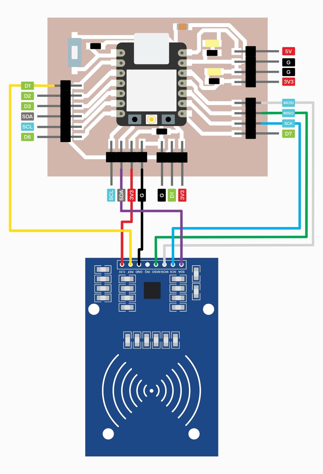
Schematic
I will be using the board I designed for week 9: output devices. Here, you will find a schematic to connect the corresponding pins.
Coding in arduino
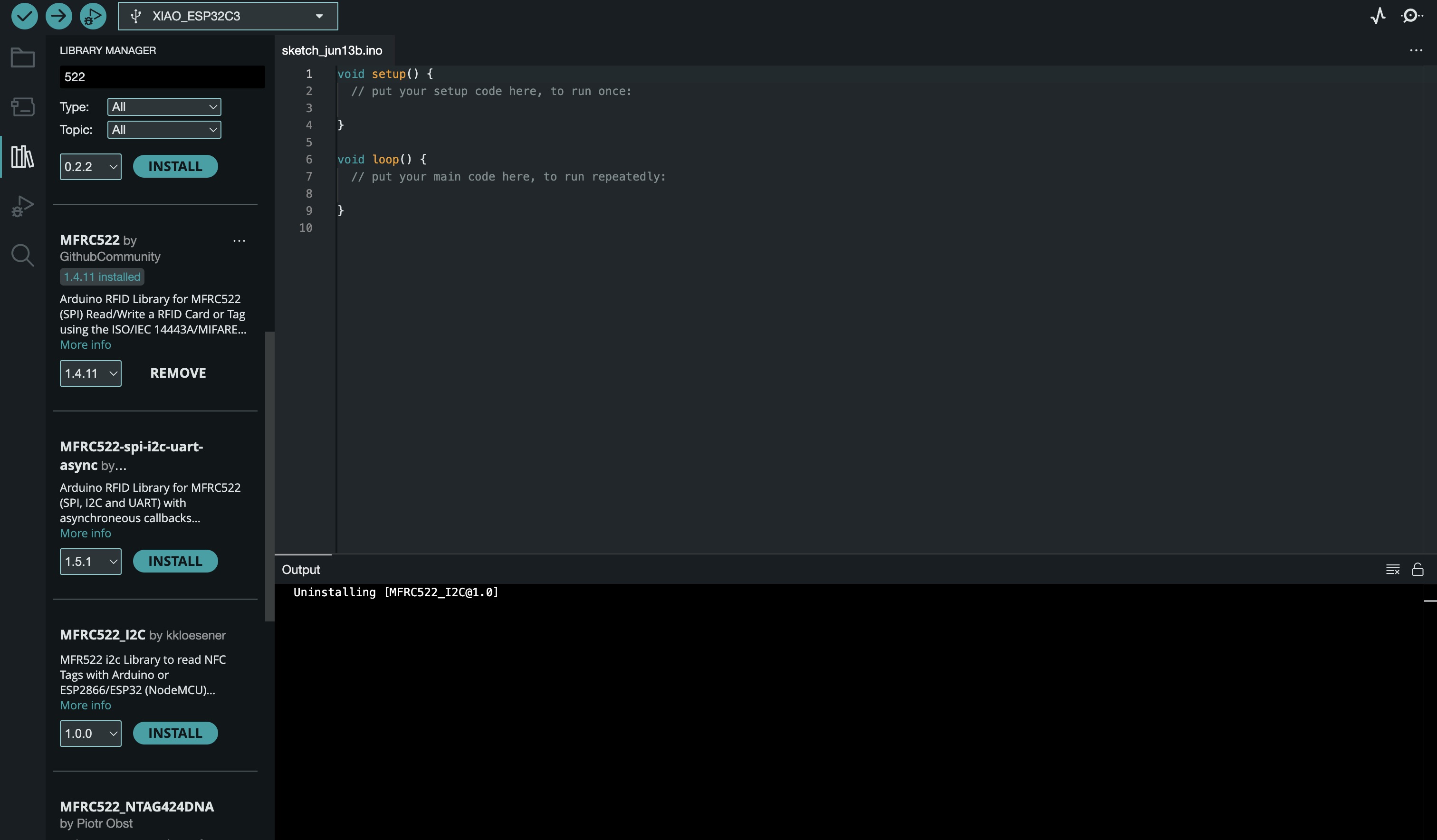
To begin, I had to download a library called 'MFRC522'. I opened 'Library Manager' and typed '522'. You'll see different options, but make sure to download 'MFRC522 by GithubCommunity'.
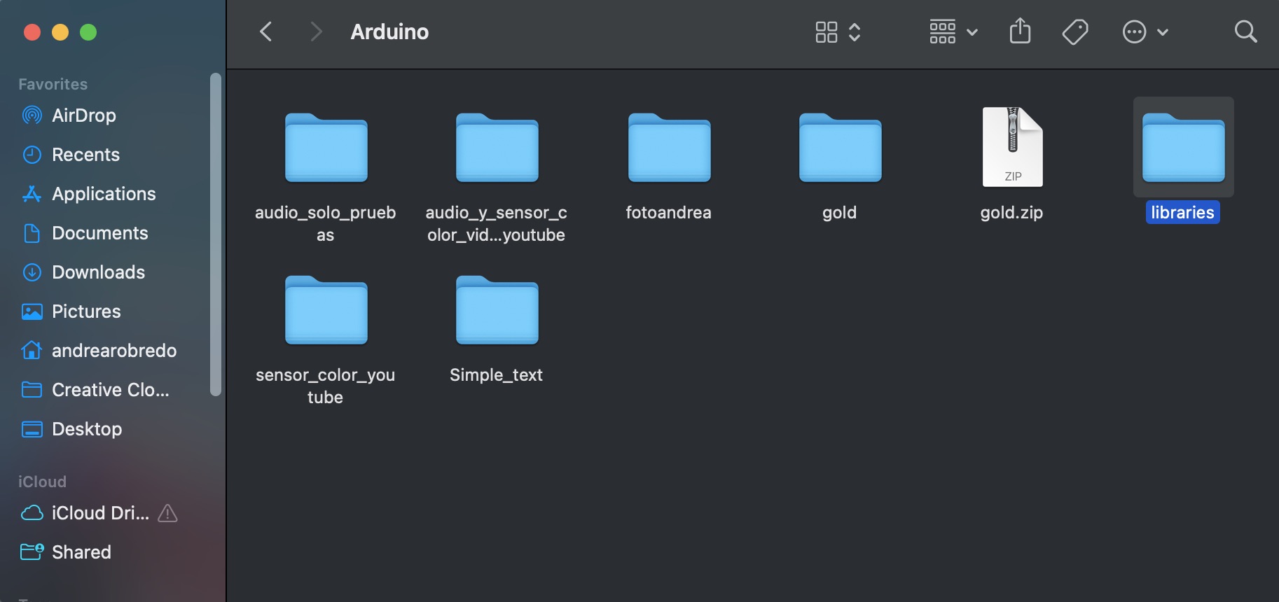
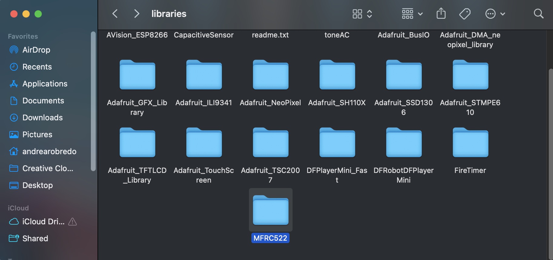
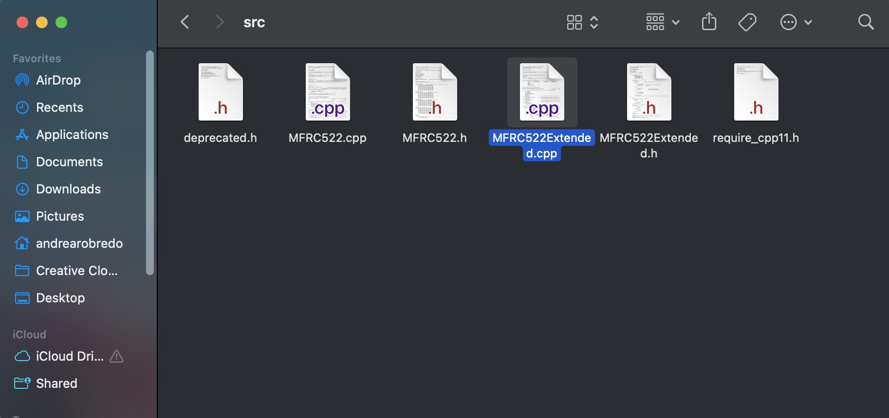
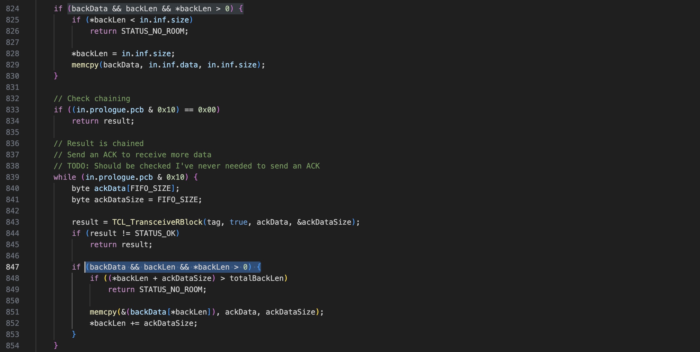
Next, I opened an example from the same library to upload. However, I encountered an error. Not understanding the issue, I asked ChatGPT for help. The problem was related to two lines of code inside the 'MFRC522Extended.cpp' file. To fix this, I navigated to my 'Arduino' folder, then 'libraries', then 'MFRC522', then 'src', and opened the 'MFRC522Extended.cpp' file. I changed lines 824 and 847 from from ‘if (backData && (backLen > 0)) {' to ‘if (backData && backLen && *backLen > 0) {'.
Problems
I encountered several problems to upload the code to my XIAO esp32-3C, what worked for me was the following:
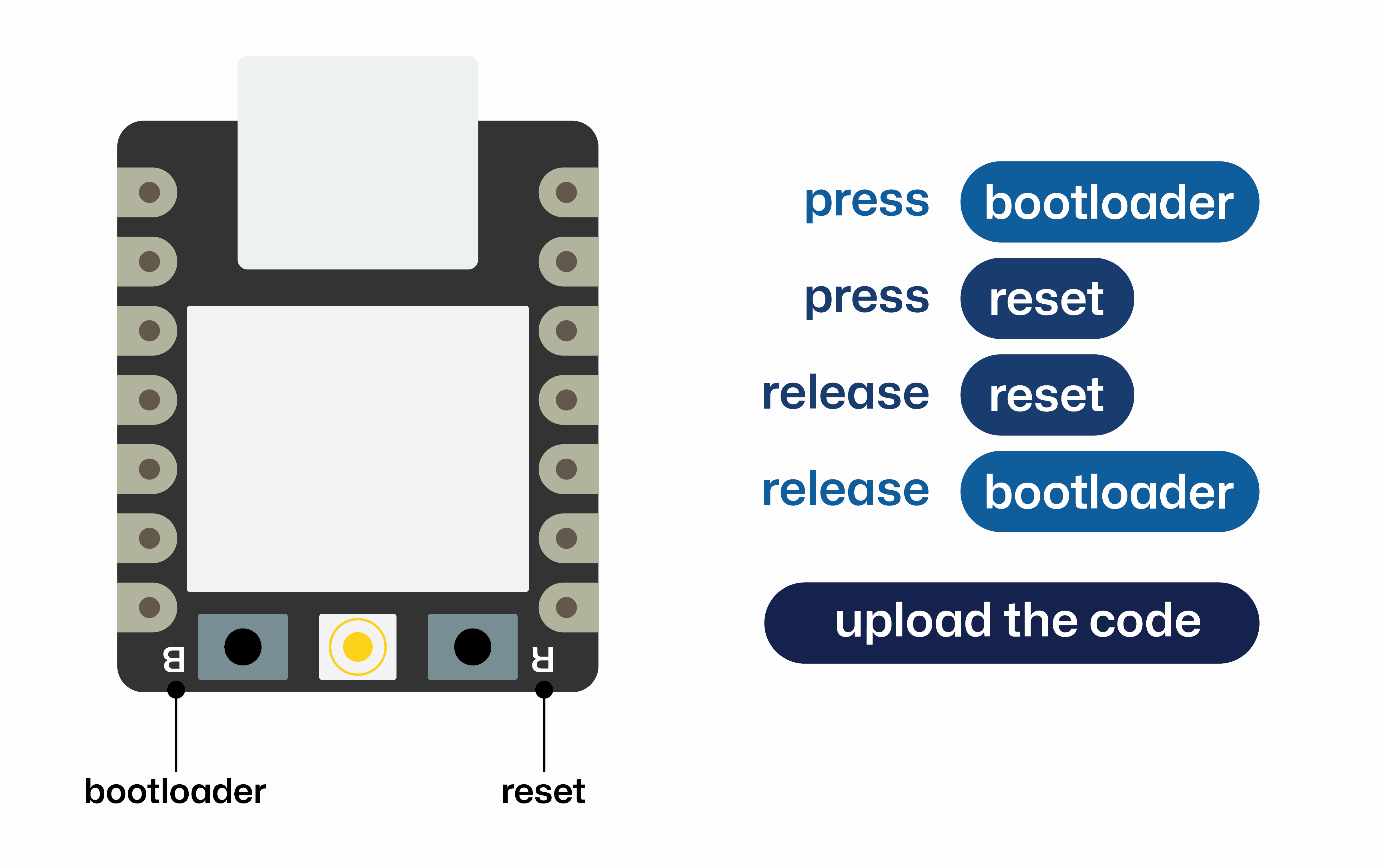
Unfortunately, I wasn't able to get the RFID module to work with any of my microcontrollers. I believe this is due to limitations in the library, which primarily supports Arduino and a few other microcontrollers. However, I did manage to get it working with an Arduino and will continue searching for a solution to make it compatible with my microcontrollers. Since I couldn't complete this week's practice with the RFID and SPI communication, I decided to try I2C communication instead.
I2C communication
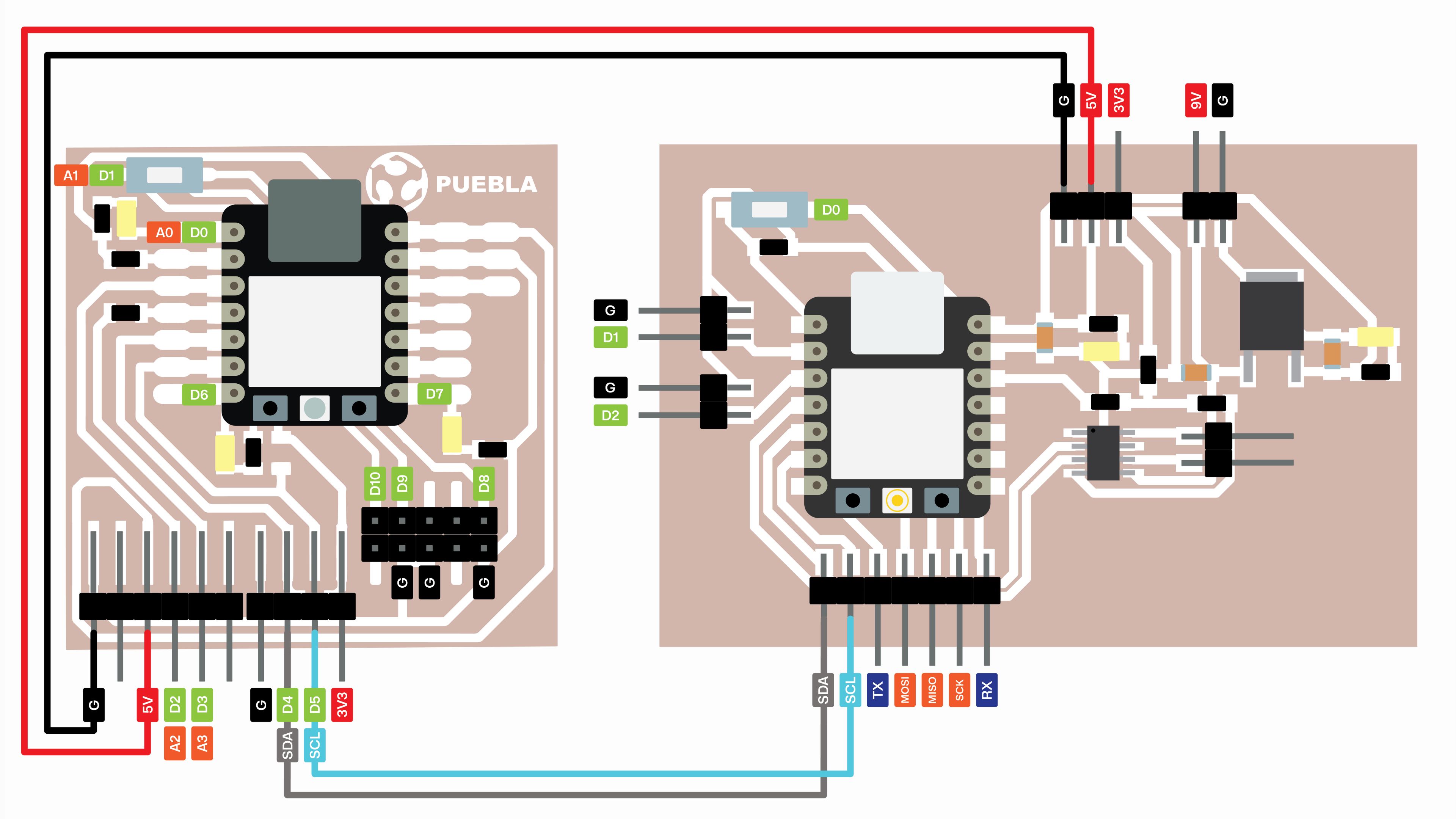
For communicating between two boards, I will be using the board I created for my final project with an ESP32-C3 microcontroller and the Quentores board with an RP2040 microcontroller made in week 4. The ESP32-C3 will function as the master while the RP2040 will be the receiver. I will program a button on the master to blink 3 LEDs on the receiver.
Schematic
The following diagram shows how these boards should be connected.
Coding in arduino
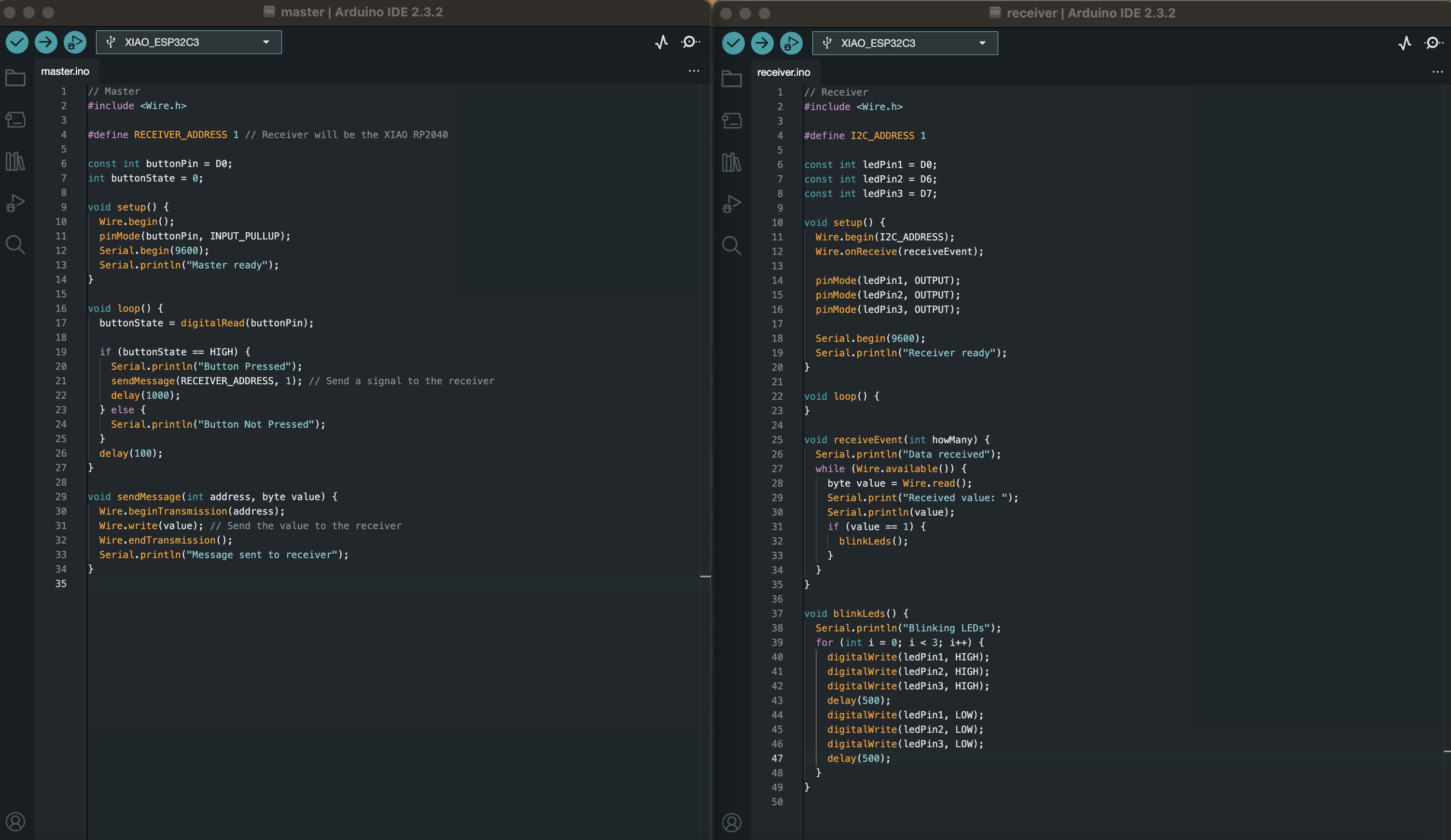
To establish I2C communication between the two boards, it's necessary to develop separate codes for the primary (master) and secondary (receiver) controllers.
In this case, the master board, a XIAO ESP32-C3, reads the state of a button and sends a signal to the receiver, a XIAO RP2040, using the I2C protocol when the button is pressed. The master initializes I2C communication and uses the serial monitor to observe the process. In the main loop, it checks if the button is pressed, and if so, sends a message to the receiver.
The receiver initializes I2C communication with its assigned address and sets up three LED pins as outputs. When the receiver detects incoming I2C data, it reads the value. If the value is 1, it blinks three LEDs three times, providing visual confirmation that the communication was successful.
Final result
Here you can see the final result of the I2C communication.