9. output devices
I had a great time experimenting with the OLED display. Even though I was away from home for spring break in Mexico and couldn't work with my own PCBs, I decided to start exploring the OLED display using an Arduino Uno. I plan to upload these codes to the microcontrollers I've made once I return home. Here you can find our group assigment to know more about output devices.
New board design
I encountered some difficulties while programming the AtTiny 45 with my Mac, so I decided to create a new board using the XIAO ESP32-C3. My goal for this new board is for it to function like an Arduino and be versatile for use in multiple projects.
To start designing the board, I opened up KiCad. To see a more detailed process on how to use this software go back to my week 8: electronic design documentation.
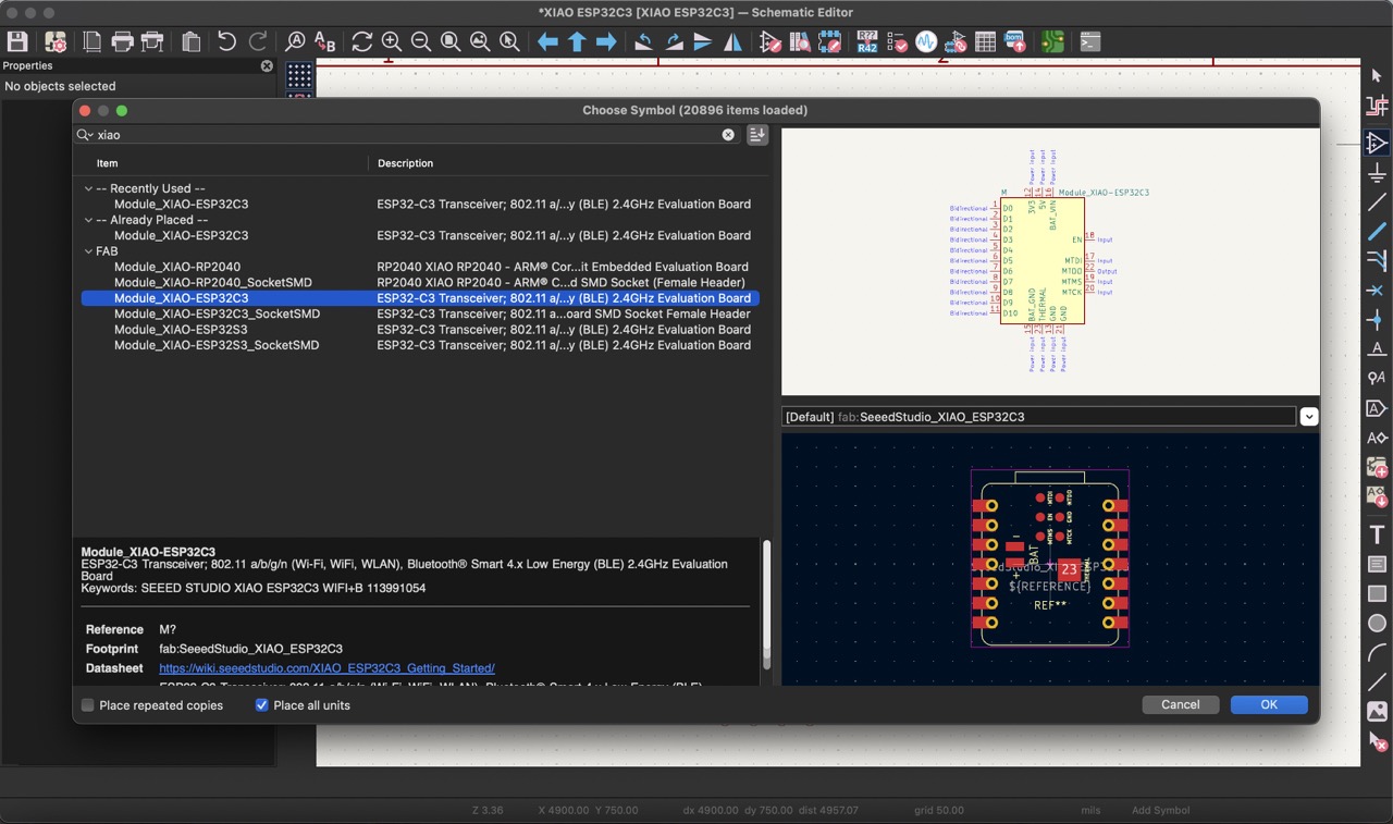
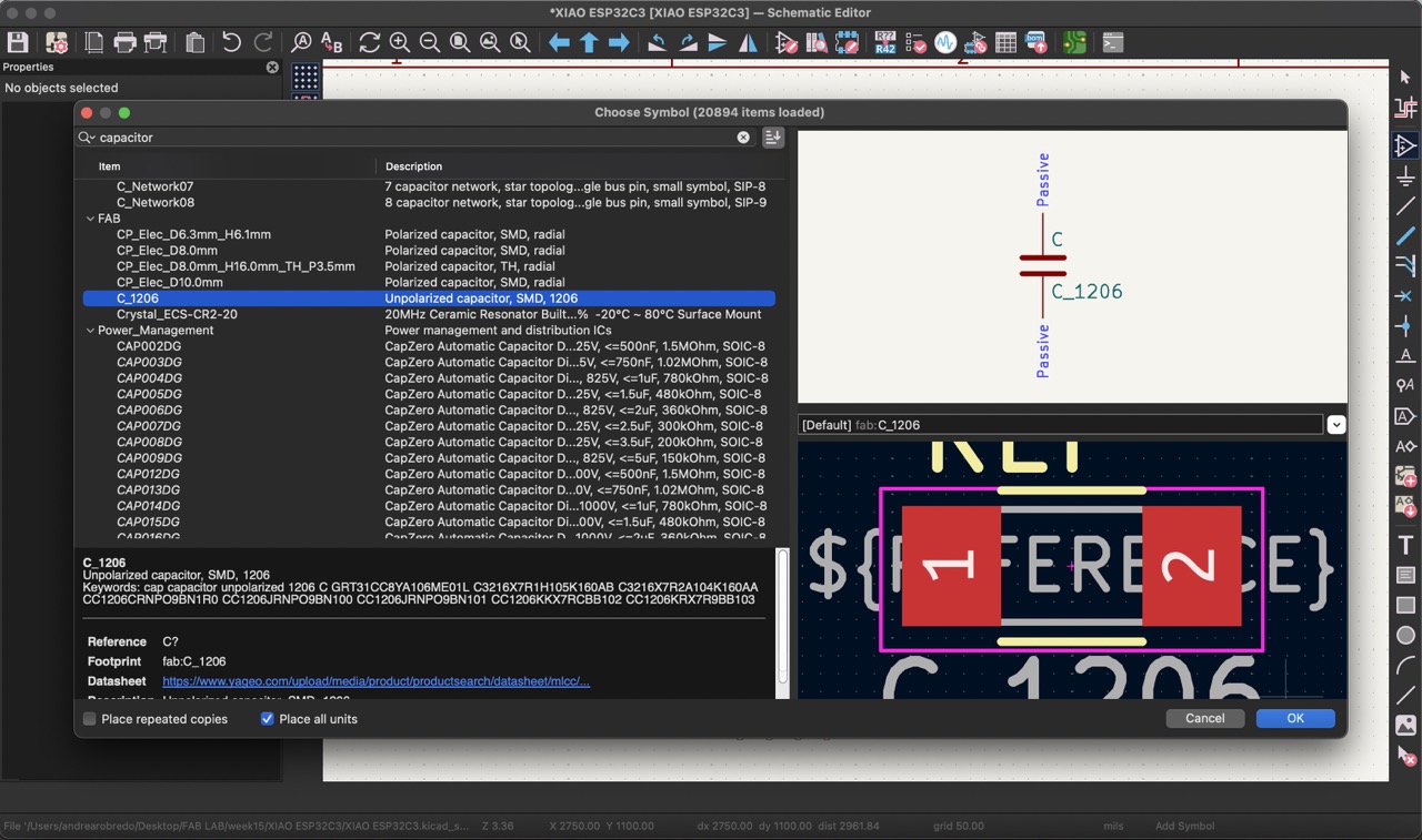
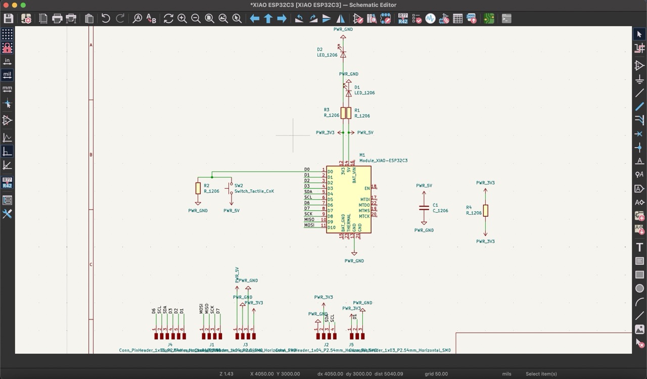
First, I added the XIAO ESP32-C3 module from the "FAB" library. I connected the voltage and ground pins and included a capacitor for electrical stability. Additionally, I decided to incorporate LEDs for each voltage to indicate when current is flowing.
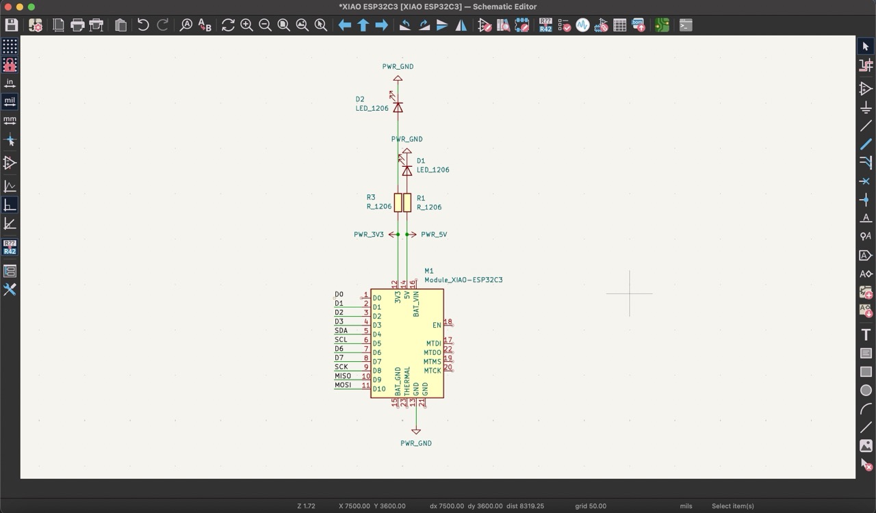
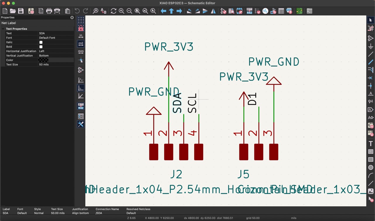
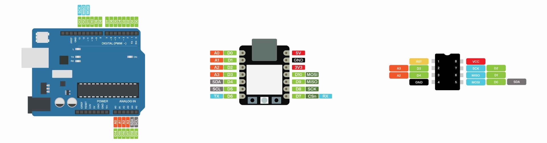
Then, using labels, I added all the pinouts, carefully referring to the pinout sheet of the XIAO ESP32-C3.
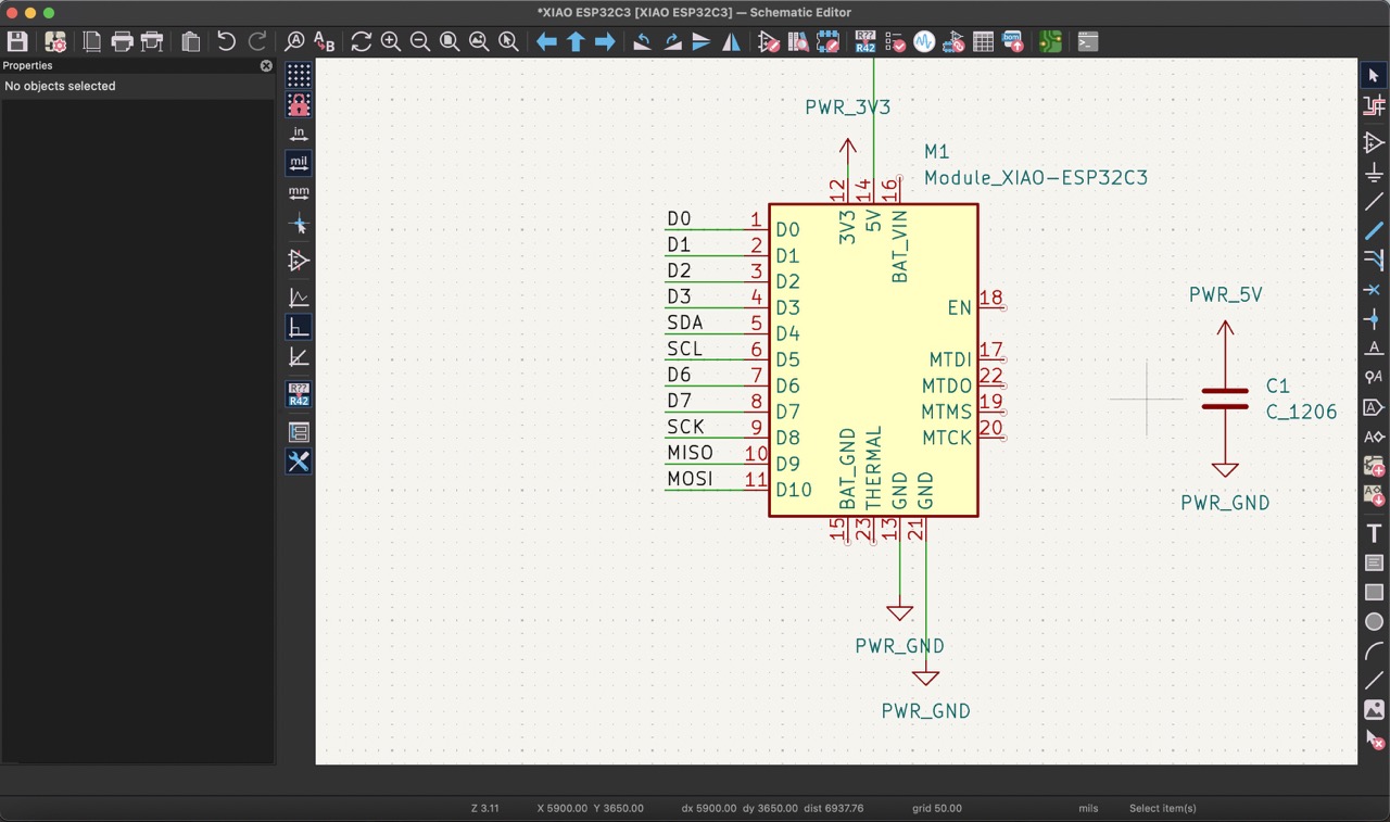
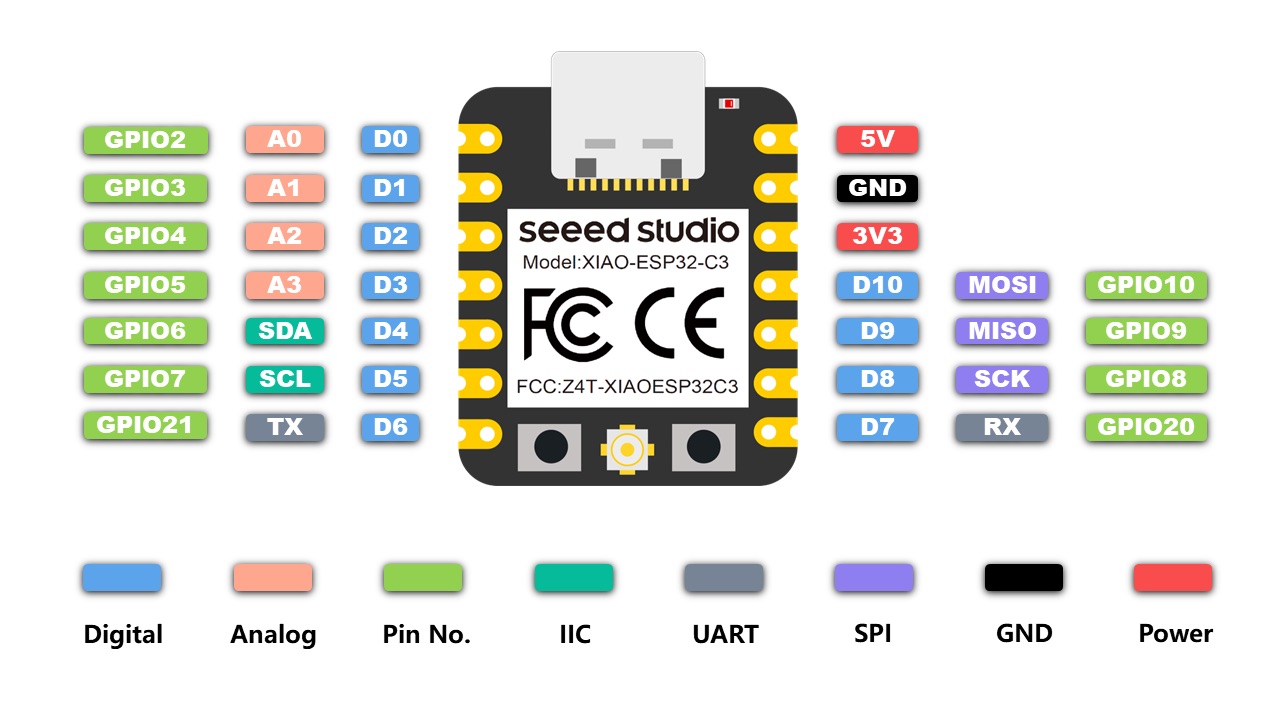
Finally, I included exposed pins for connections, considering those needed for the OLED display and three pins for reading analog signals from sensors. This arrangement will facilitate easier sensor connections and external devices.
This is the final schematic:
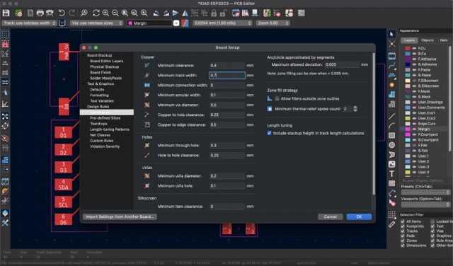
Moving to the PCB editor, I clicked on "Update PCB from schematic" under "Tools". In the "board setup" section, I adjusted the constraints, setting the minimum clearance to 0.4 mm and the minimum track width to 0.7 mm.
Organizing everything on the PCB proved to be a bit complex, but I successfully connected each pin to the corresponding track. Lastly, I added a frame to serve as the outline cut and set its thickness to 1 mm to align with the cutting tool diameter.
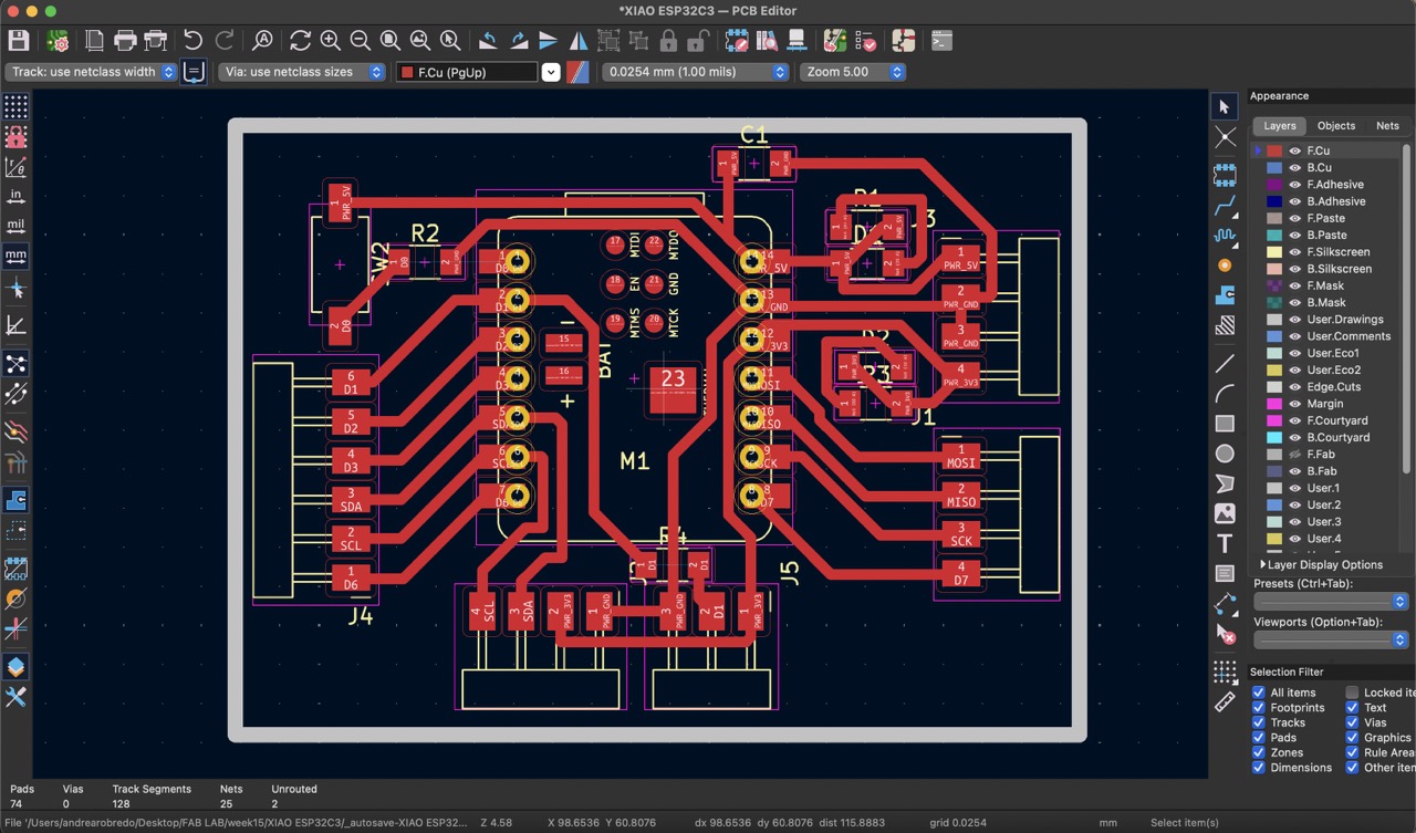
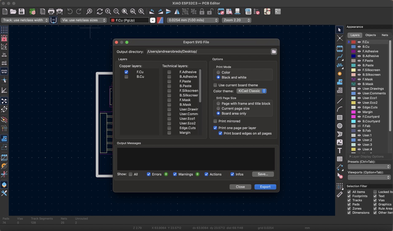
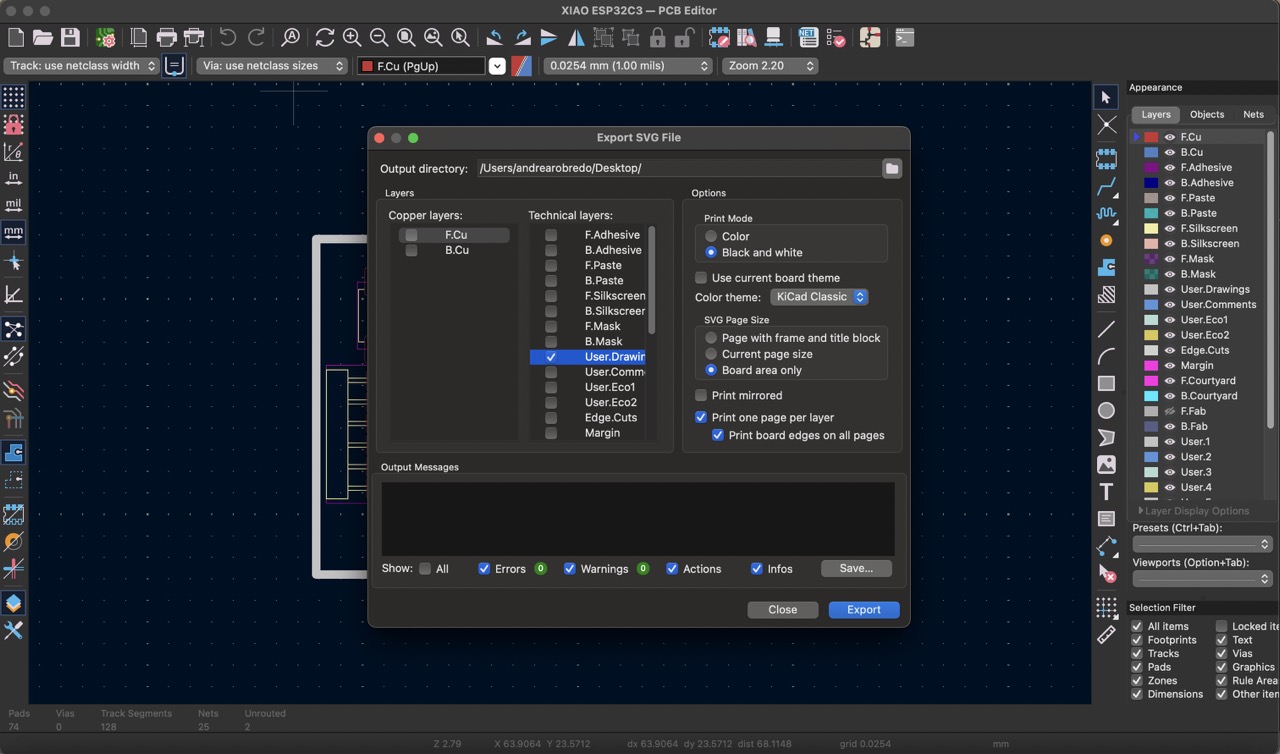
To finish I saved both the traces and the outline svg files.
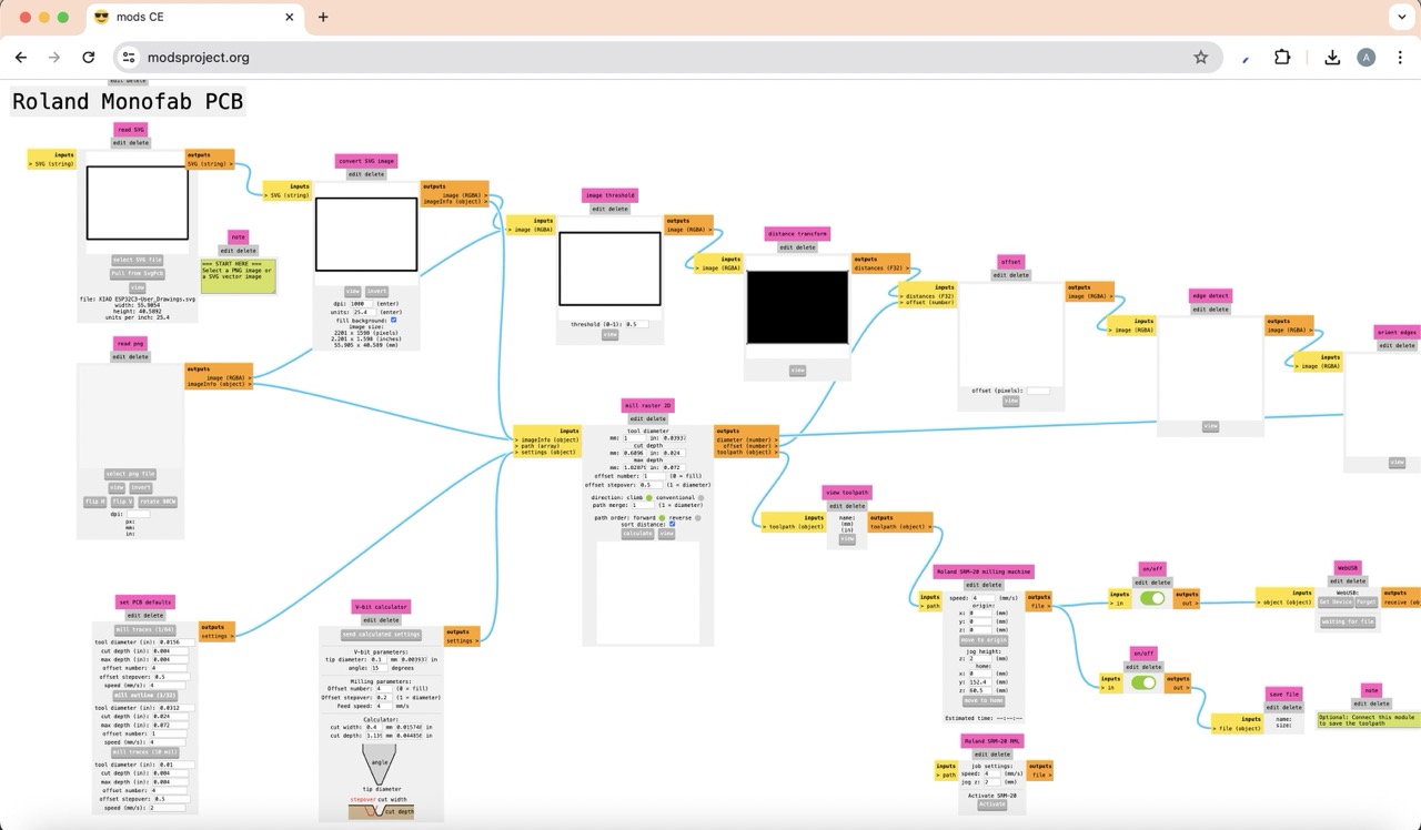
Mods
I first created the file to cut the traces of the PCB using the 'mods' platform. I uploaded the .svg file, made sure to invert it (since black represents the cutting area), and clicked on 'mill traces'. I then set the origin to 0, 0, 0.
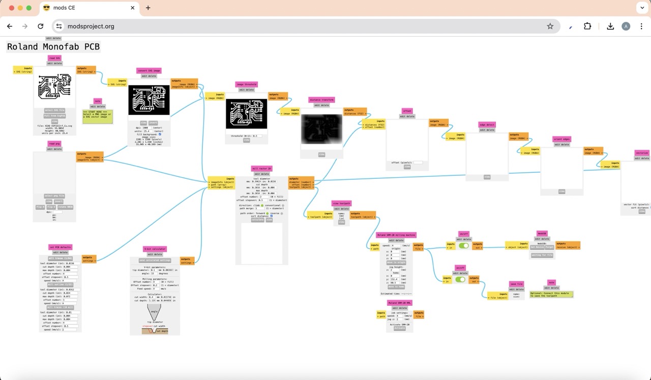
Next, I made the file to cut the outline by uploading the corresponding .svg file, clicking on 'mill outline', setting the origin to 0, 0, 0, and finally changing the tool diameter to 1mm.
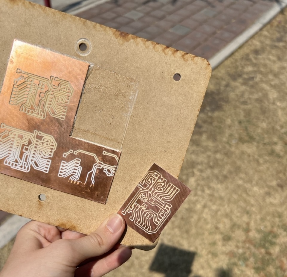
Cutting and soldering PCB board
After a few tries, I finally managed to cut my PCB correctly.
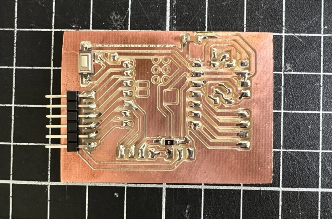
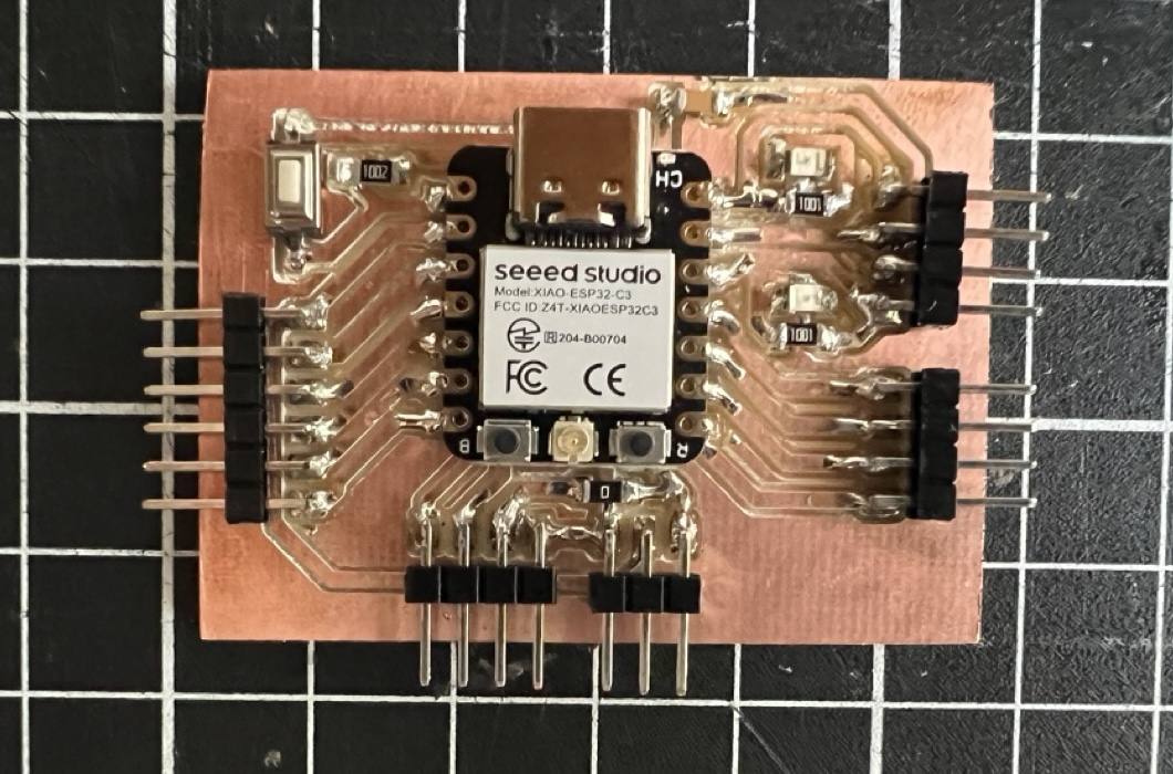
Next, I soldered each component until I had my final PCB board.
Experimenting with OLED display:
To start understanding how the OLED display worked I found this guide. It was very useful to begin experimenting with the code and observe how it was reflected in the display.
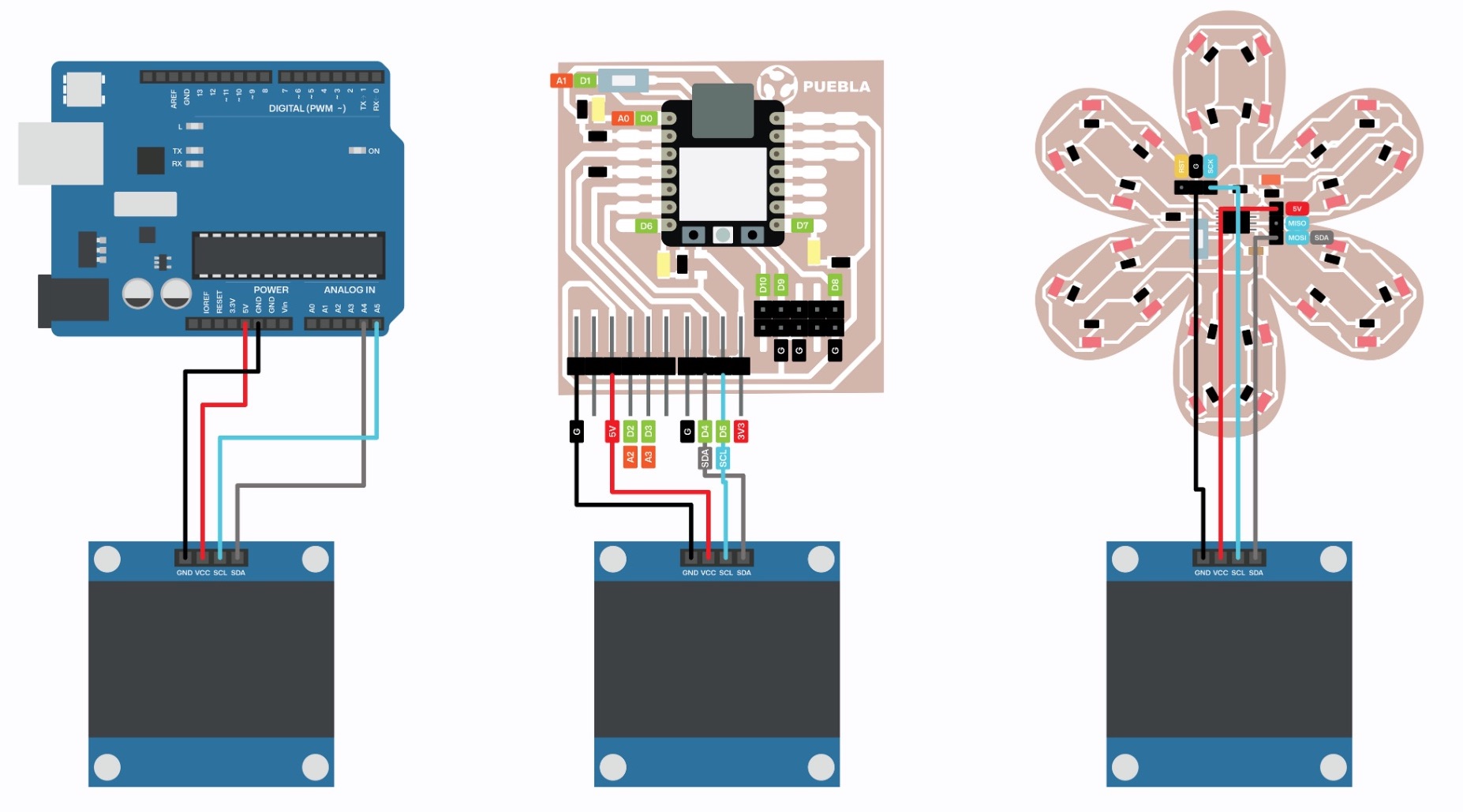
To begin, I created the following diagrams to show how to connect the OLED display to the Arduino Uno, to the Xiao and to the ATtiny flower design.
Setup
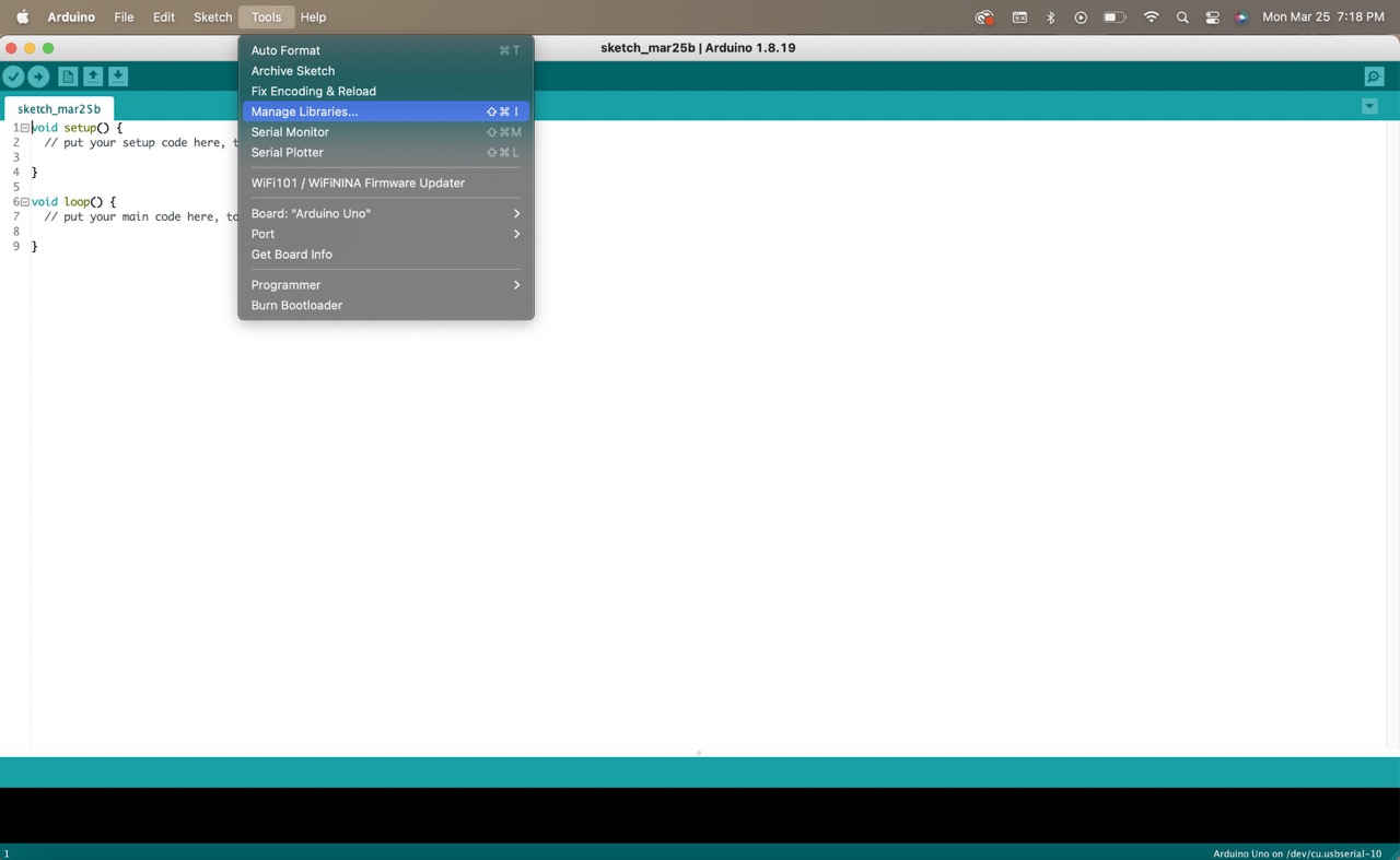
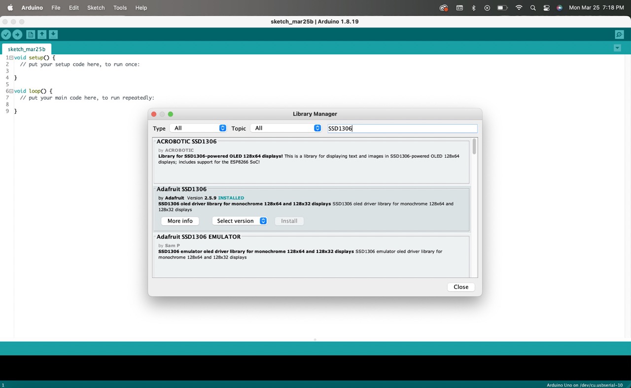
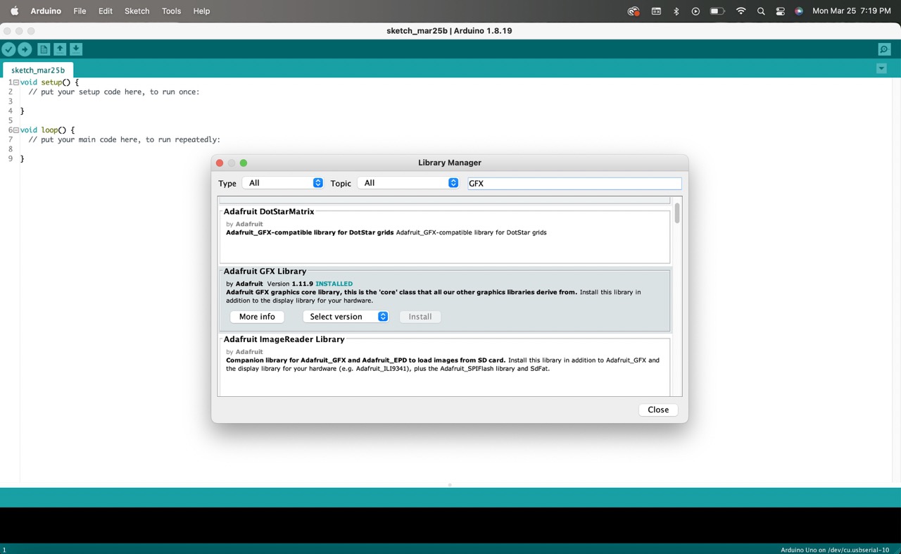
- To get started, open Arduino and navigate to 'Tools'. Click on 'Manage Libraries' and search for two libraries: 'Adafruit SSD1306' and 'Adafruit GFX', install them.
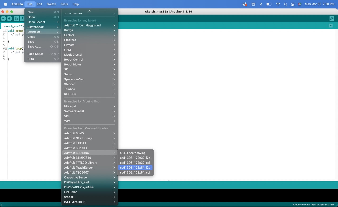
- Next, under examples, scroll down to 'Adafruit SSD1306' and select 'ssd1306_128x64_i2c'.
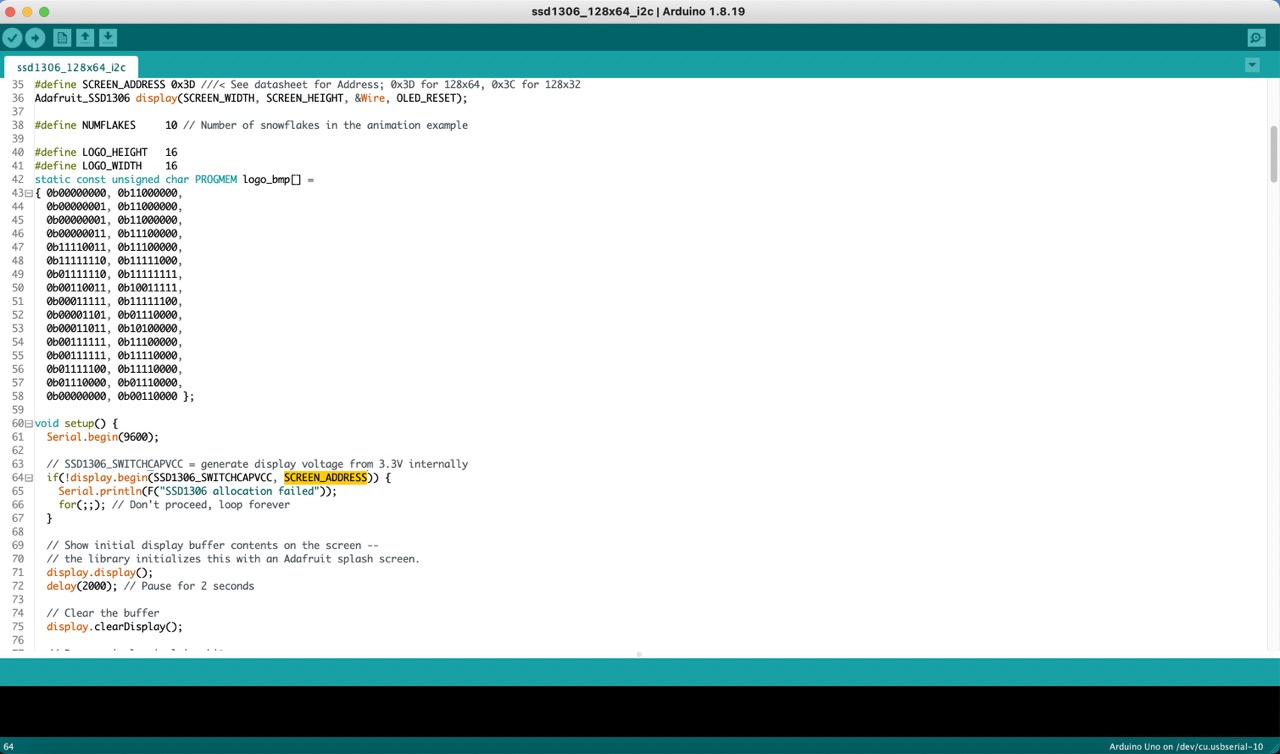
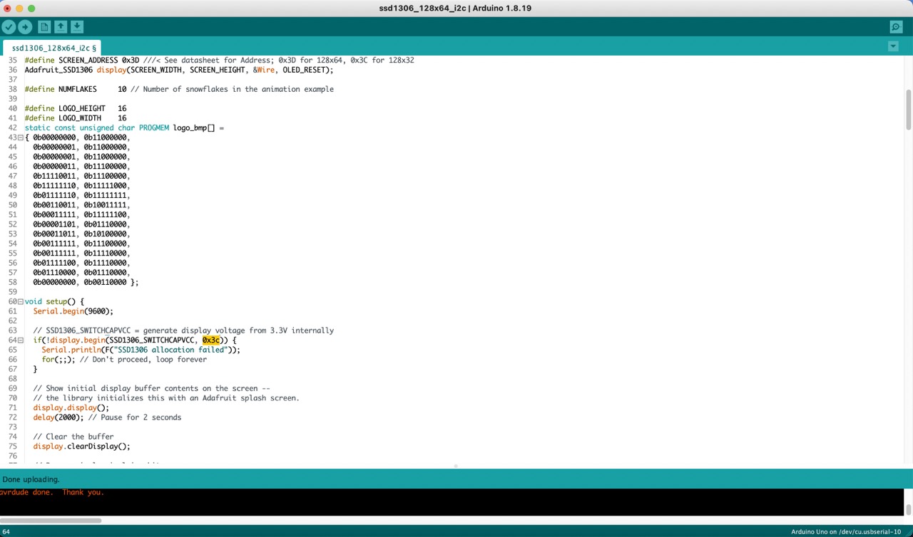
- Upload this code to verify that everything is working correctly, including the connections and the OLED screen.
- If it is not working, change the ‘SCREEN_ADDRESS’, in my case to ‘0x3C’.
Shapes
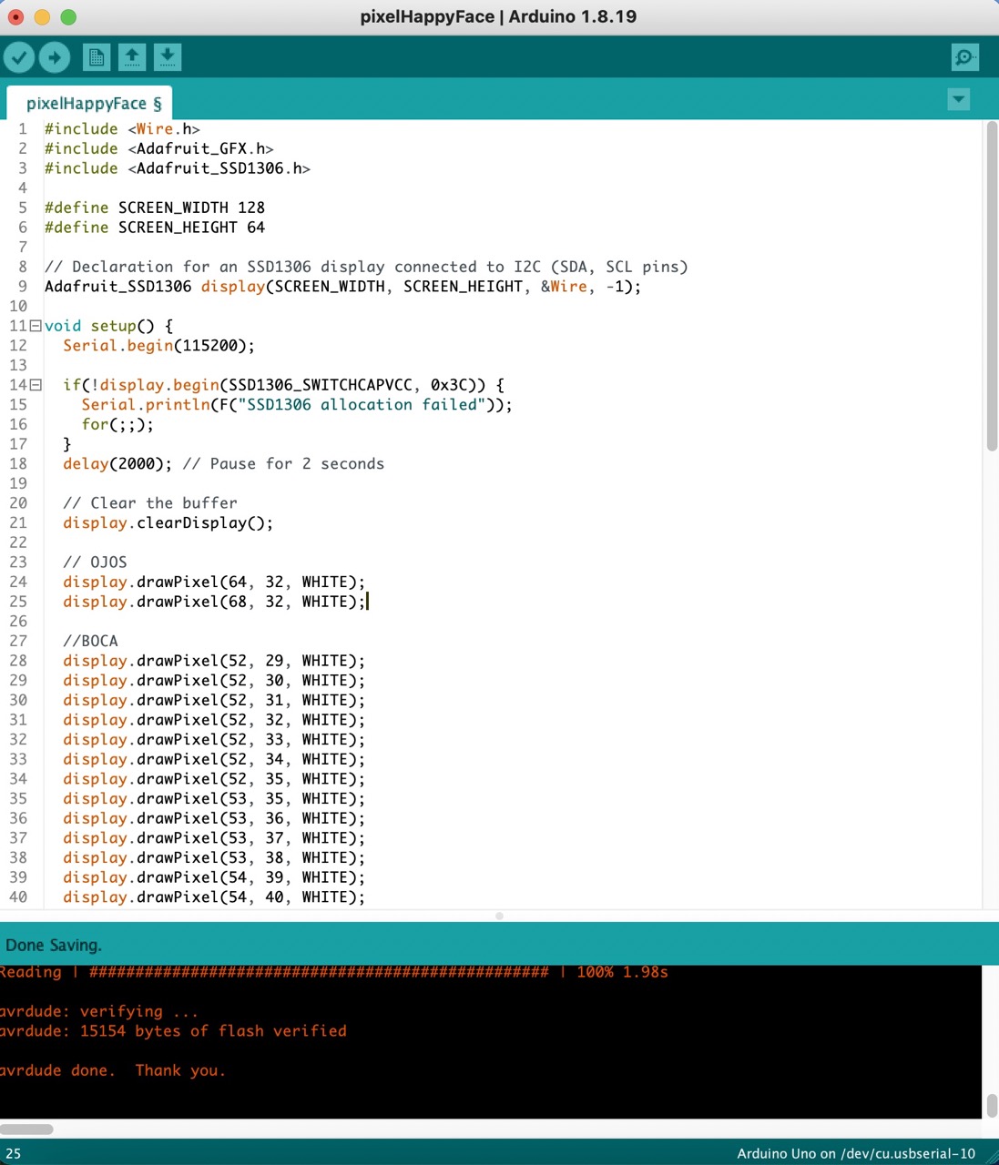
Pixels
To begin, I started drawing pixels to form a happy face. While it may seem simple, it was actually more challenging than I anticipated.
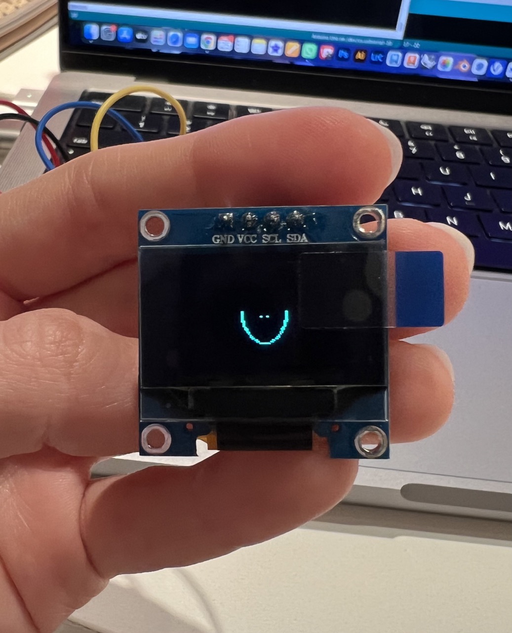
Line

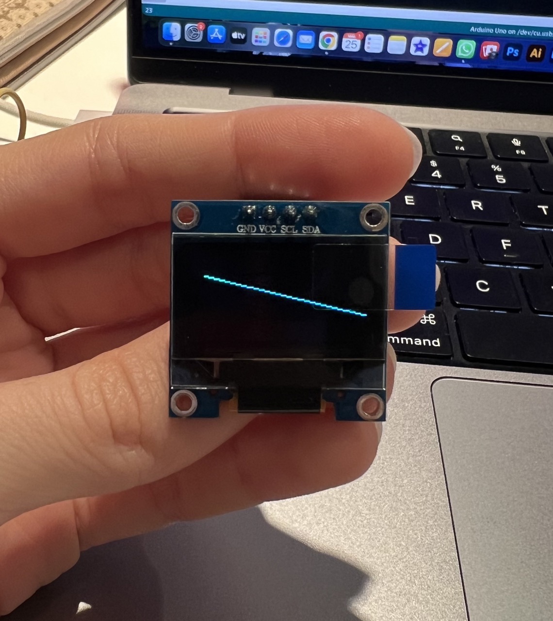
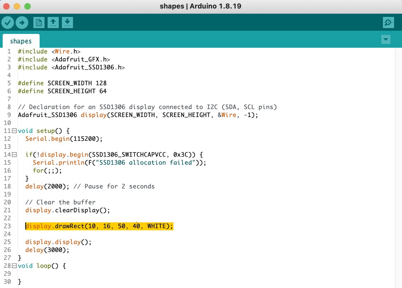
Rectangle
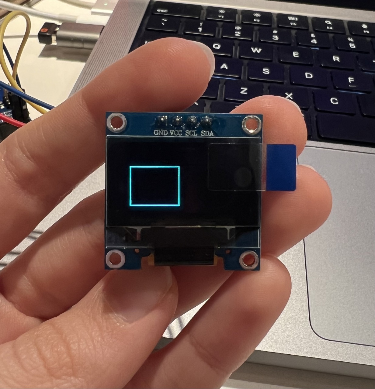
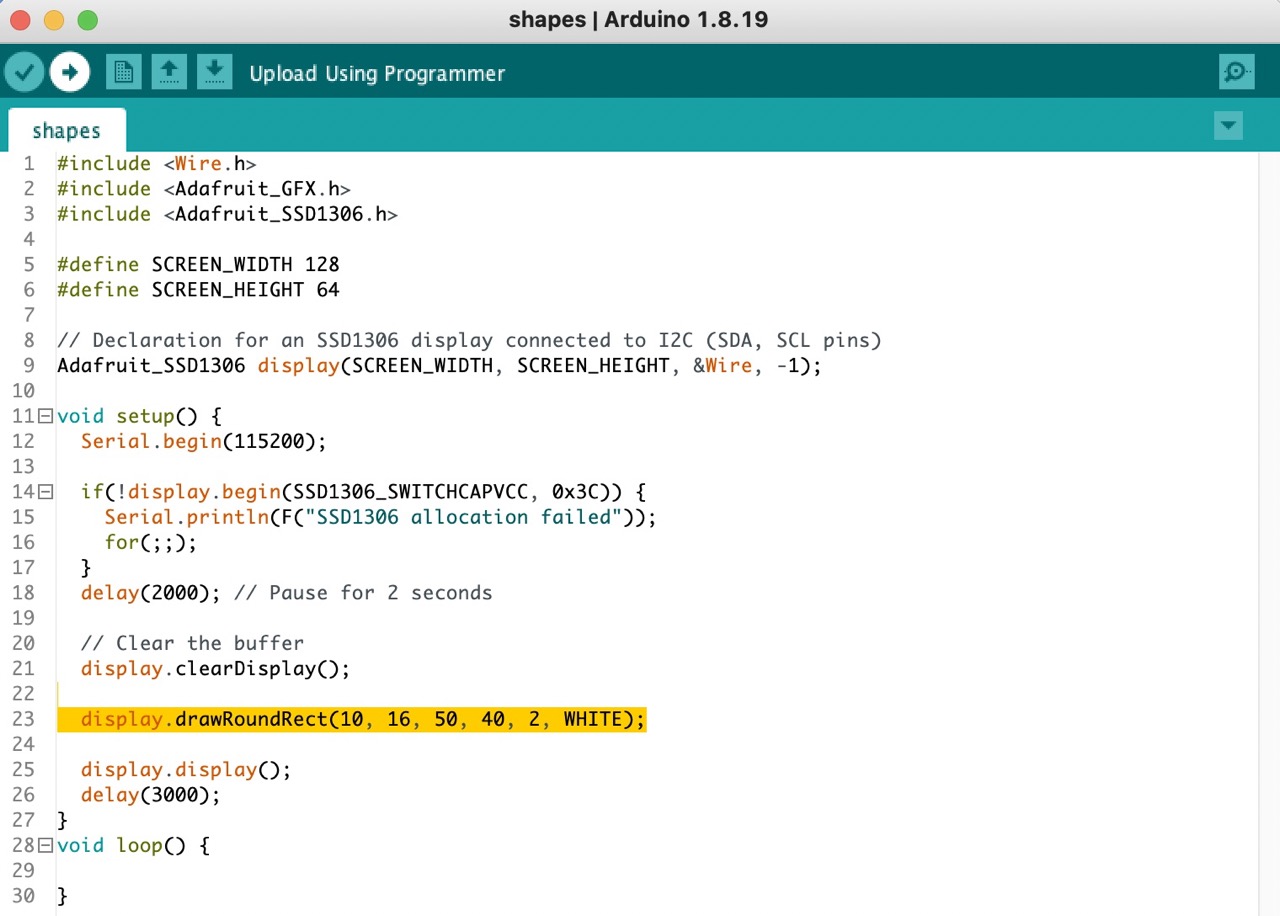
Rounded rectangle
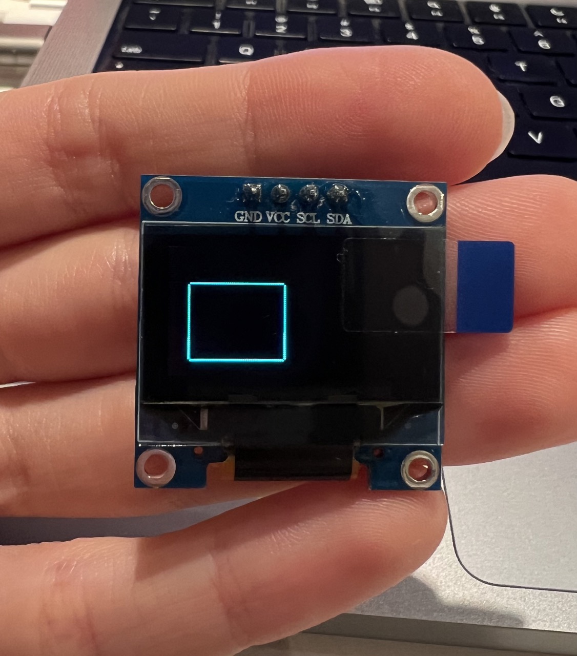
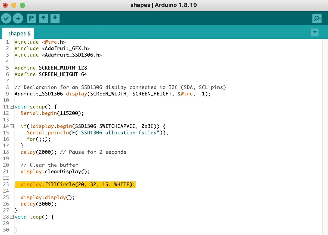
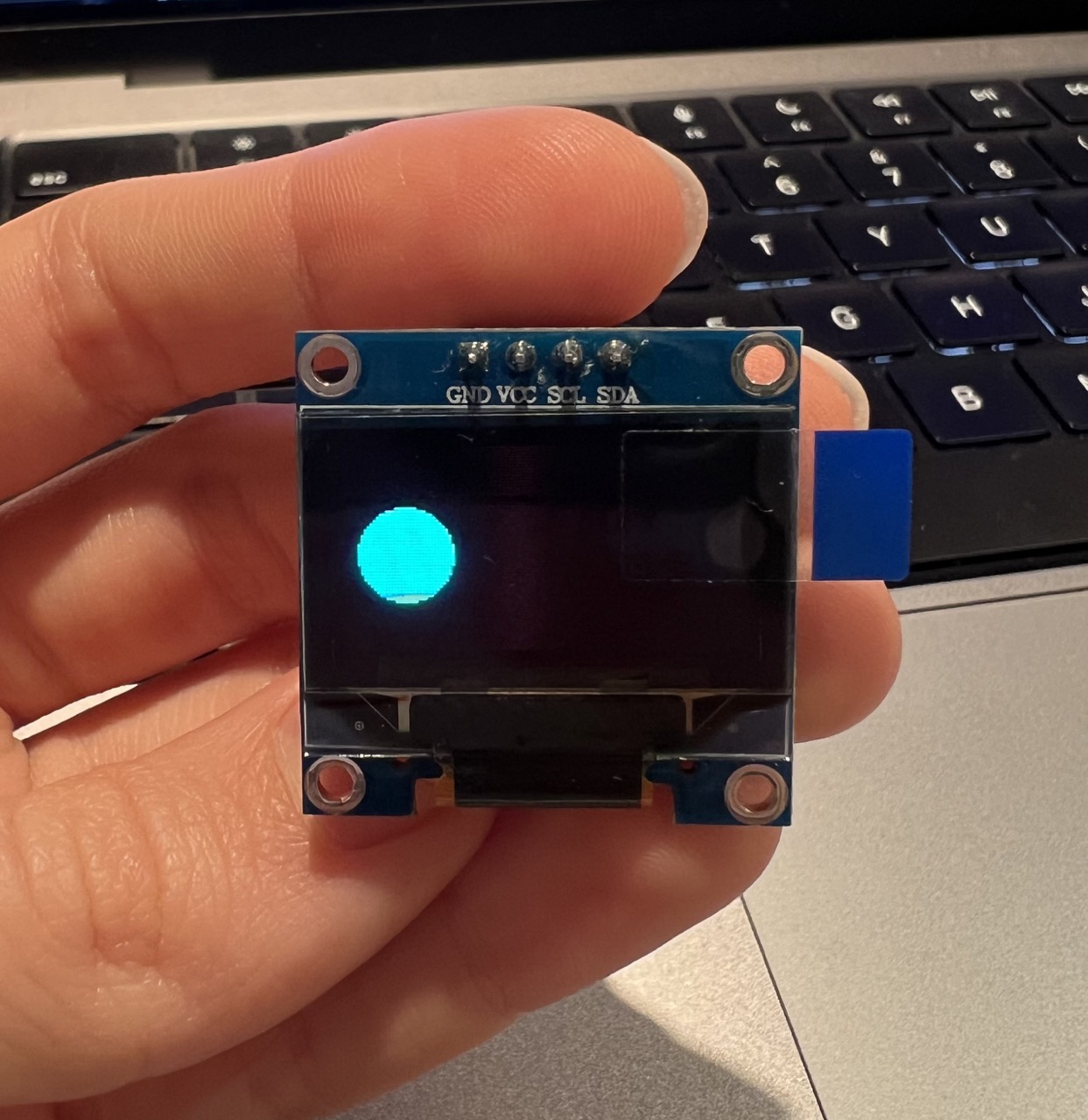
Filled circle
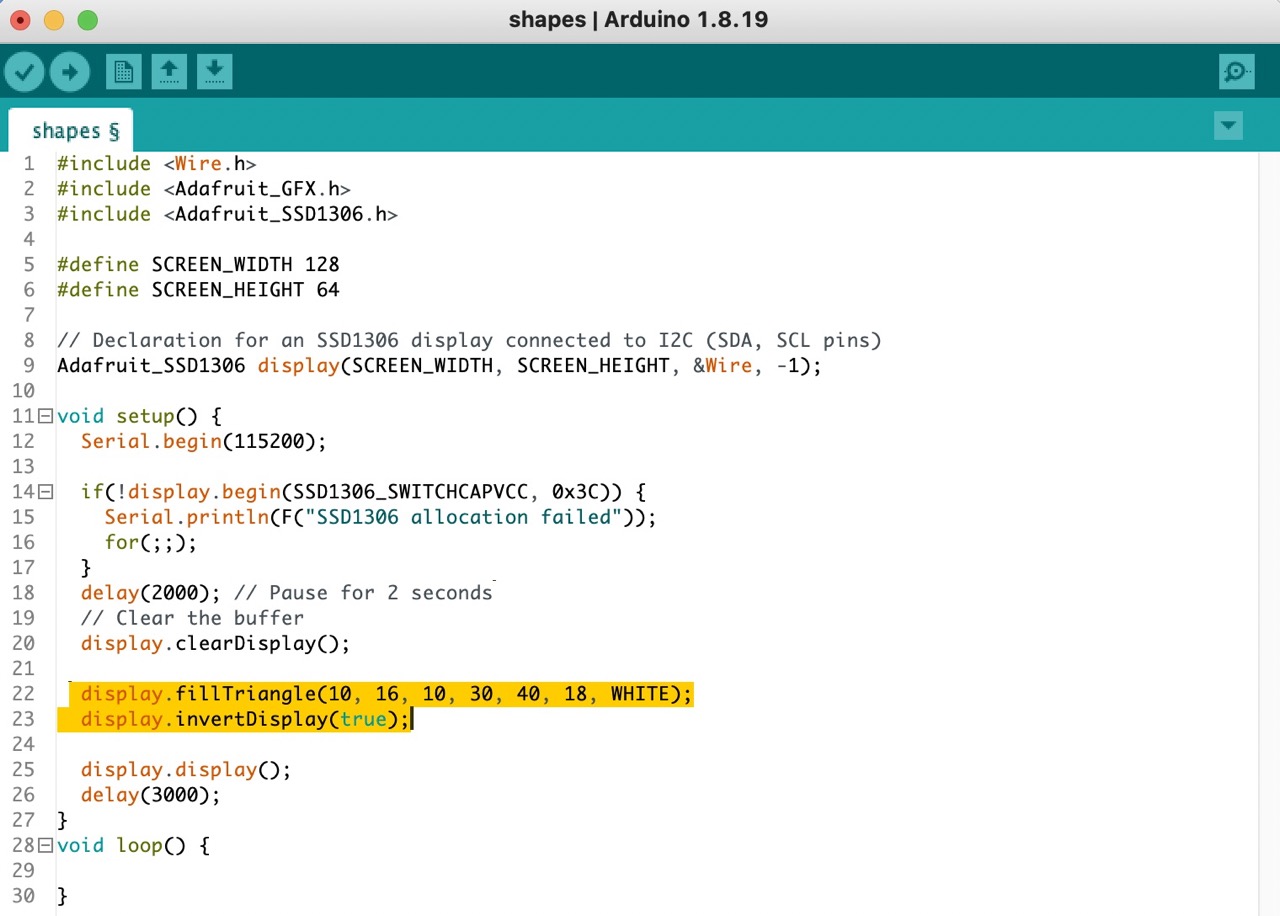
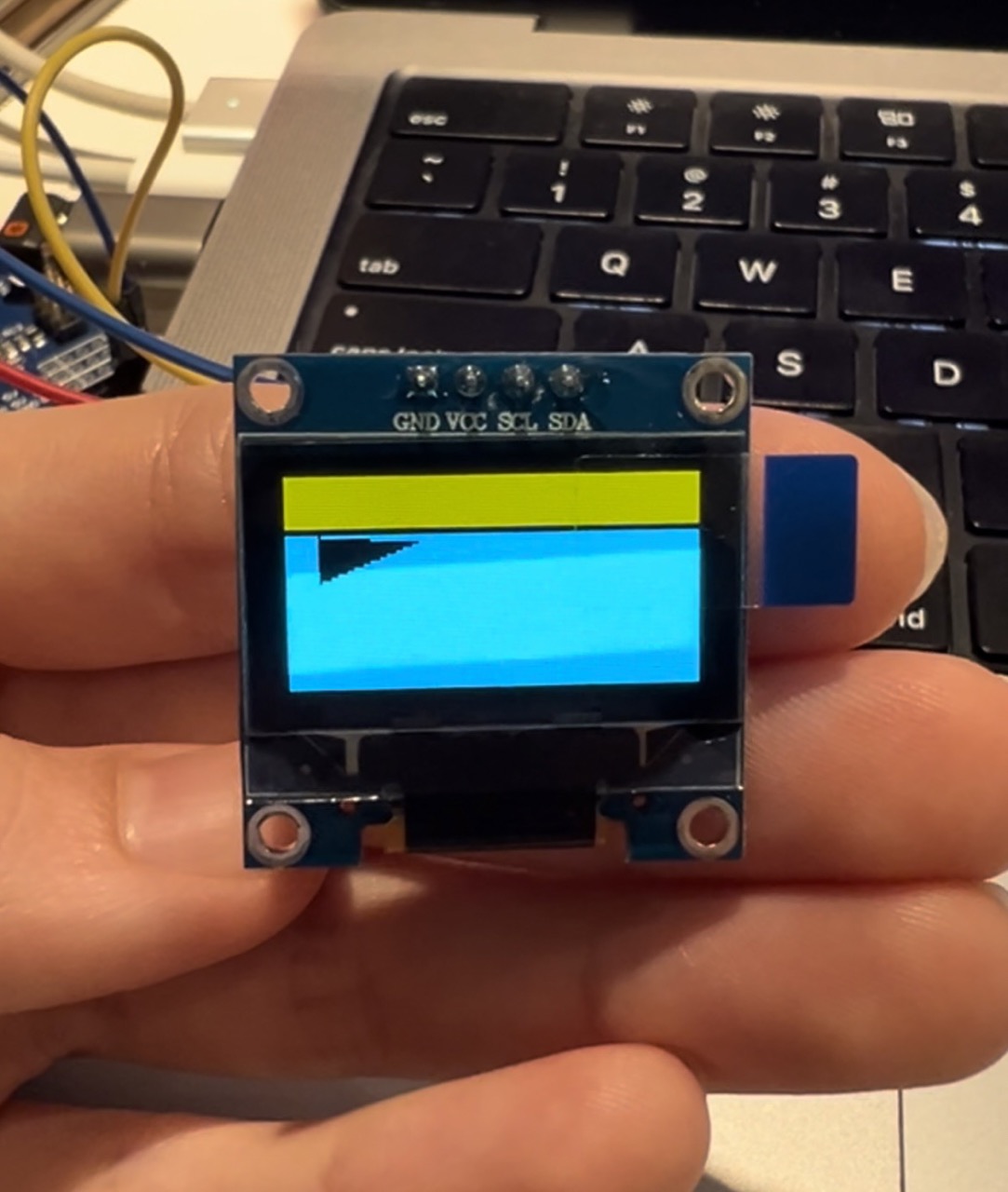
Triangle - inverted fill
In the following table you will find the codes corresponding to different shapes.
Shape |
Code |
|---|---|
| Pixel | display.drawPixel(x, y, color) |
| Line | display.drawLine(x1, y1, x2, y2, color) |
| Rectangle | display.drawRect(x, y, width, height, color) |
| Filled rectangle | display.fillRect(x, y, width, height, color) |
| Rounded rectangle | display.drawRoundRect(x, y, width, height, round, color) |
| Filled rounded rectangle | display.fillRoundRect(x, y, width, height, round, color) |
| Circle | display.drawCircle(x, y, radius, color) |
| Filled circle | display.fillCircle(x, y, radius, color) |
| Triangle | display.drawTriangle(x1, y1, x2, y2, x3, y3, color) |
| Filled triangle | display.fillTriangle(x1, y1, x2, y2, x3, y3, color) |
| Invert | display.invertDisplay(true) |
Text
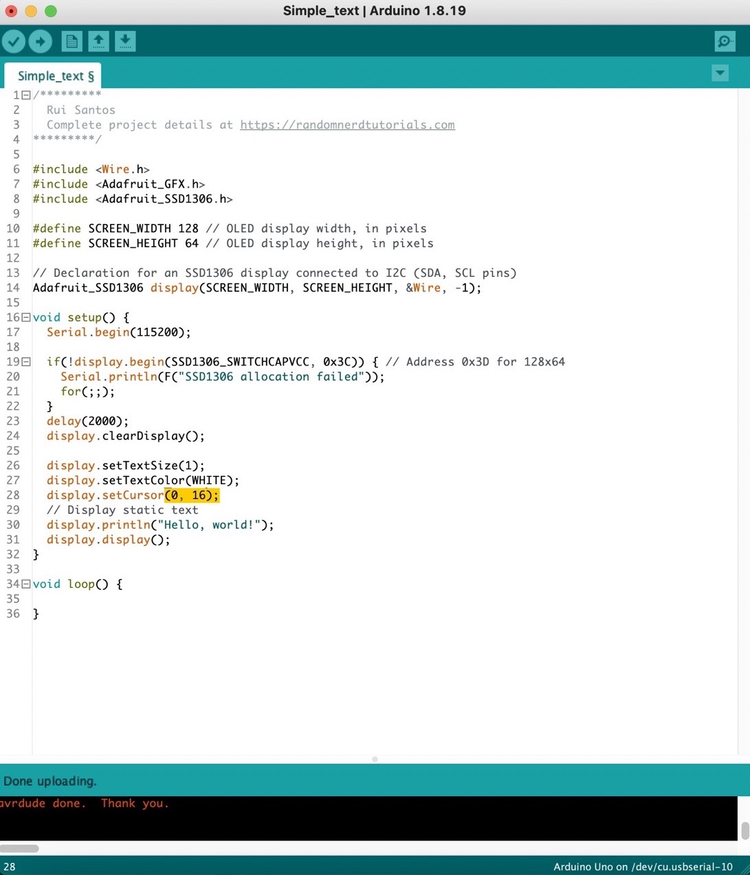
I began with a basic "Hello World!" example I found on the online guide I previously linked. Since this was a very basic example, I wanted to edit the code further to learn more.
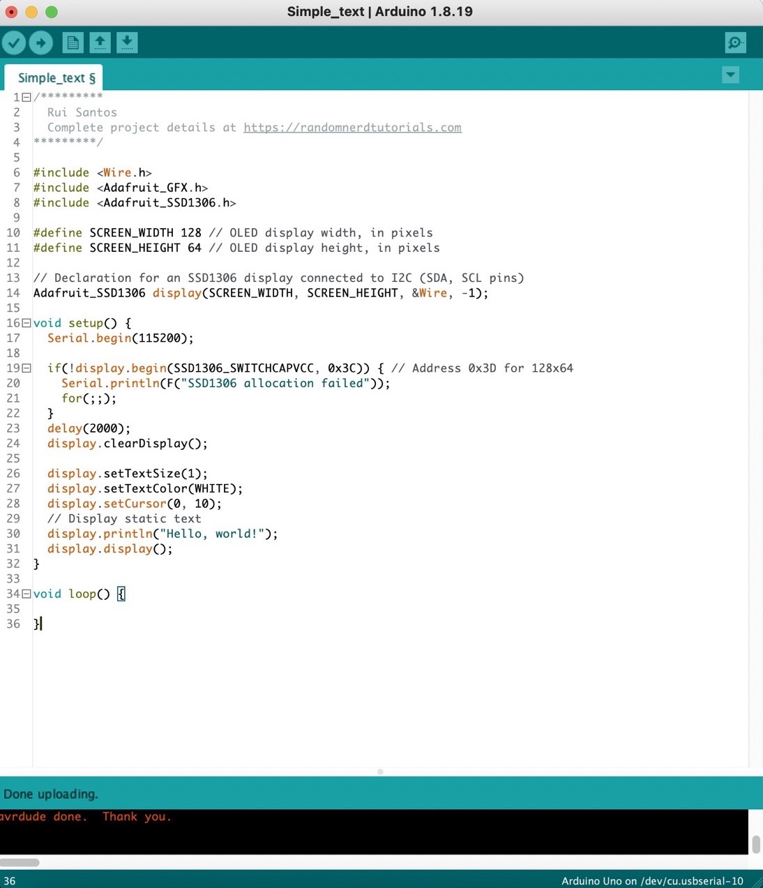
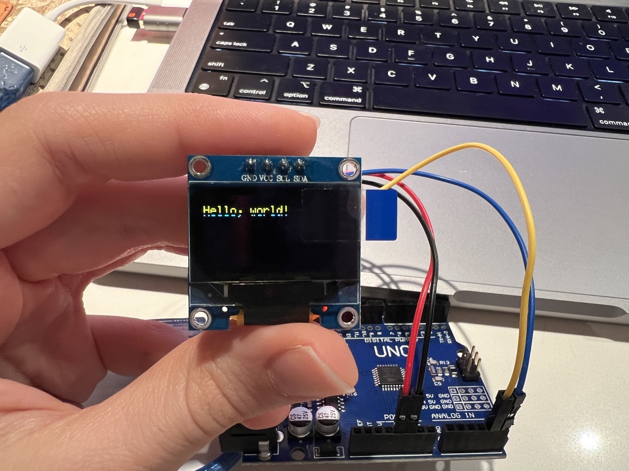
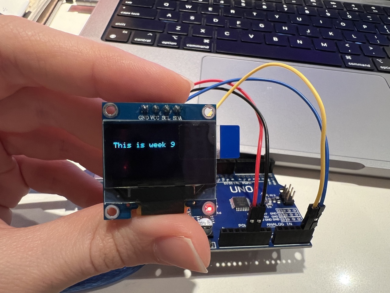
Initially, I decided to adjust the text's position on the 'y' coordinate since my screen displays both yellow and blue colors. I wanted the text to appear only in blue. To achieve this, I made a simple adjustment to the ‘display.setCursor’ on the ‘y’ coordinate changing it from 10 to 16.
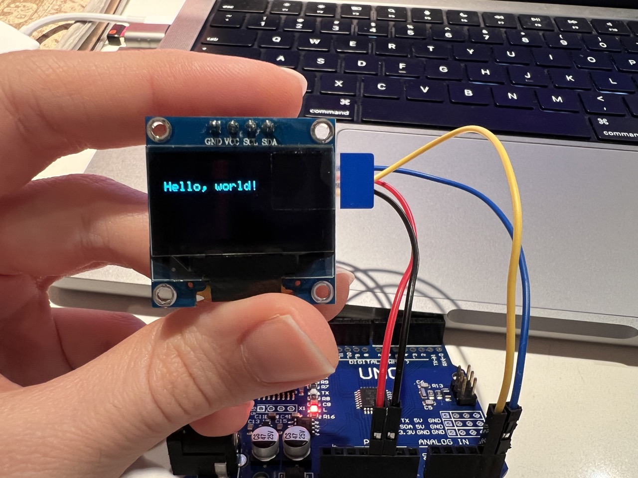
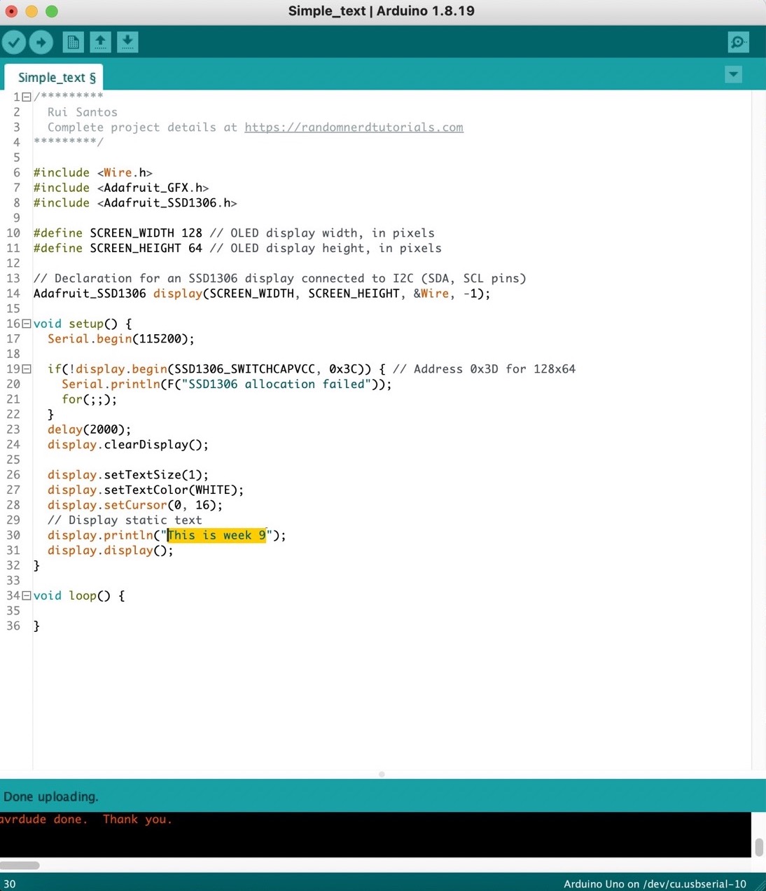
Next, I changed the text in the ‘display.println’ from "Hello World!" to "This is week 9".
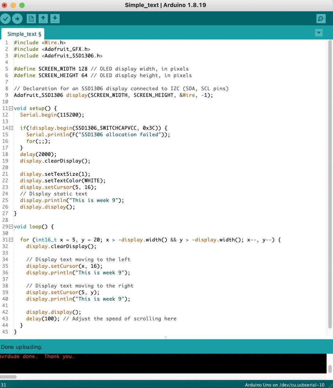
Afterwards, I attempted to make the text move left and right. Although my first attempt didn't produce the desired effect, it still looked cool.
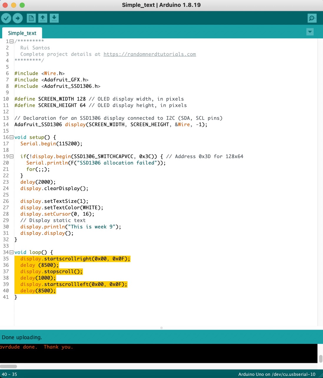
I realized I was making things more complicated than necessary. Eventually, I discovered a method to smoothly scroll the text from left to right, achieving exactly what I wanted.
Images
1:
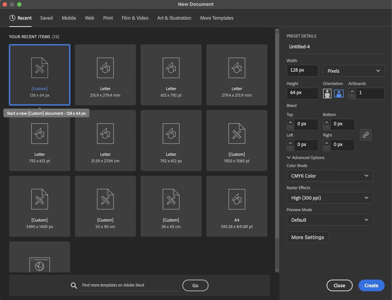
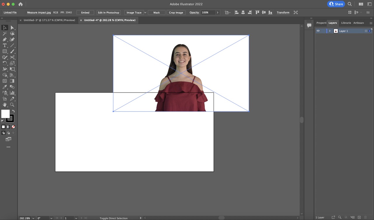
To start, I opened a new Adobe Illustrator document with dimensions 128 px by 64 px to match the OLED screen size.
2:
I then imported the desired photo by dragging and dropping it into the document.
3:
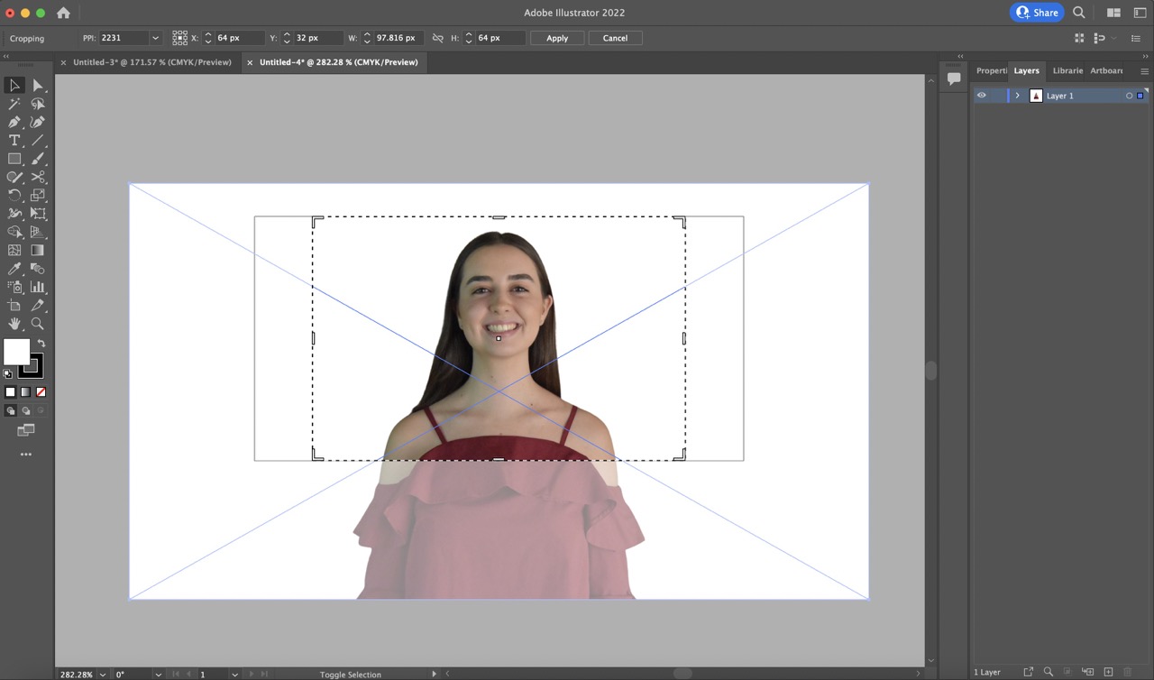
I cropped the photo for better detail on the small display.
4:
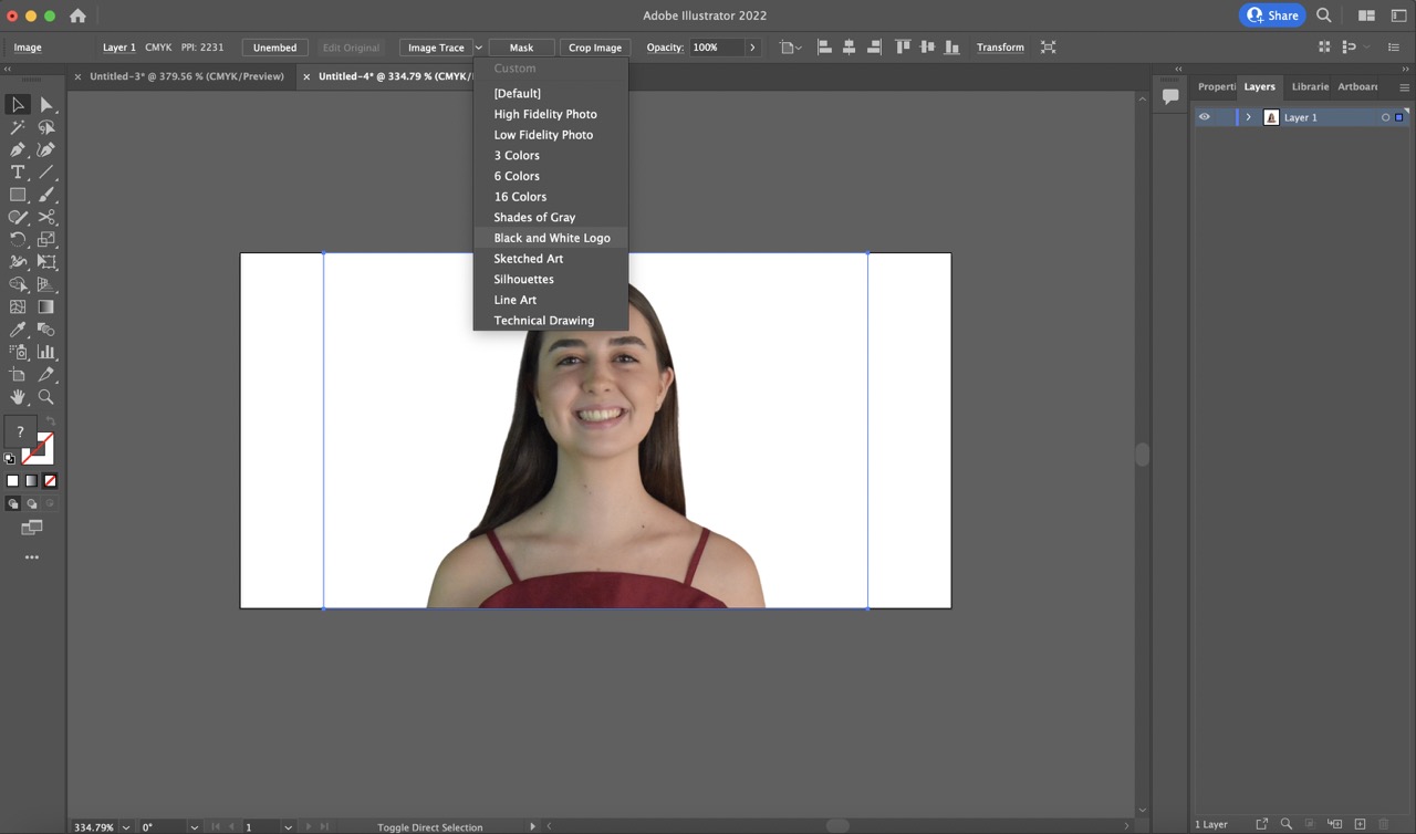
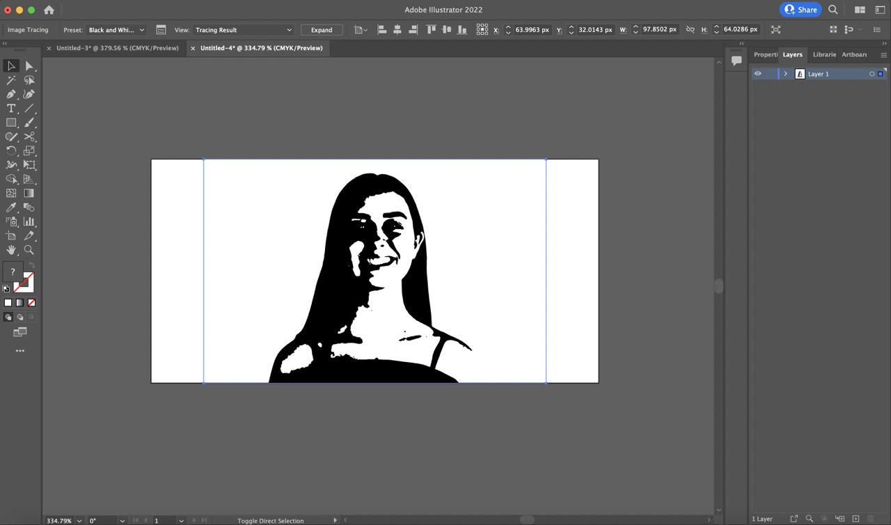
Then, while selecting the image, I applied the 'Black and White logo' option from the 'Mask' menu to create a black and white version for use in C code.
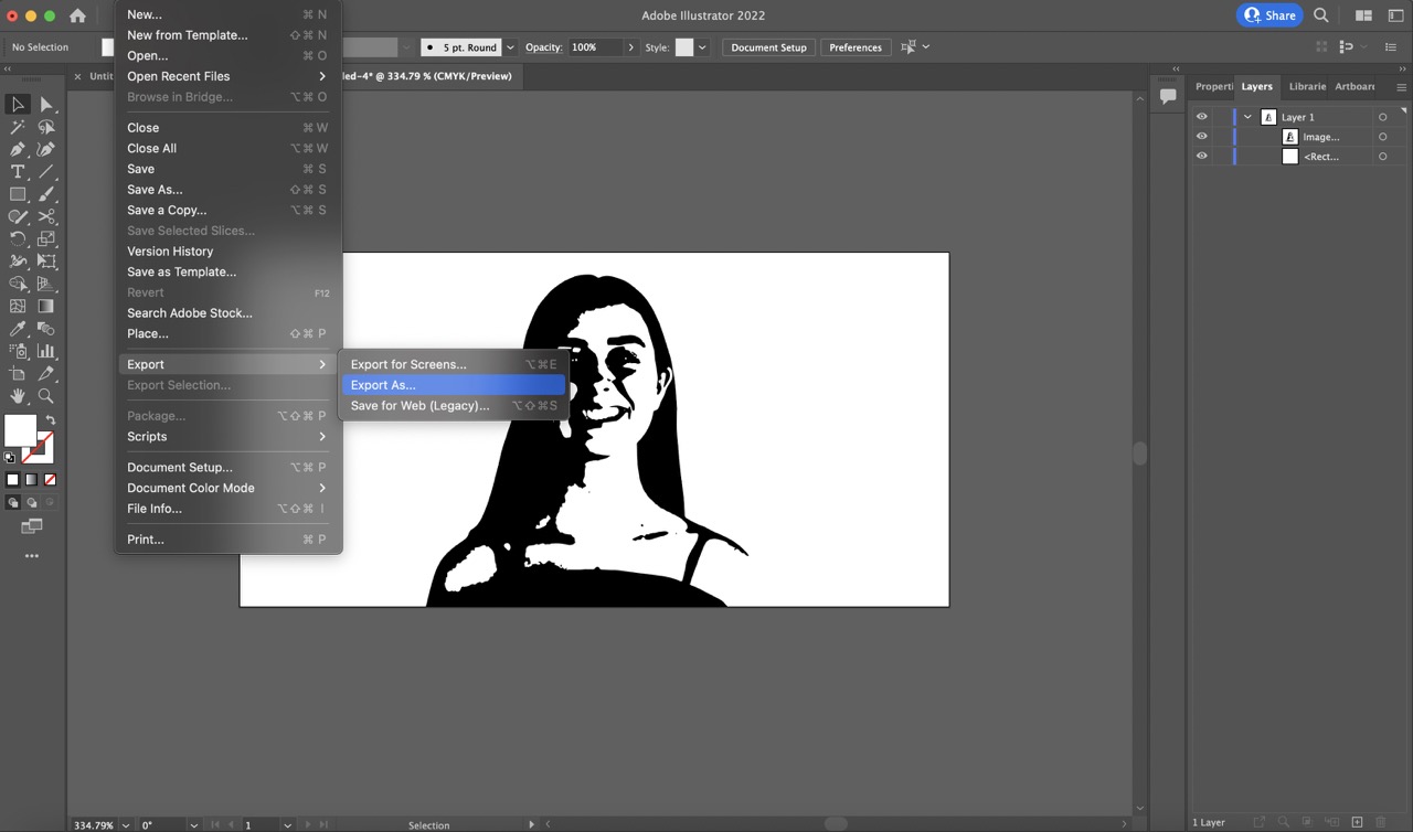
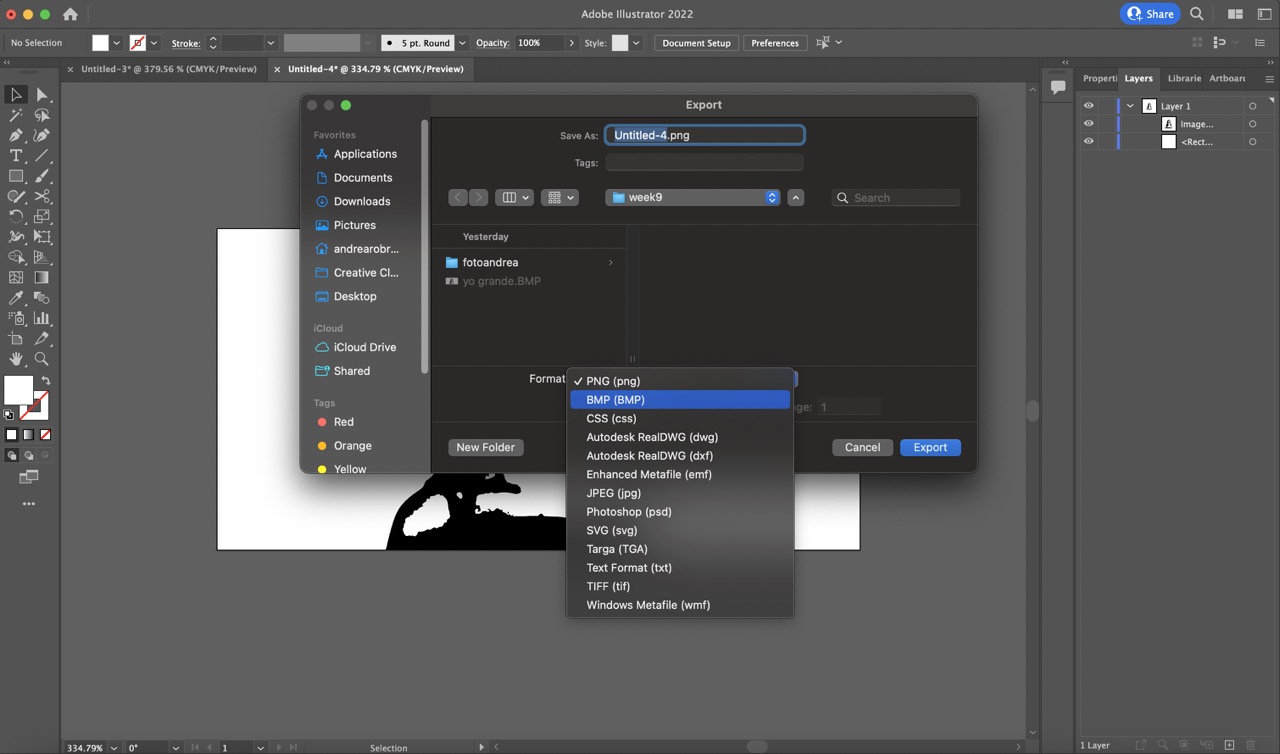
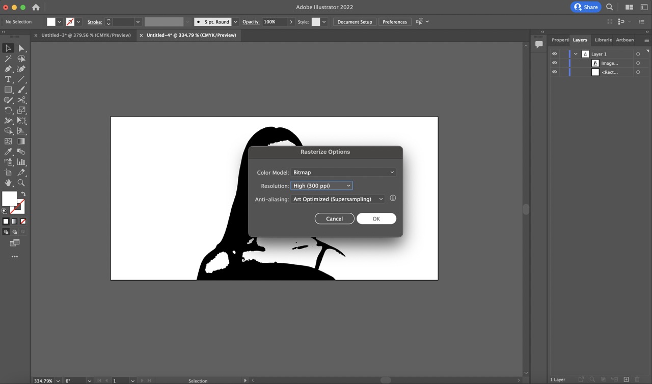
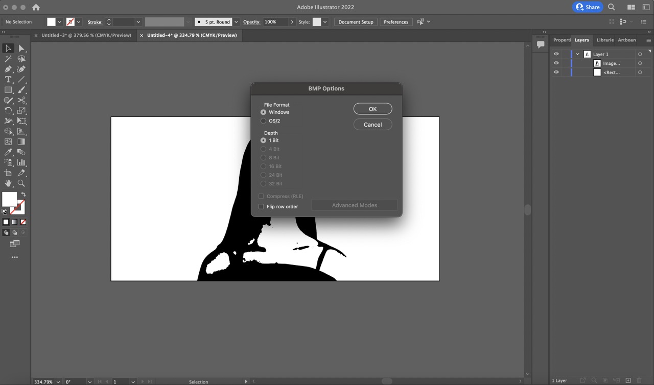
5:
Exported the image as a Bitmap (BMP) file.
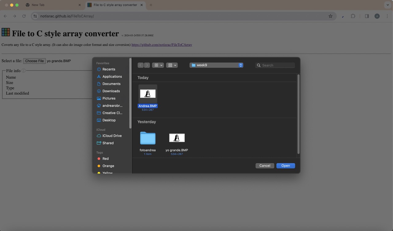
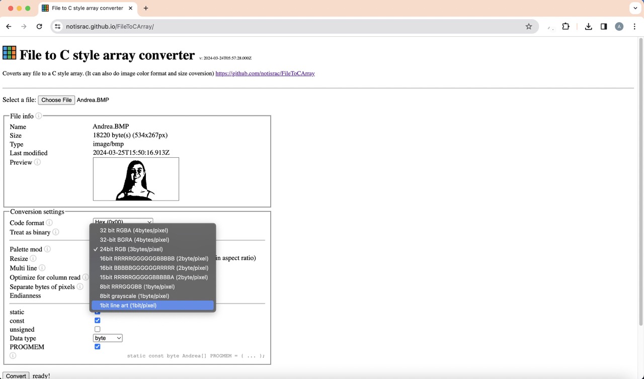
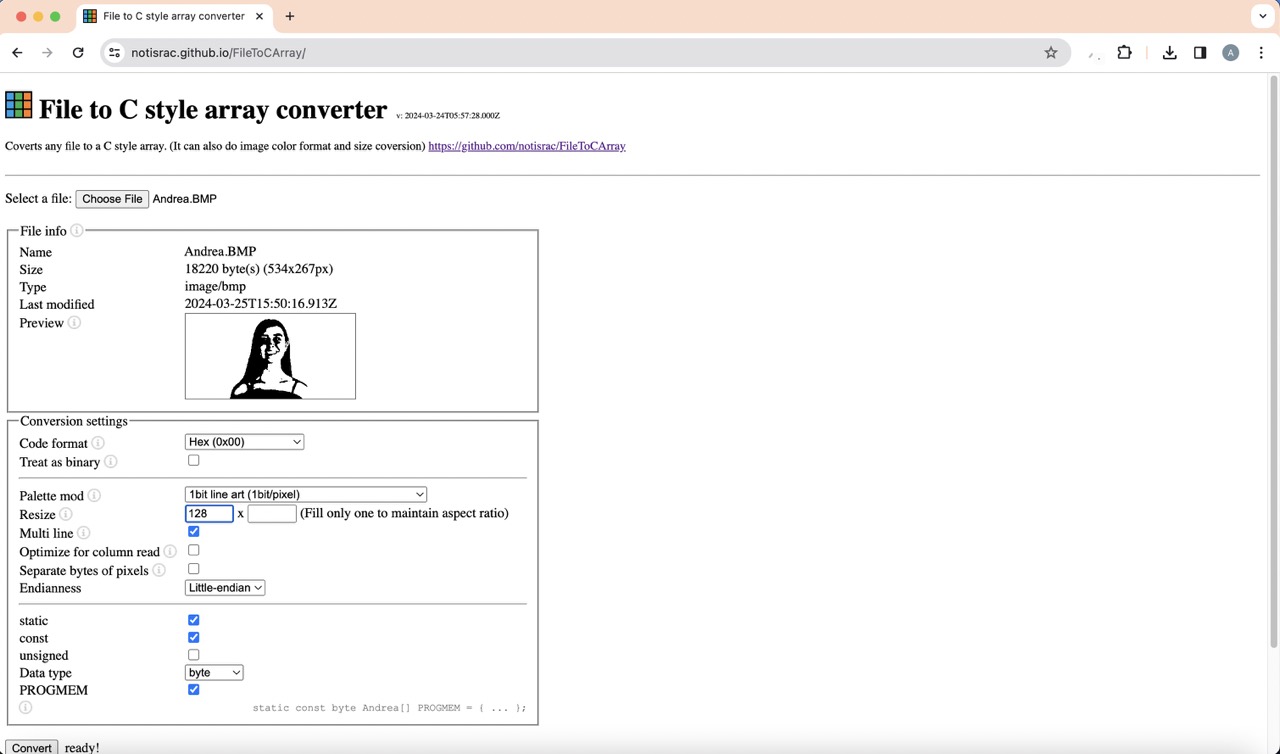
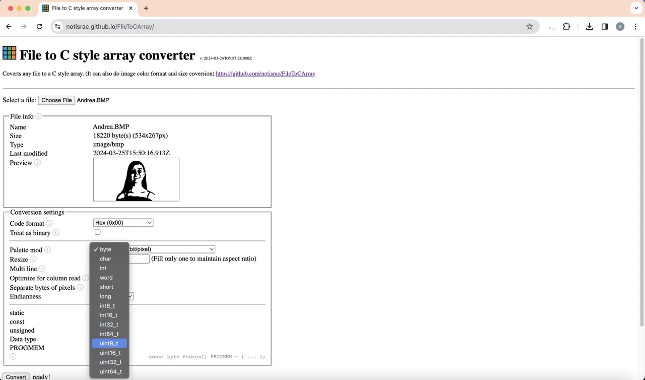
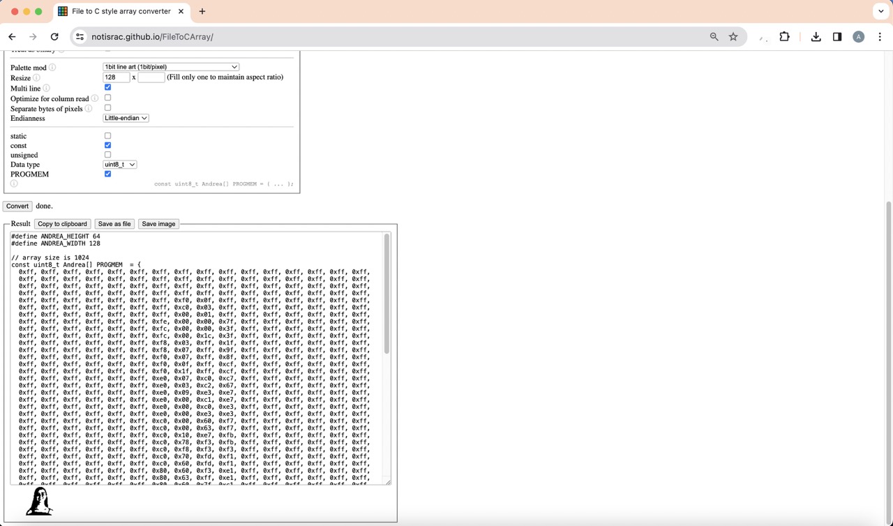
6:
Used a website to convert the BMP file to C code. I began by importing the Bitmap, chose 'Hex (0x00)' code format, '1 bit line art' Palette Mod, resized it to 128 px to match the screen size. Selected Little-endian, enabled the const option, and changed the 'Data type' to 'uint8_t'.

7:
Finally I clicked on the 'Convert' button to obtain the C code.
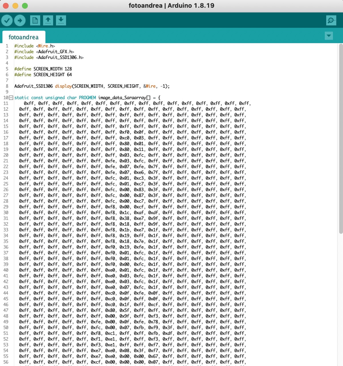
8:
I then copied the C code into the arduino code and uploaded it.
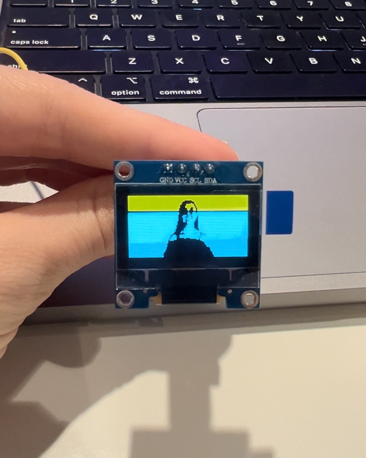
9:
This was the final result.