7. computer-controlled machining
I really enjoyed this week, I love the process of designing something and making it real. In addition to the hands-on work, we also participated in a safety course to identify and mitigate potential risks associated with operating CNC machines. Furthermore, we gained valuable insights into the various parameters essential for precise and efficient cutting with the CNC. For more detailed information on our safety training and CNC parameters, please refer to our group page.
Designing with Rhino
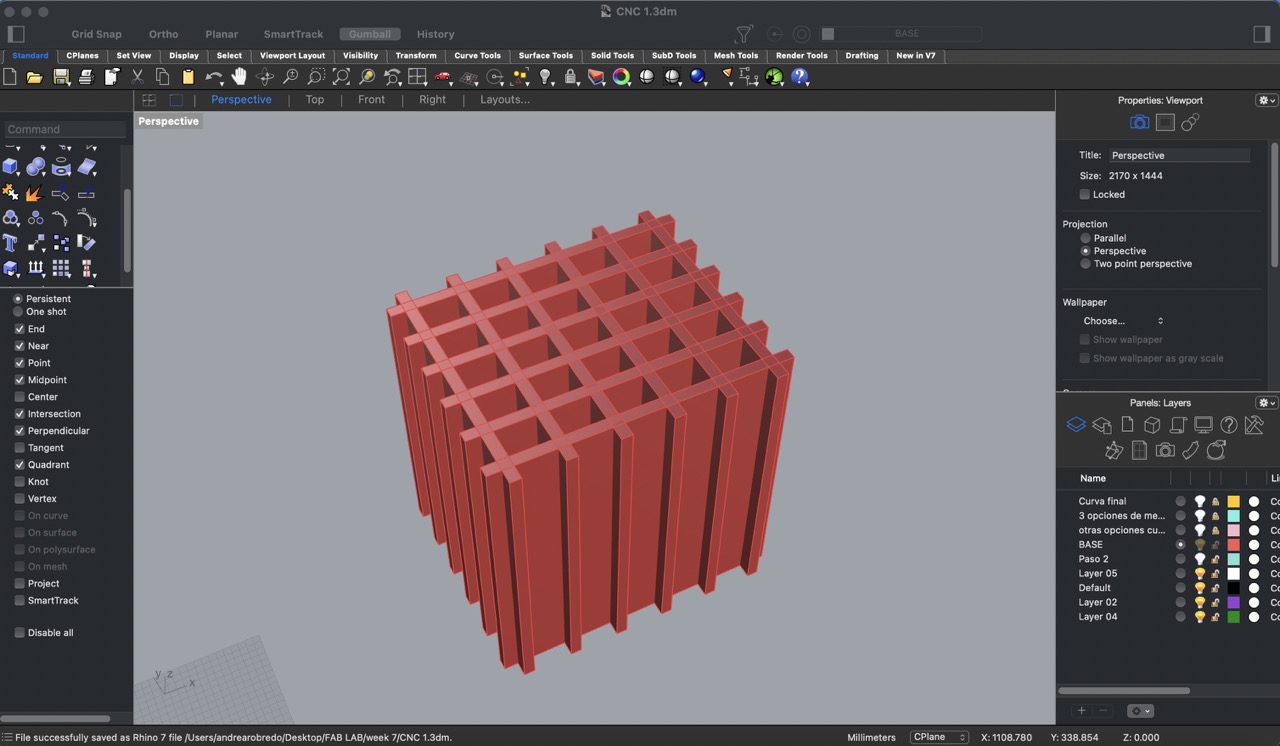
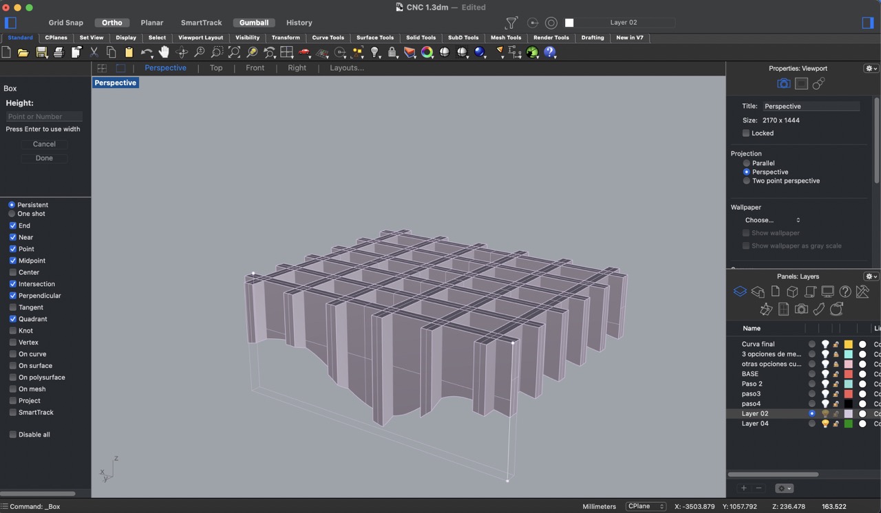
1:
To begin, I created a grid of rectangular prisms, keeping in mind the material thickness of 15 mm.
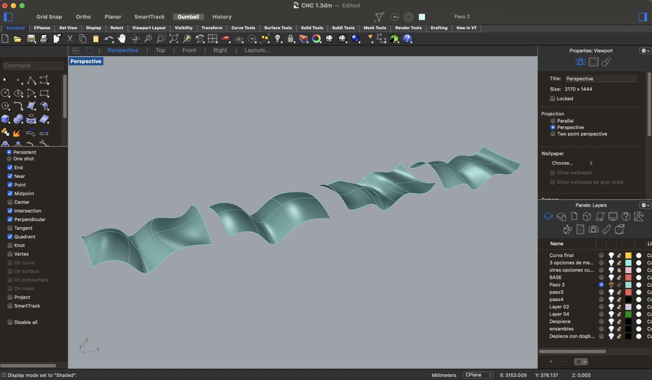
2:
Next, I traced different curves and with the 'loft' tool created surfaces that would help me achieve the desired organic curve. The 'loft' tool allowed me to blend between multiple curves to generate complex surface geometries.
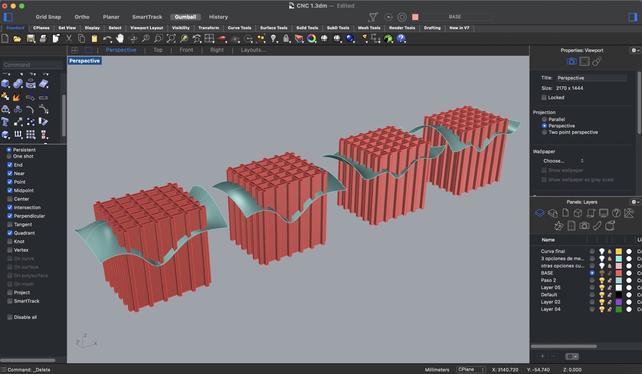
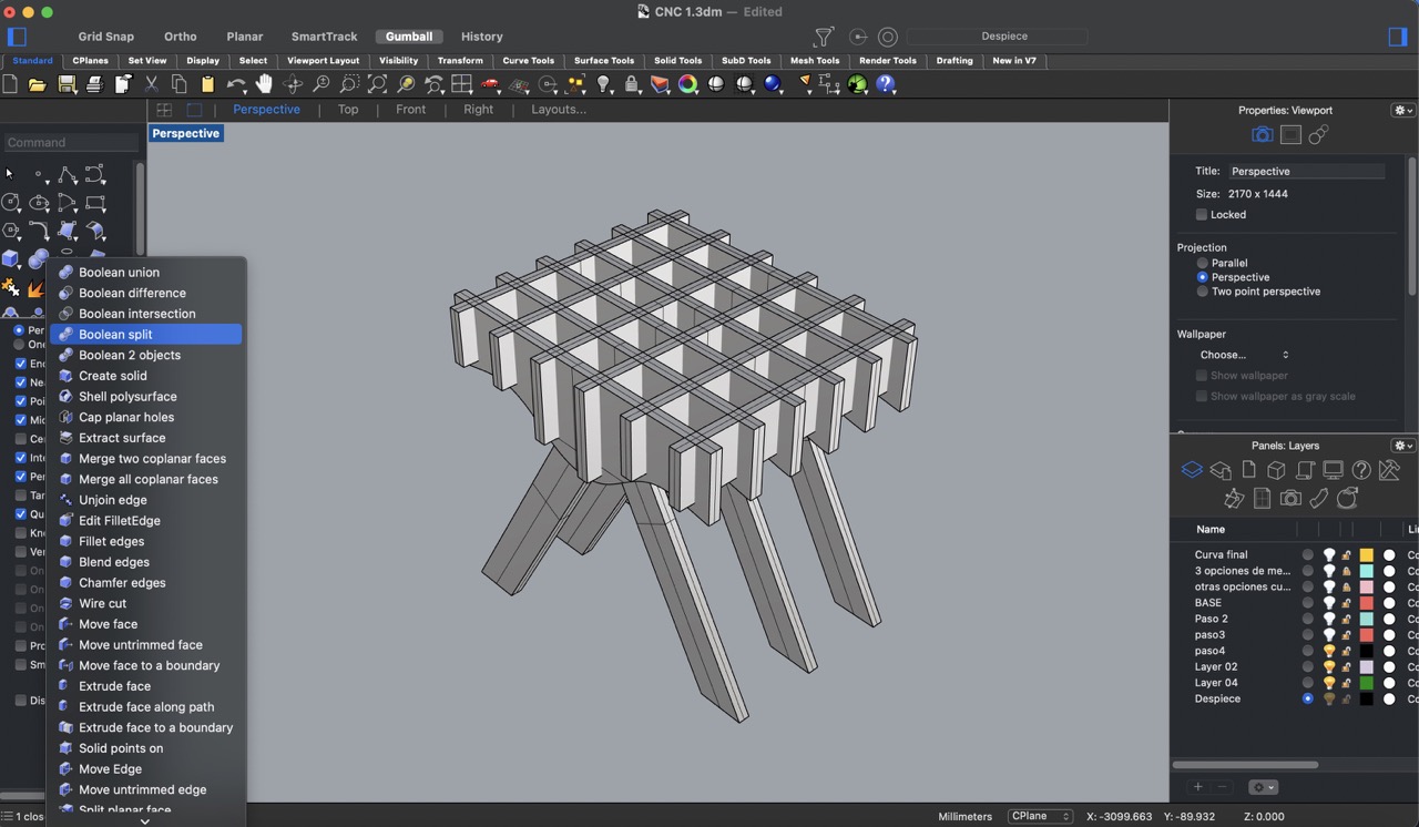
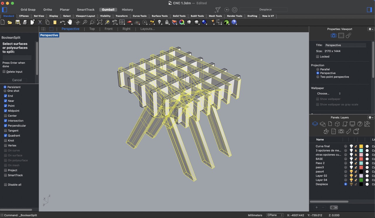
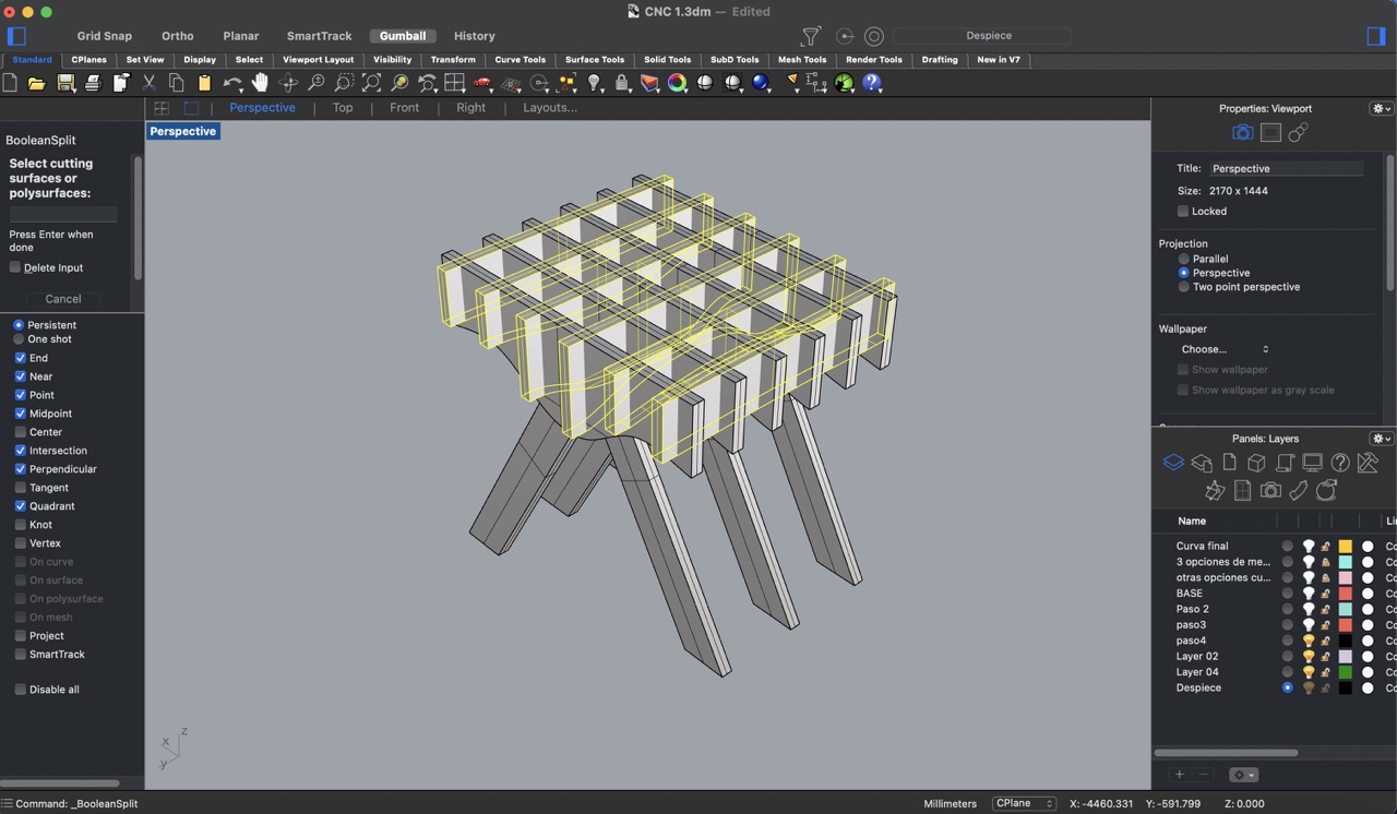
3:
After creating the surfaces, I used the 'Boolean split' tool to manipulate the geometries and obtain the desired shapes.
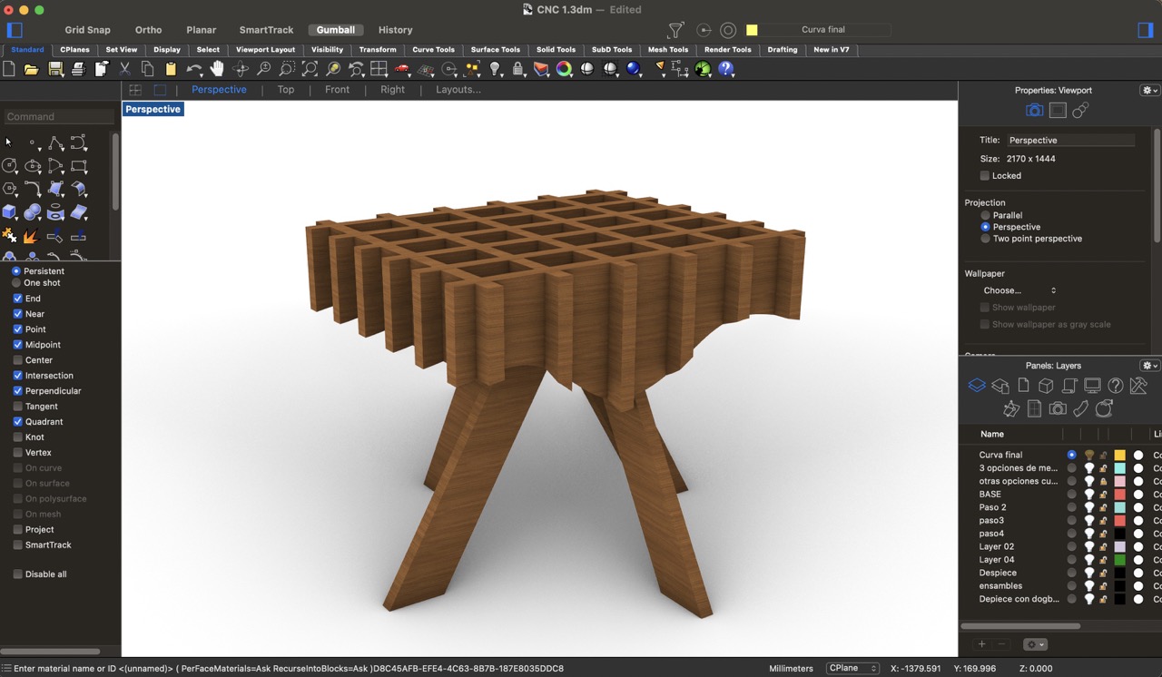
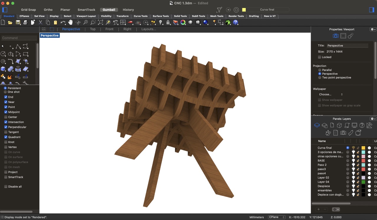
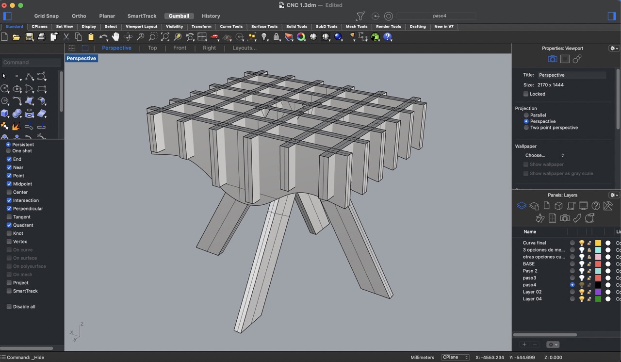
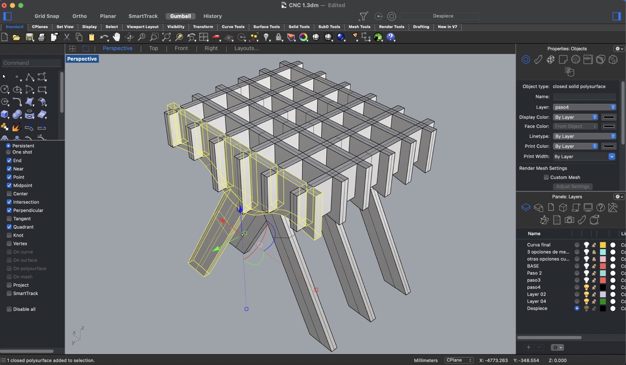
4:
Then, I choose my favourite and added four legs to provide support for the structure.
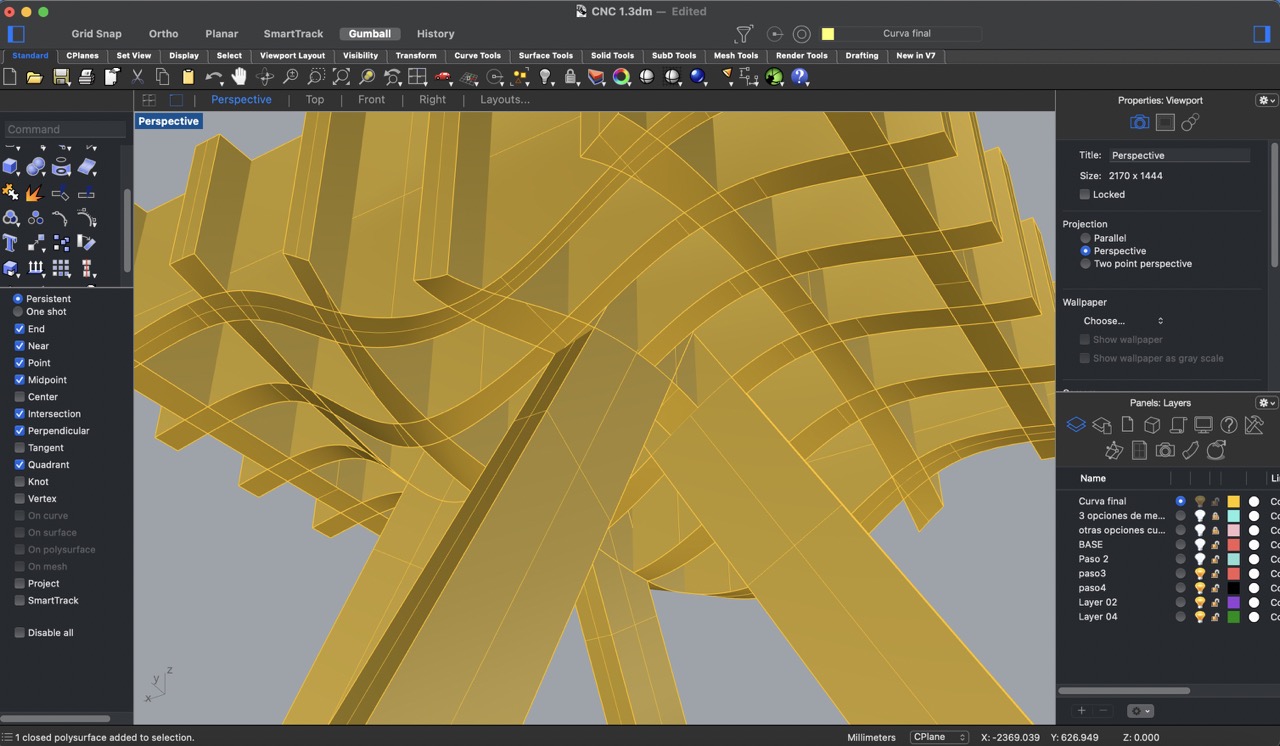
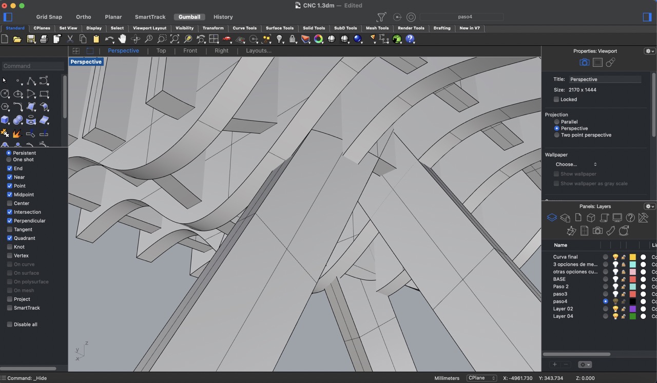
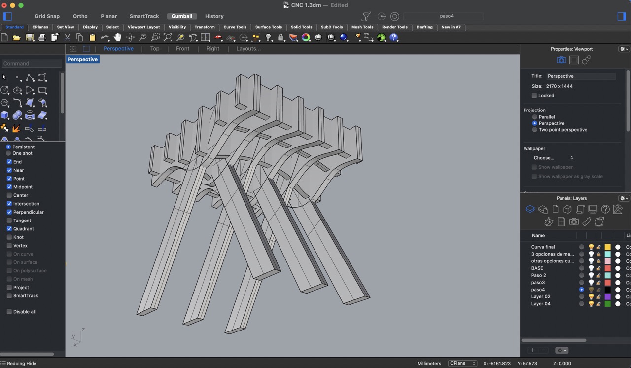
5:
Ups!! I encountered a problem, all of the edges are curved instead of having straight cuts. While it's possible to achieve curved edges using a CNC machine, the time required for cutting and carving each piece would be too extensive. Therefore, I decided that the best solution is to simplify each piece by making straight cuts instead of curved edges to expedite the manufacturing process.
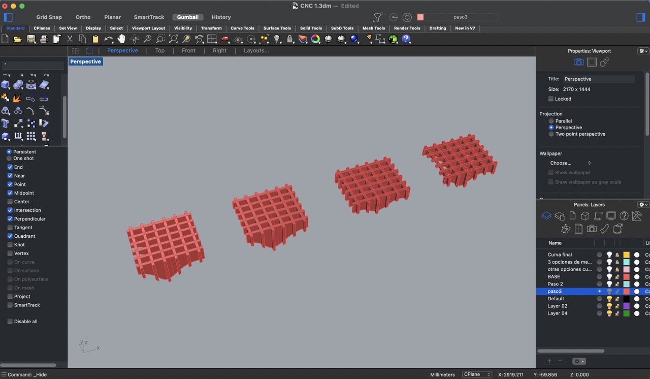
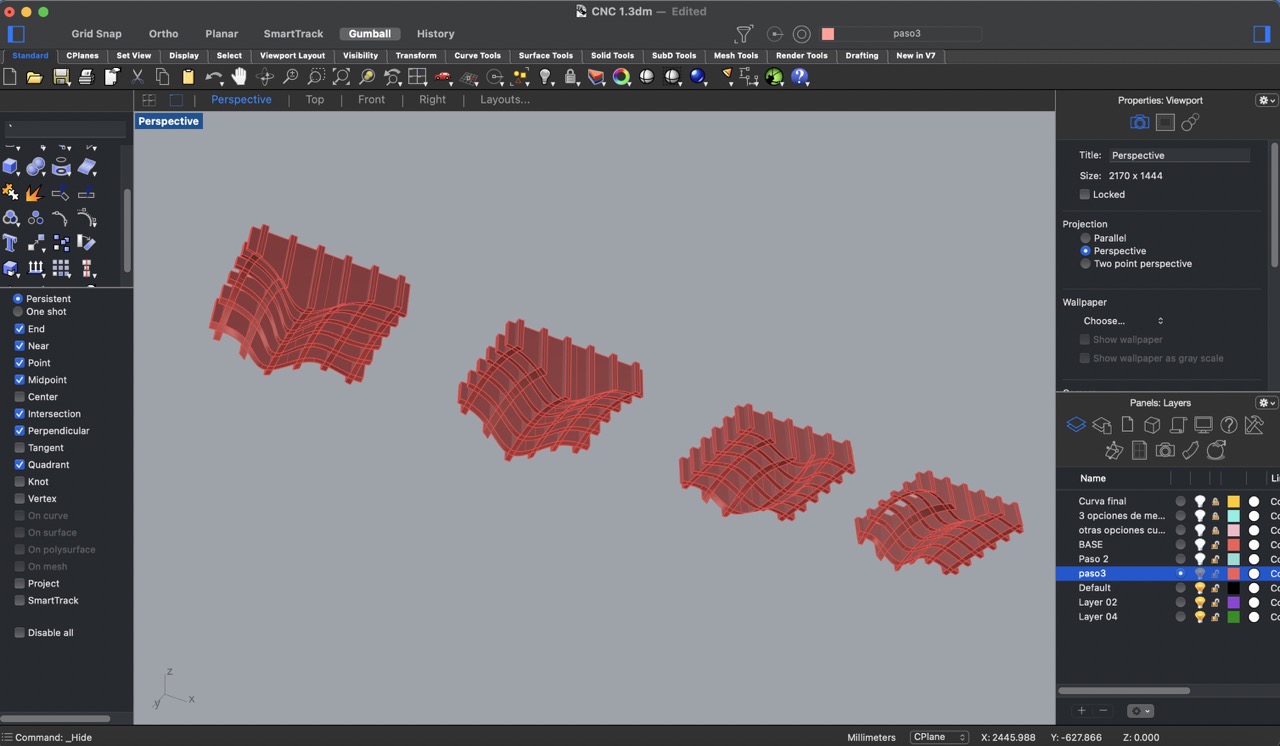
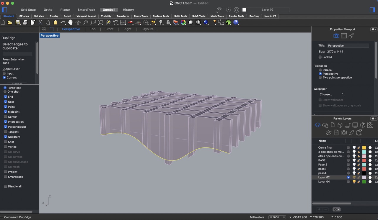
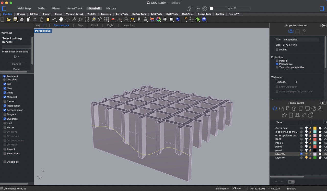
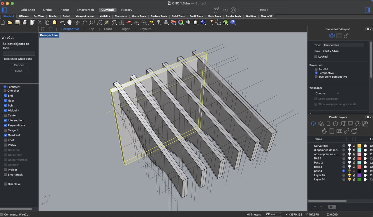
6:
To simplify the geometries, I started by duplicating the edges using the 'DupEdge' tool. Then, I created rectangular prisms with a 15 mm thickness and using the 'WireCut' tool, I cut out the rectangular prisms with the duplicated edges. I repeated this process for each of the horizontal panels shaded in gray.
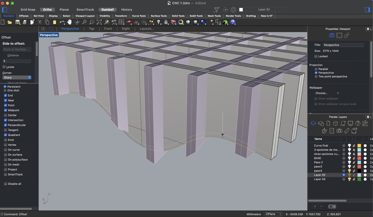
7:
I created a 10 mm offset from the duplicated edge to establish a margin for the simplified geometry.
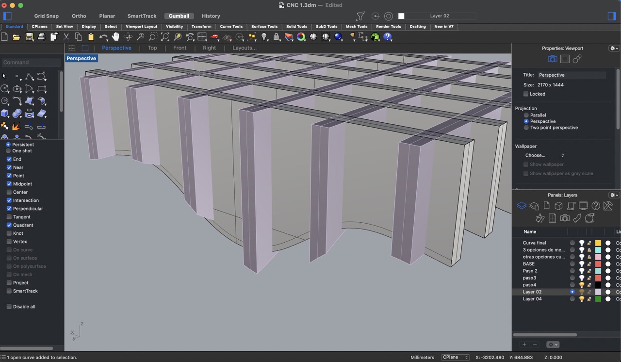
8:
To identify intersecting points and establish guidelines, I created lines where the vertical panels intersected the horizontal ones.
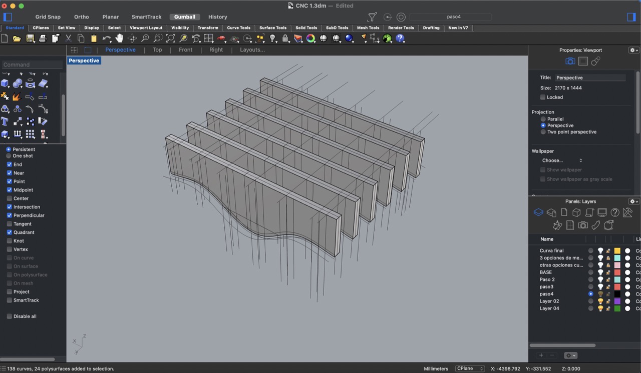
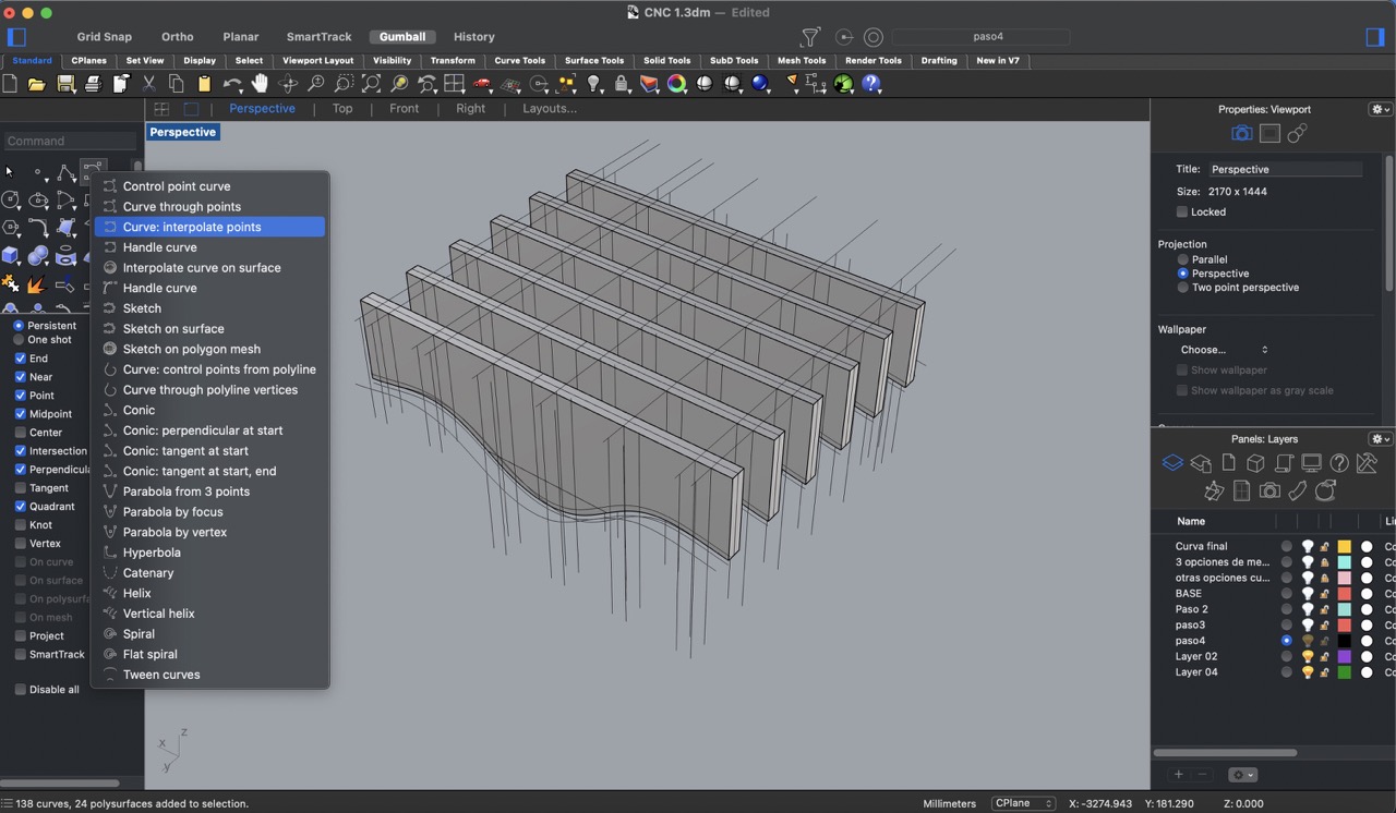
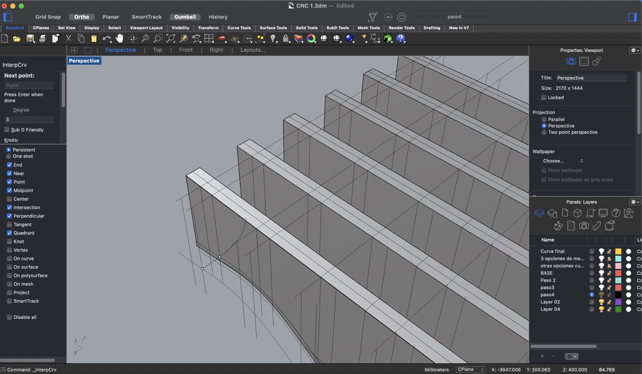
9:
Using the 'curve: interpolate points' tool, I generated curves connecting the intersecting points of the guides. This step was repeated for all panels.
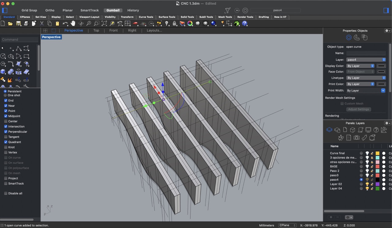
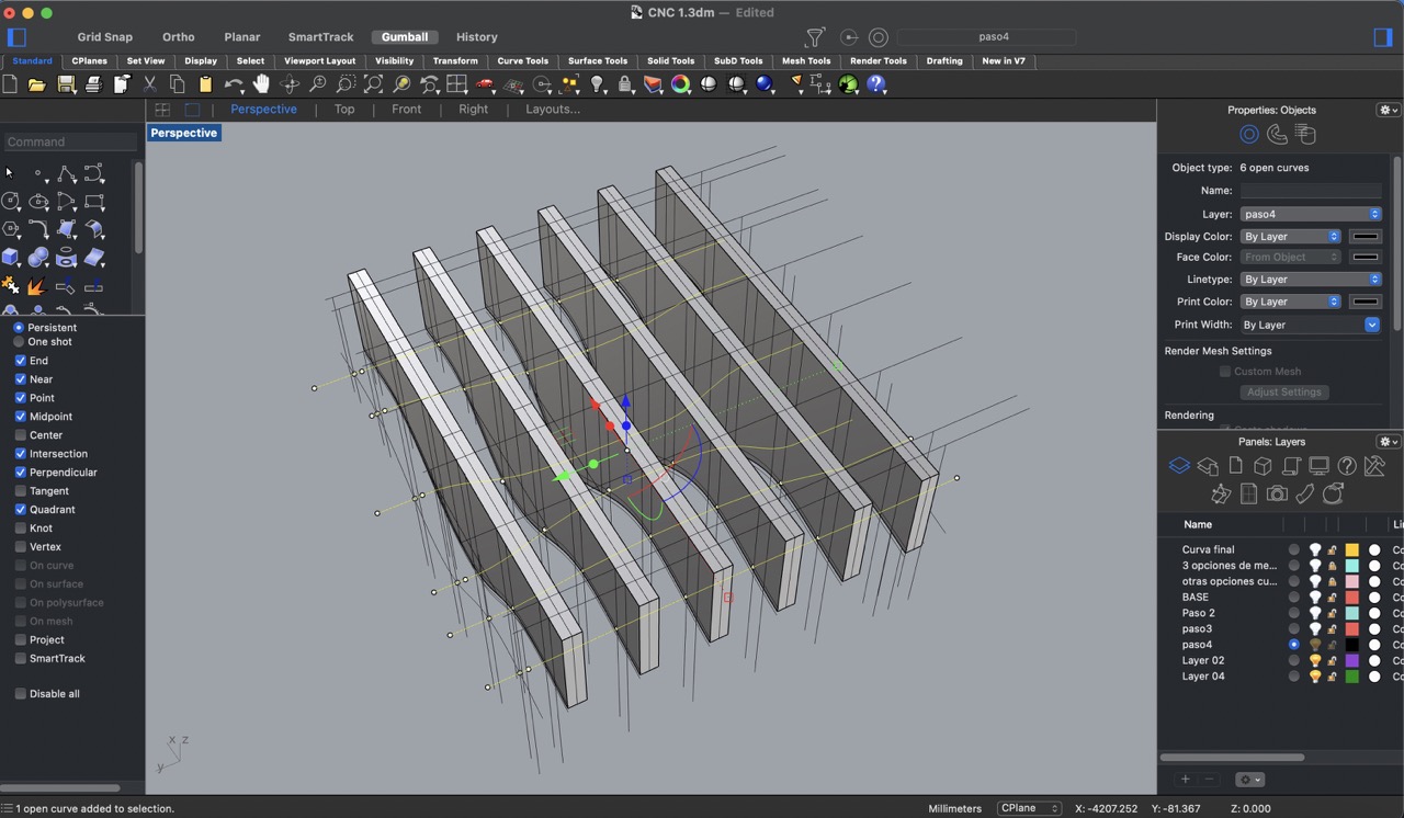
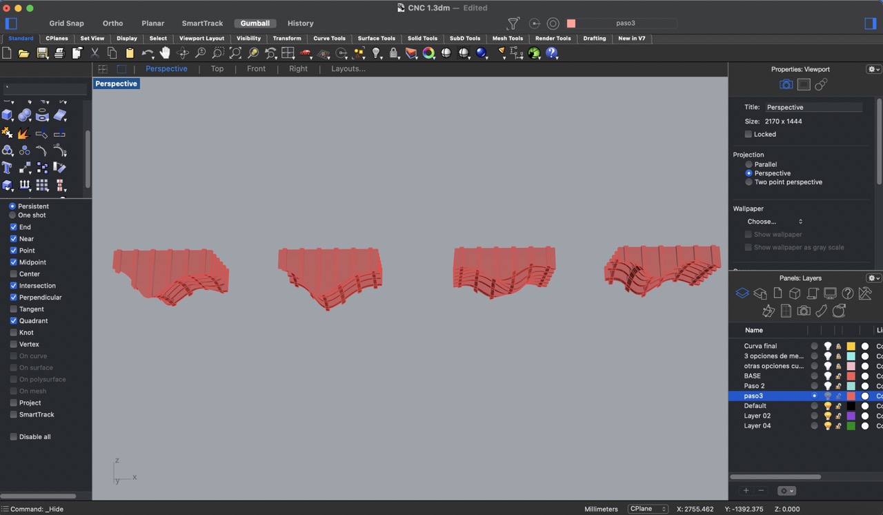
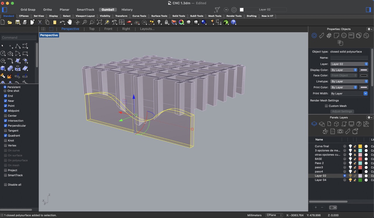
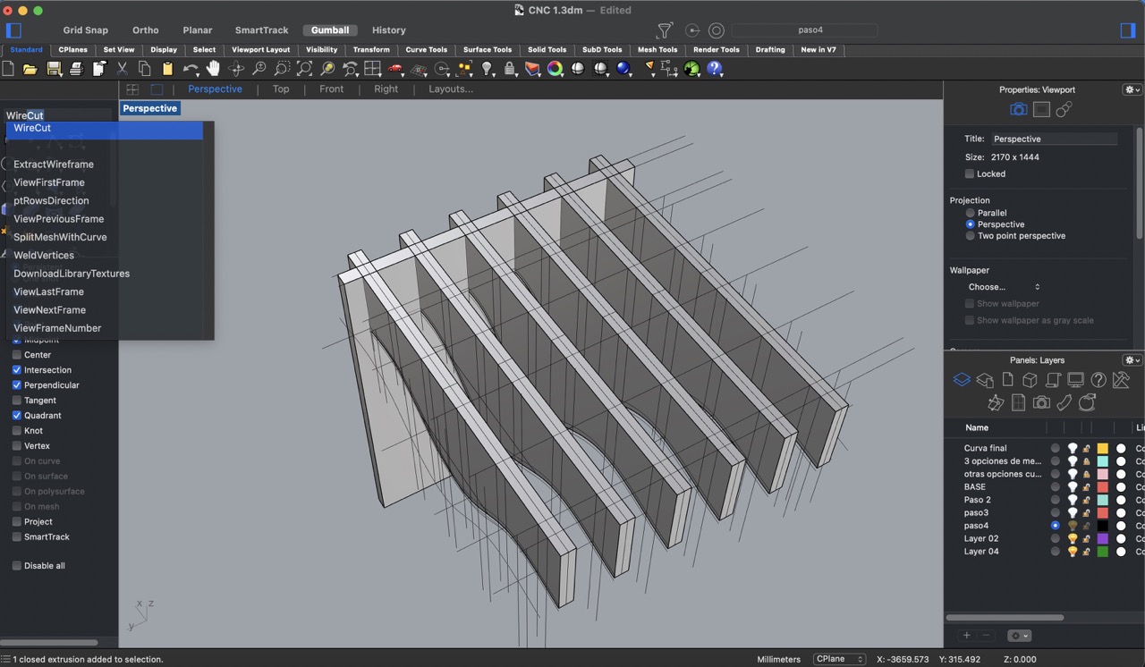
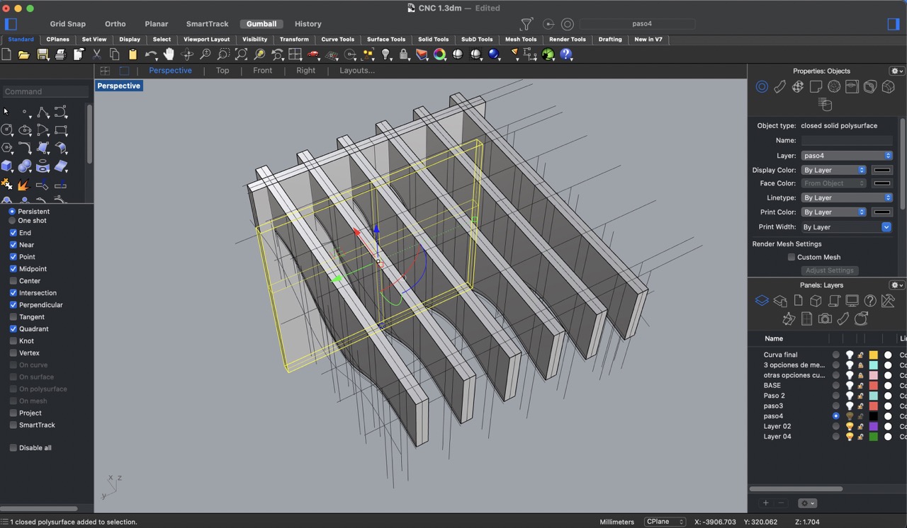
10:
I created rectangular prisms with a 15 mm thickness, and using the 'Wire cut' tool, I cut the geometry along the curves. This process was repeated for all vertical panels.
11:
Initially I had added 4 legs as the structure, but since the design changed, these were no longer viable.
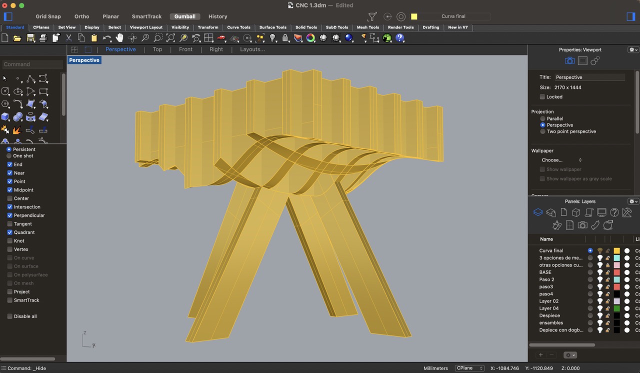
12:
Instead, I decided to add legs to all horizontal panels. Using the 'boolean union' tool, I merged the legs with the corresponding panels to ensure structural integrity.
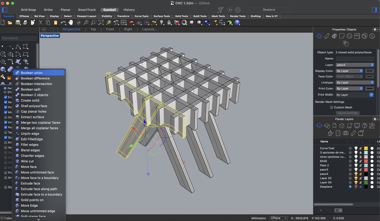
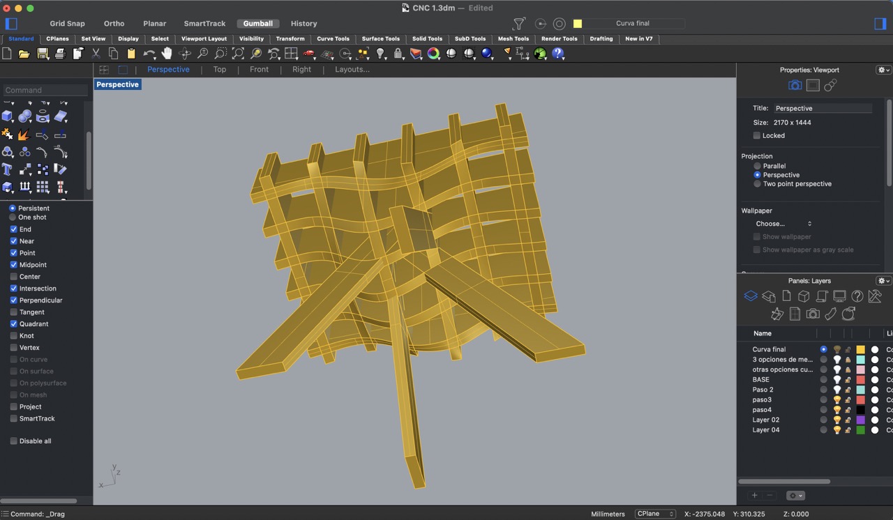
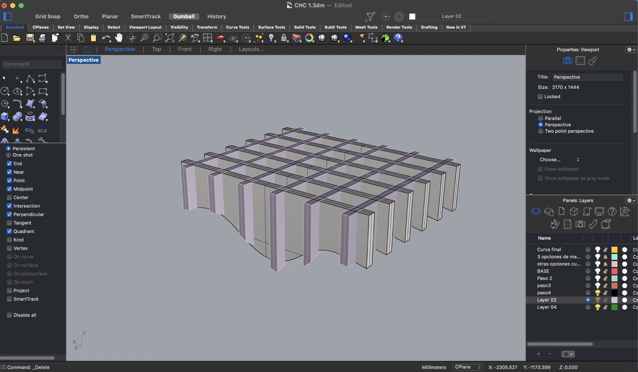
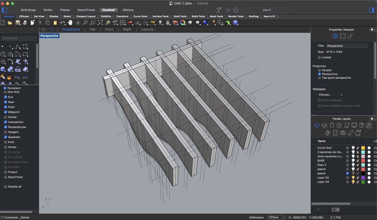
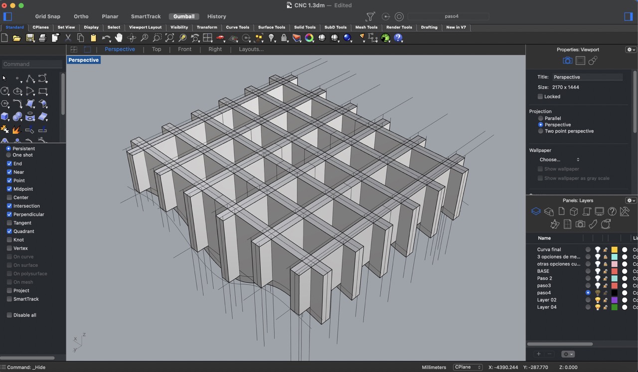
13:
Finally, I used the 'Boolean split' tool to cut the horizontal panels with the vertical ones, creating the necessary joints for assembly.
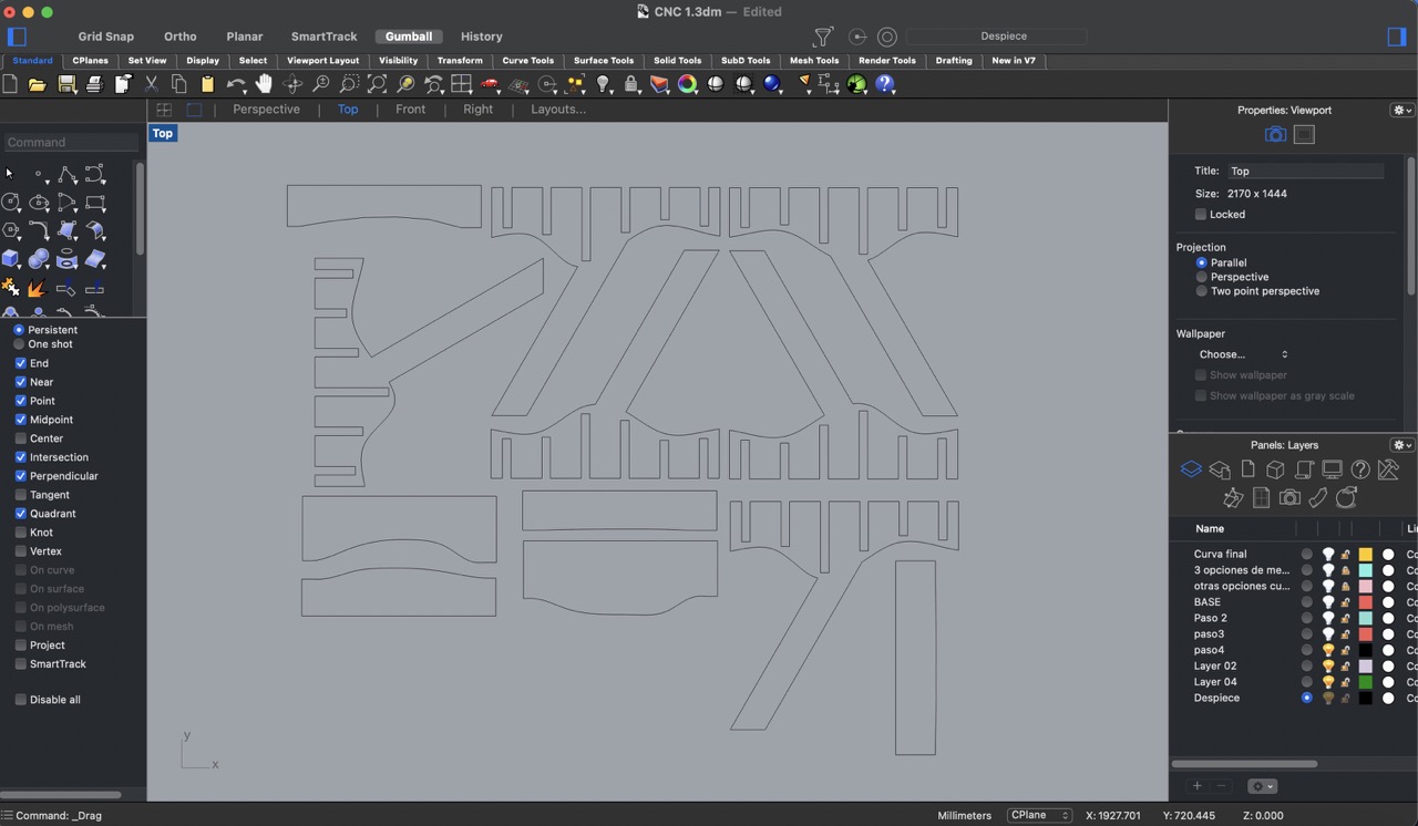
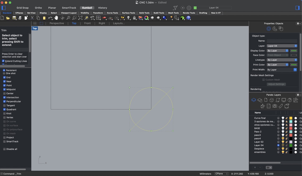
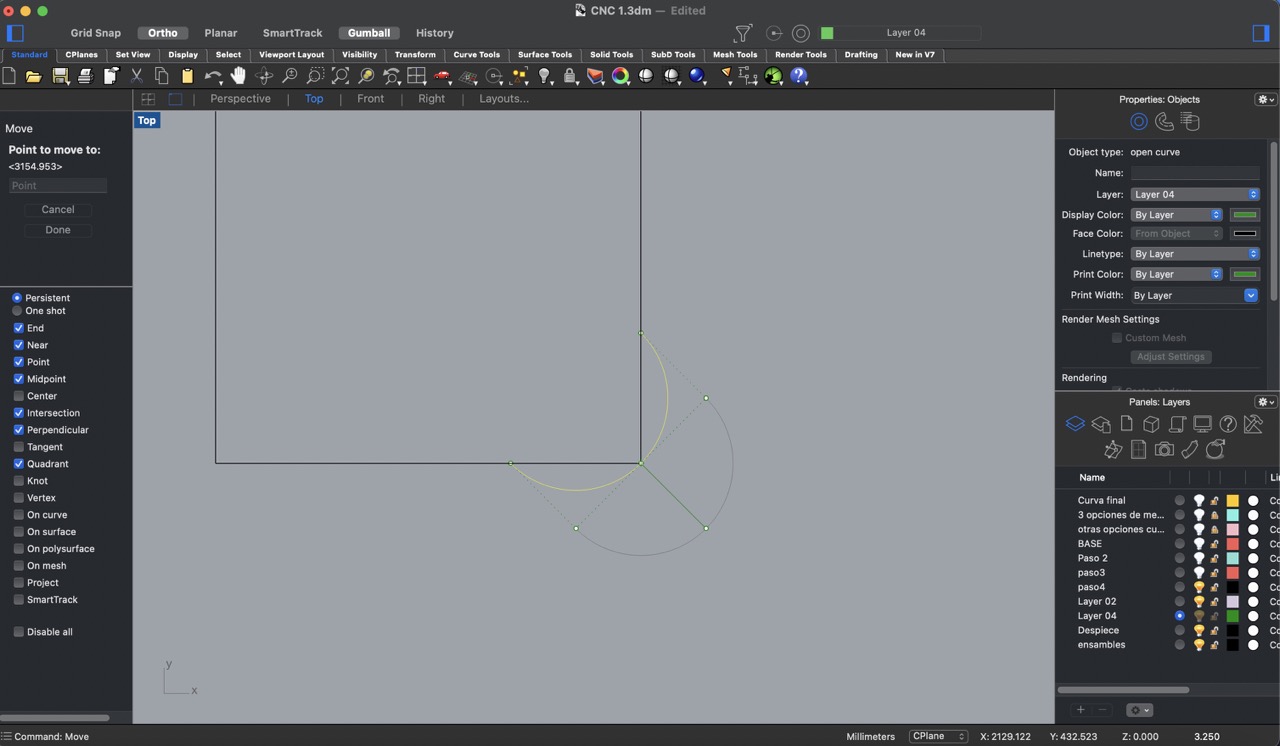
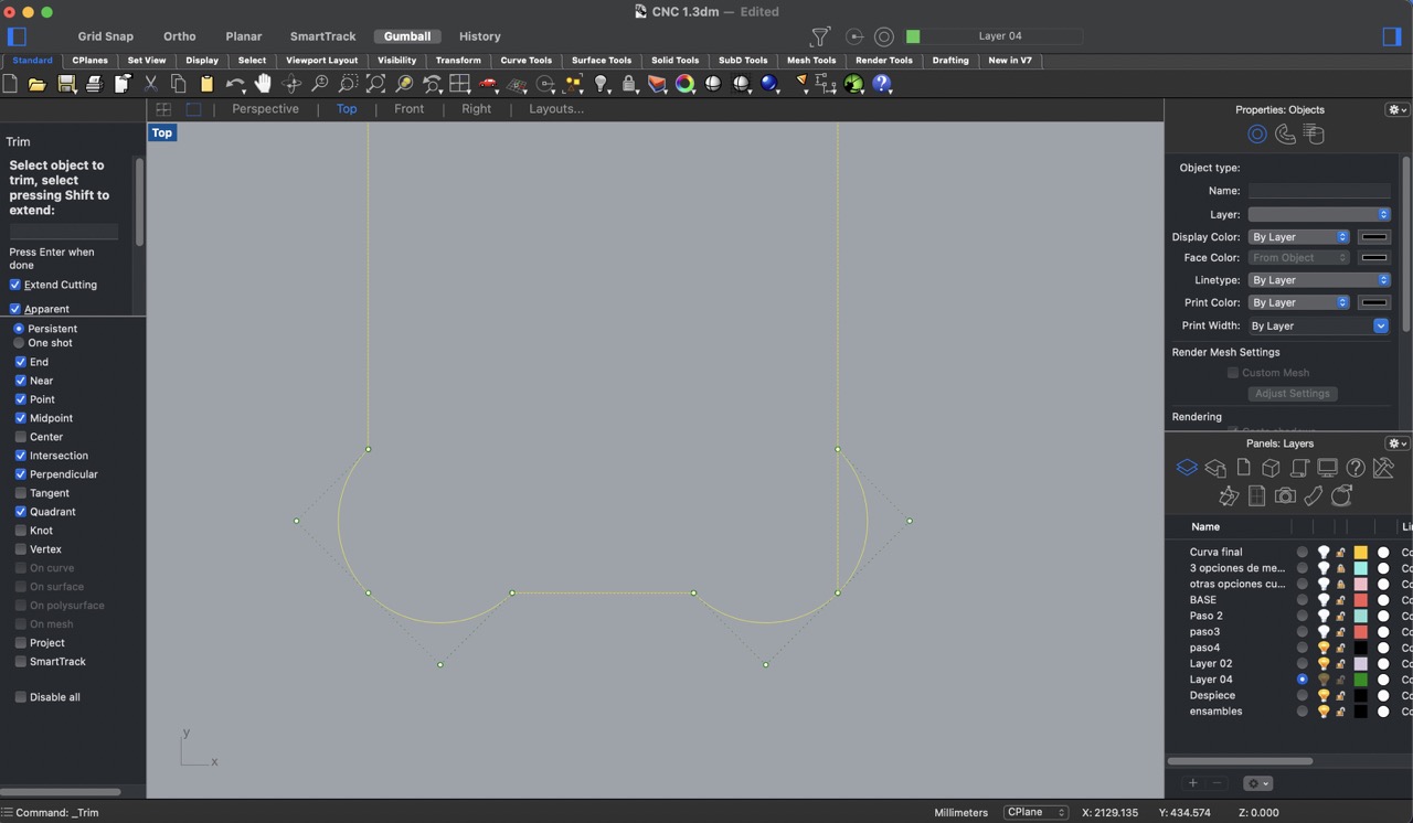
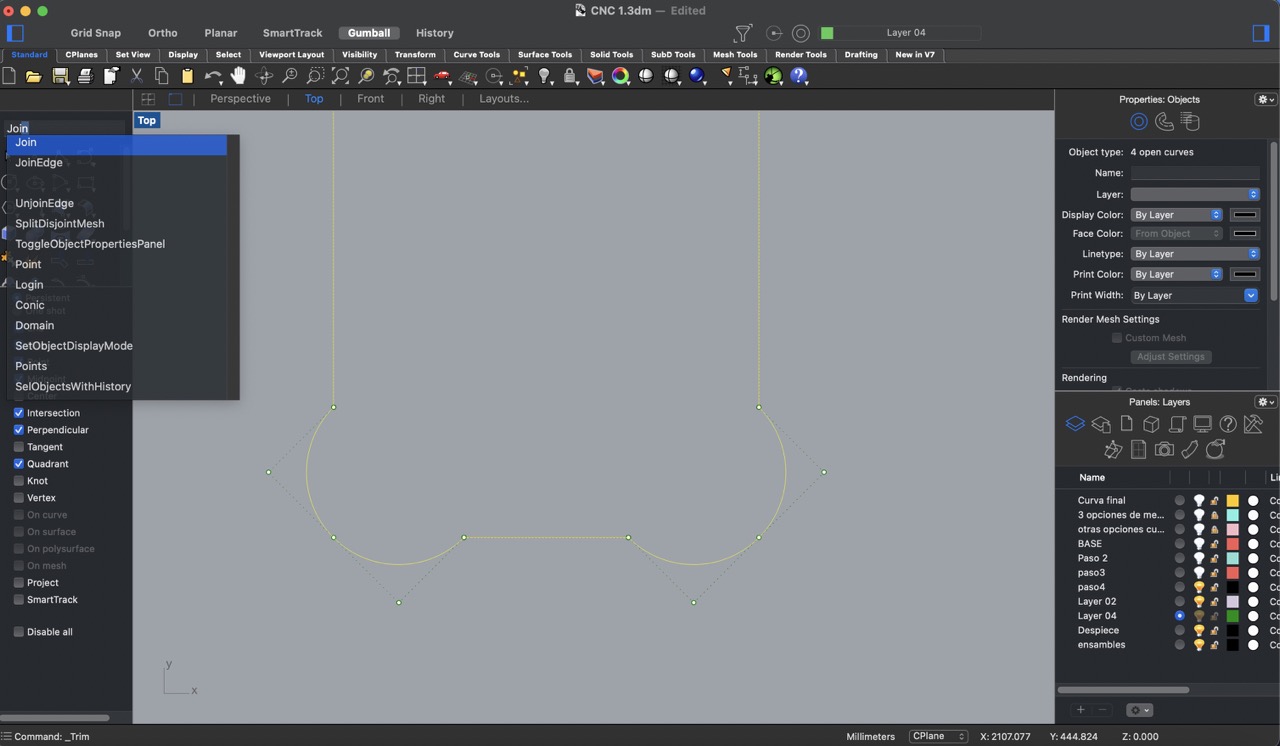
14:
To ensure that the pieces can be assembled properly, I added dog bones to the inside edges. I chose a circle with a diameter of 6.5 mm for the dog bones. This diameter accommodates the ¼” (6.35 mm) cutter I will be using, with a slight margin of space for ease of assembly. I created a circle with a diameter of 6.5 mm and then cut it in half to make them less noticeable, I then positioned these half-circles at the edge points of the inside edges. To clean up the design, I trimmed any extra lines or unnecessary geometry resulting from the dog bone placement. Finally, I joined all of the curves to ensure that the dog bones are integrated seamlessly into the design and ready for fabrication.

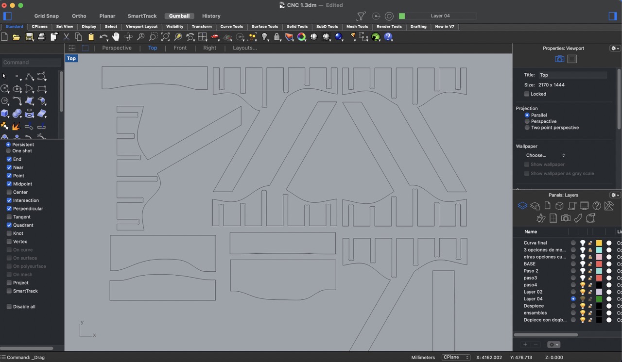
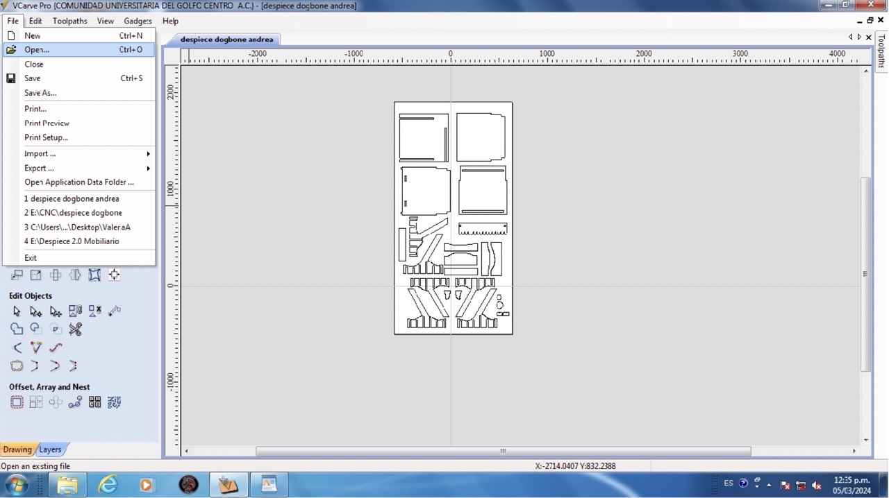
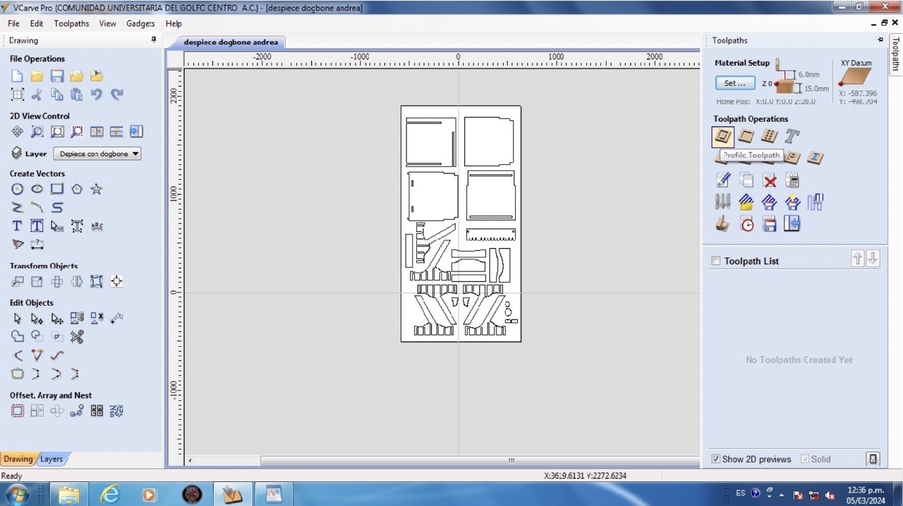
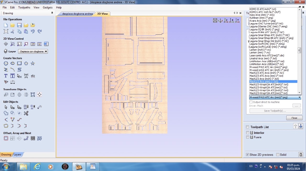
Using VCarve to create the cutting file
- To start I opened up my .dxf file in Vcarve.
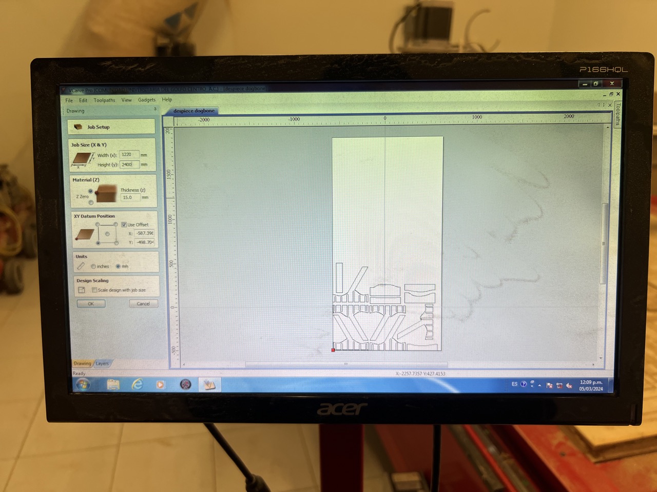
- Then, I input the dimensions of my material to cut, 1220 x 2440 mm. I also specified the material thickness, which is 15 mm, and set the starting position.
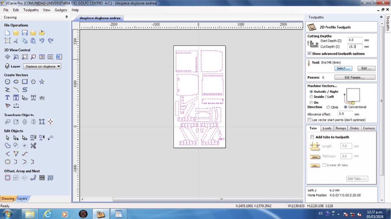
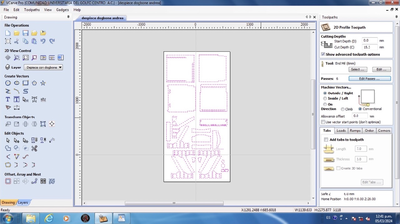
- I navigate to the toolpaths menu and choose 'Profile Toolpath,' which outlines the cutting path.
- I specified the cutting depth parameters. For instance, I set 'Start Depth' to 0 mm and 'Cut Depth' to 15.3 mm, including an extra 0.2 mm for thorough cutting.
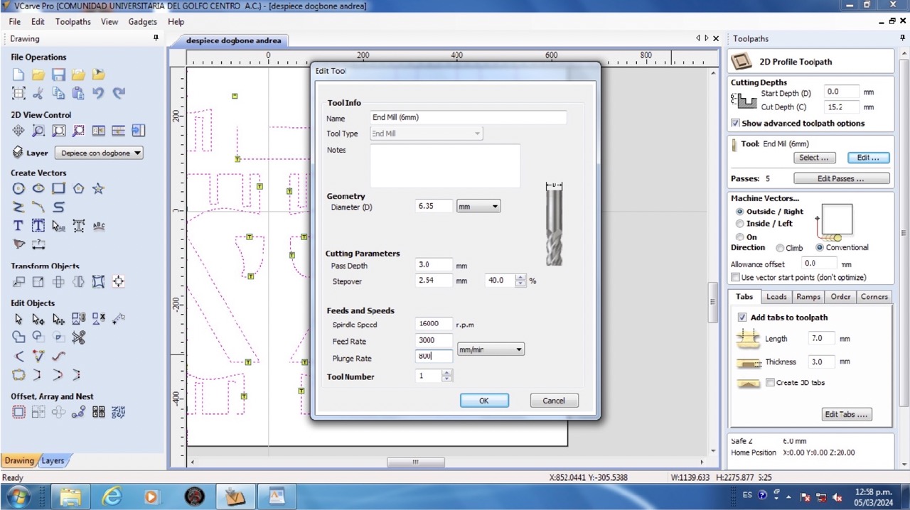
- I clicked on 'Select' under the 'Tool' section and adjusted parameters such as tool diameter (6.35 mm), spindle speed (16,000 rpm), feed rate (3,000), and plunge rate (800).
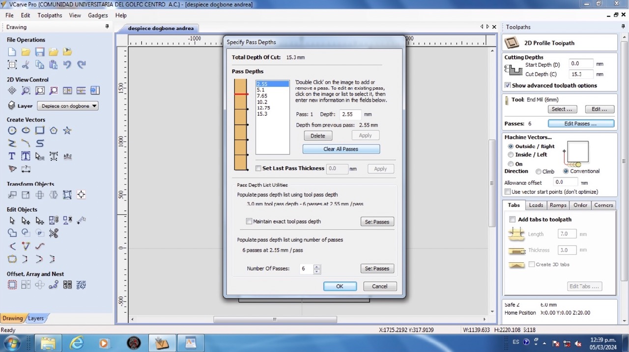
- I determined the number of passes needed, which in my case is 6 passes, for cutting.
- Under ‘Machine Vectors’ I choose 'Outside' cut to maintain the specified dimensions.
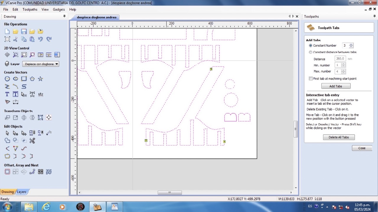
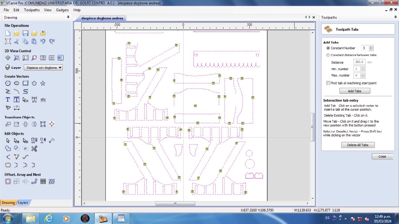
- I added tabs to my geometries to secure the design during cutting, it is recommended to use at least 3 tabs to prevent movement. Tip: avoid placing them near joints to prevent complications in assembly.
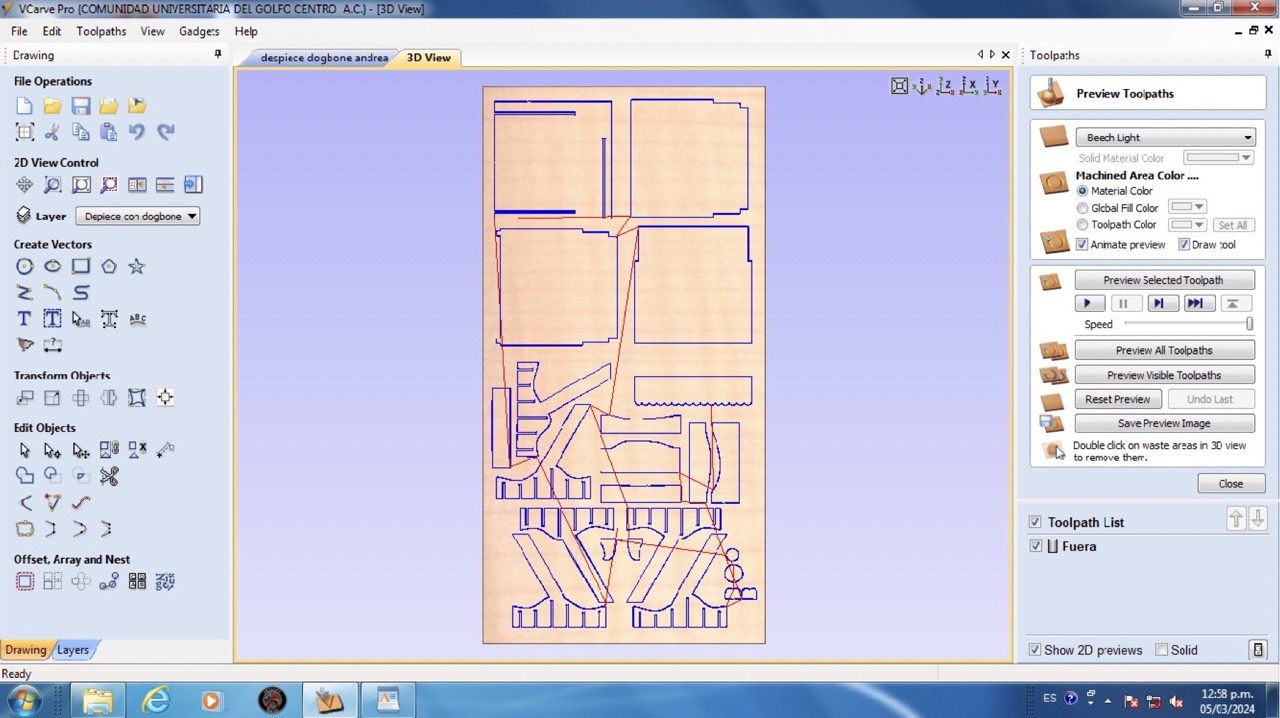
- Once the settings were configured, I previewd the toolpaths to visualize the cutting process and assess if any modifications are required. I also reviewed the estimated cutting time.
- Finally, I saved the file in the appropriate format for my CNC machine, 'Mach2/3 Arcs (mm) (*txt)'.
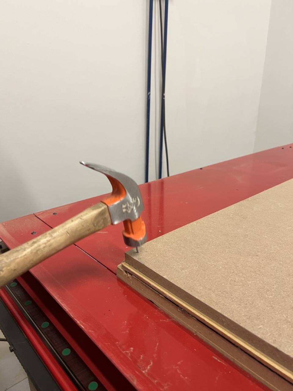
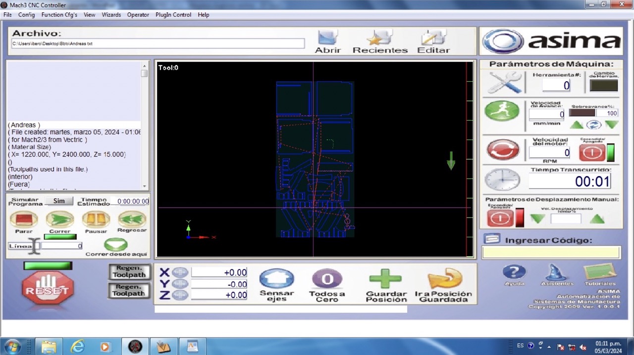
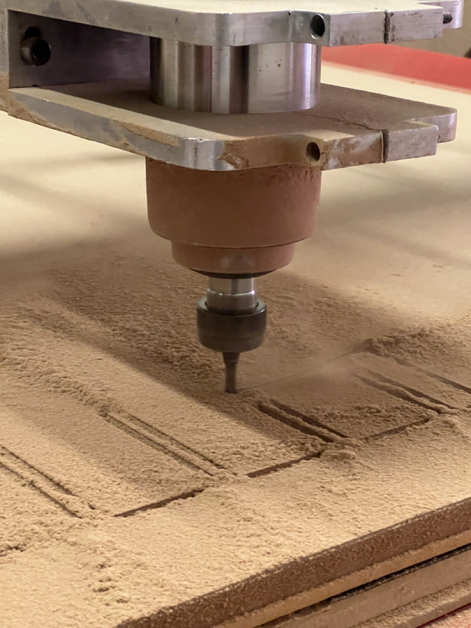
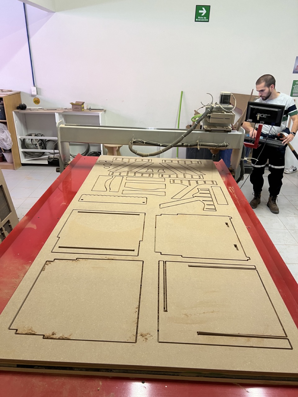
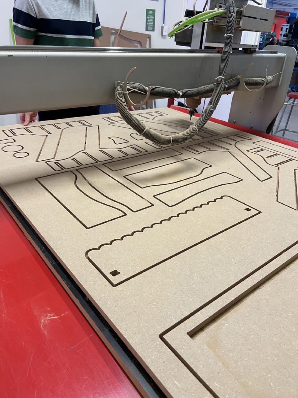
Cutting with the CNC machine
- Initially, I secured my MDF table with nails at each corner to prevent any movement of the material during cutting.
- Next, I inserted my USB drive containing the recently saved cutting file from Vcarve.
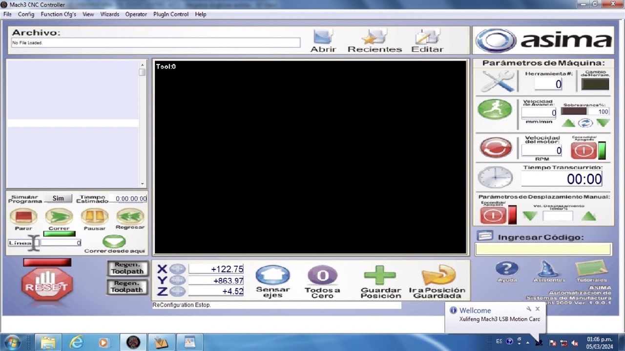
- I launched the cutting software, 'Mach3 CNC Controller,' and proceeded to upload my cutting file.
- After uploading the file, I positioned the CNC machine's axis to the lower left corner of the material and established this point as the origin.
- With the setup complete, I initiated the cutting process by pressing the 'play' button, allowing the CNC machine to cut my design.
- Once finished, I removed any residual dust and debris using a vacuum cleaner.
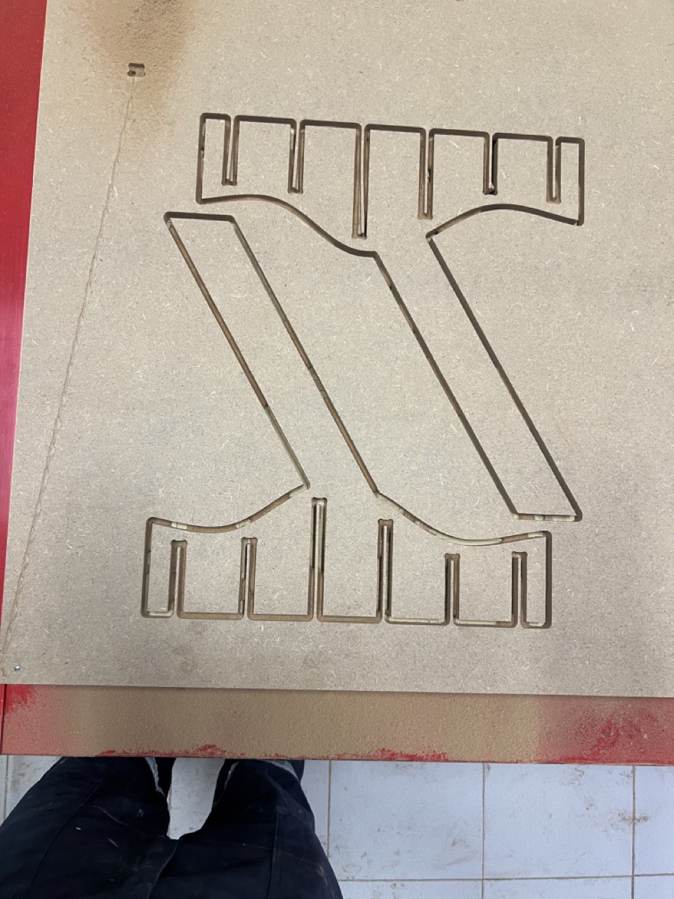
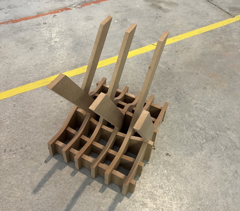
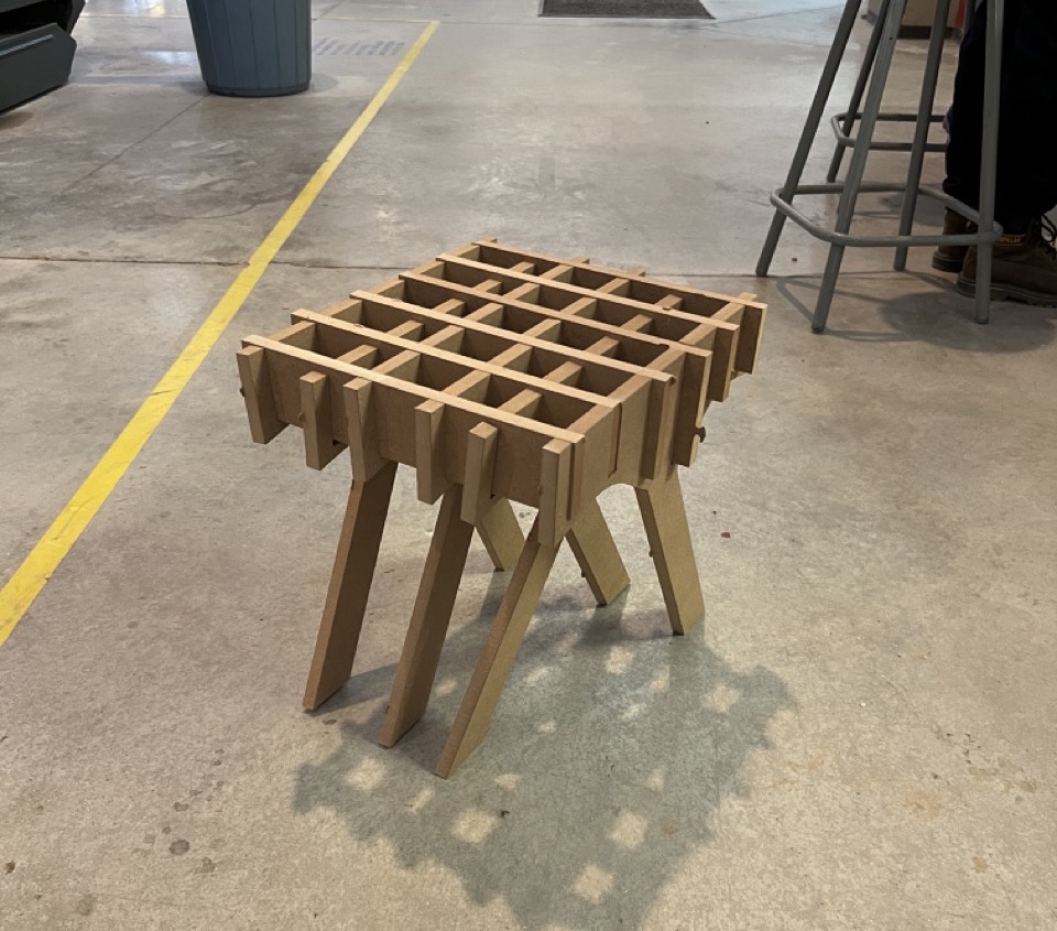
Assembly
Files
Final thoughts
Reflecting on the process, I encountered some challenges, initially, I underestimated the importance of engraving or marking each piece to identify them. As a result, when I had all the pieces ready for assembly, I faced significant difficulty in determining their correct order. I believe that to improve the design, I would make the joints on both pieces to ensure better alignment and structure for the table.