Networking and communications
This week's assignment is to establish communication between two boards. For the group assignment, we explored how to use the UART protocol to connect two different projects. For my individual assignment, I decided to experiment with a different protocol to broaden my experience and understanding in networking and communication. Link to the group's assigment.
What does networking and communication mean?
Networking and communication between microchips involve the exchange of data and commands between multiple microcontrollers or microprocessors. This allows them to work together, share information, and coordinate actions. Common protocols for this communication include UART (Universal Asynchronous Receiver-Transmitter), I2C (Inter-Integrated Circuit), SPI (Serial Peripheral Interface), and CAN (Controller Area Network).
Protocols for communication
Protocols of communication are standardized rules and conventions that define how data is exchanged between devices in a network. They specify the format, timing, sequencing, and error-checking mechanisms for data transmission, ensuring that different devices can communicate reliably and efficiently. The following chart shows the common protocols used.
| Protocol | Description | Wires | Speed | Use cases |
|---|---|---|---|---|
| UART | Universal Asynchronous Receiver-Transmitter; used for serial communication between devices. It uses two wires (TX and RX) for data transmission. | 2 (TX, RX) | Low to medium (typically up to 1 Mbps) | Simple point-to-point communication, GPS modules, Bluetooth modules |
| I2C | Inter-Integrated Circuit; a multi-master, multi-slave, packet-switched, single-ended, serial communication bus. It uses two wires (SDA and SCL) for data transmission. | 2 (SDA, SCL) | Low to medium (typically up to 3.4 Mbps) | Communication between sensors, RTCs, EEPROMs, and microcontrollers |
| SPI | Serial Peripheral Interface; a synchronous serial communication interface used for short-distance communication, primarily in embedded systems. It uses four wires (MOSI, MISO, SCLK, and SS) for data transmission. | 4 (MOSI, MISO, SCLK, SS) | High (up to 50 Mbps or more) | High-speed communication between microcontrollers, ADCs, DACs, and other peripherals |
I2C
Using the I2C protocol for a basic example of communication and networking was a good idea because I2C is simple to implement, uses only two wires, and supports multiple devices on the same bus. This makes it ideal for beginners to learn and experiment with inter-device communication in a straightforward and scalable manner.
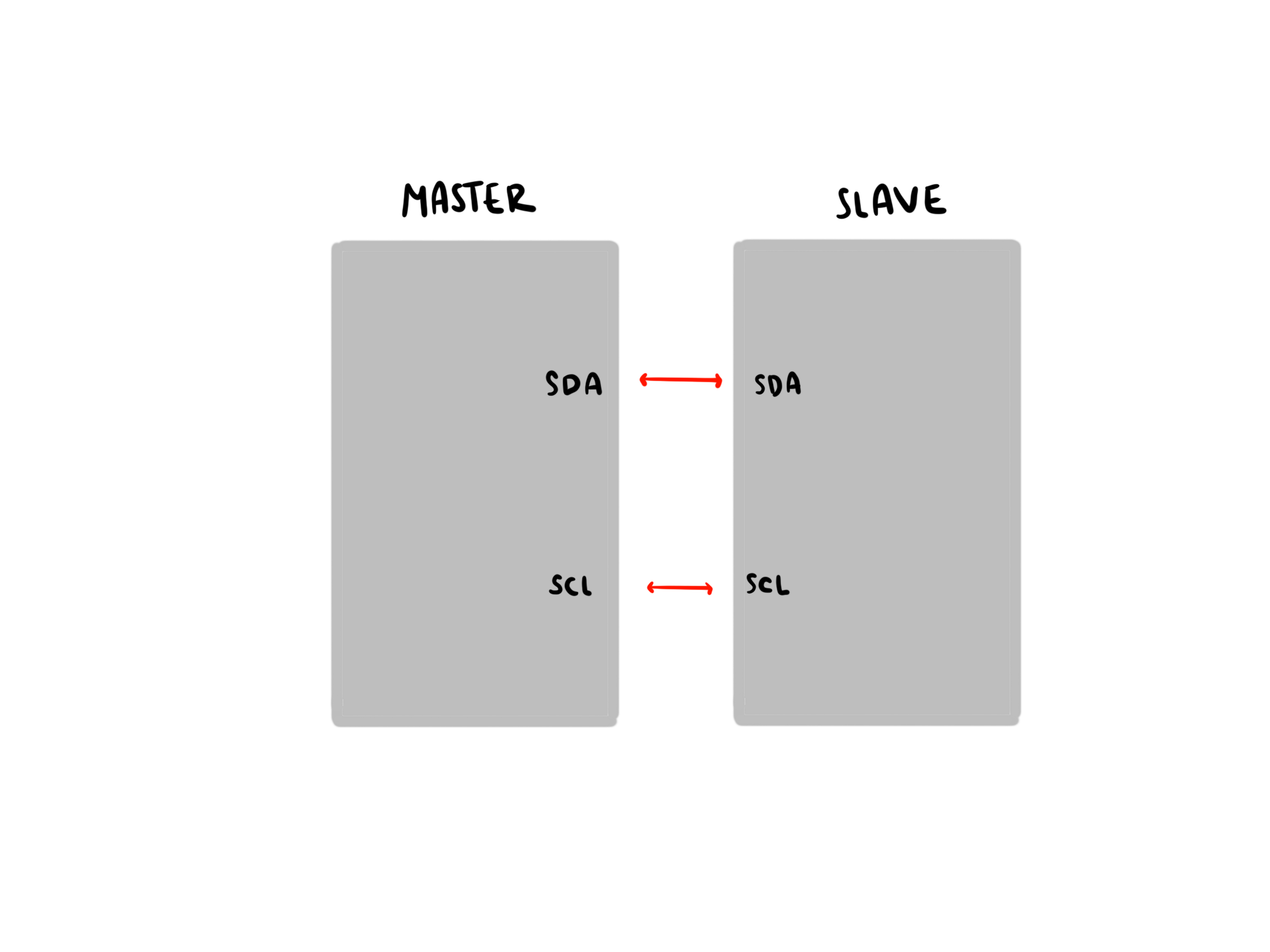
Xiao rp2040
For this assigment I used two Xiaos rp2040. The process of making it was explained in Week 4

Programming
Test 1
First, I conducted a test by sending a message from the master to the slave to understand how the I2C protocol works and to correct any mistakes if needed. I did the programming in Arduino IDE and used different ports of my computer for each PCB. I created two separate sketches, one for the master and another for the slave.
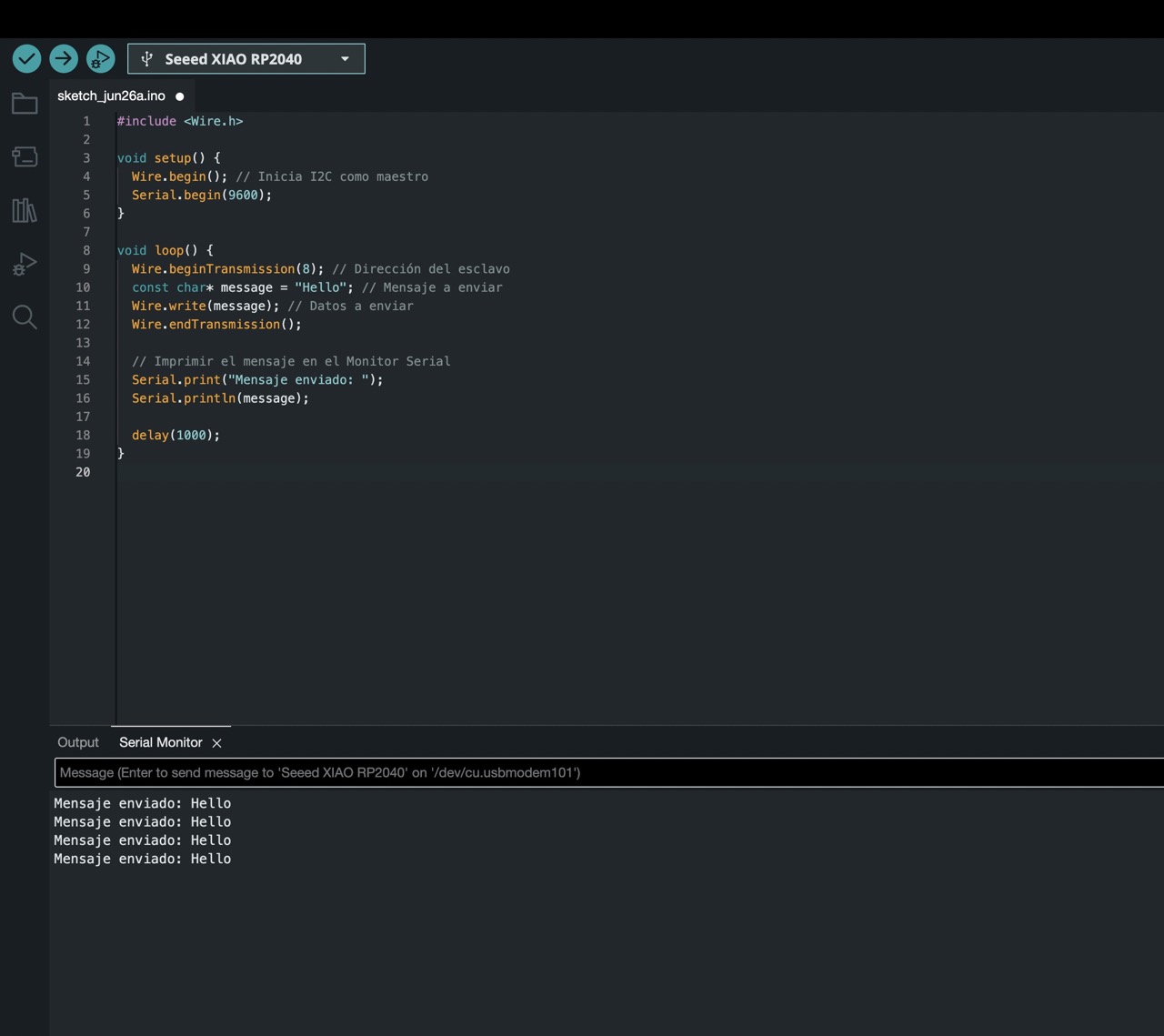
This test helped me confirm that the cables were connected correctly and that communication between the two microchips was possible.
Controlling an LED with a button
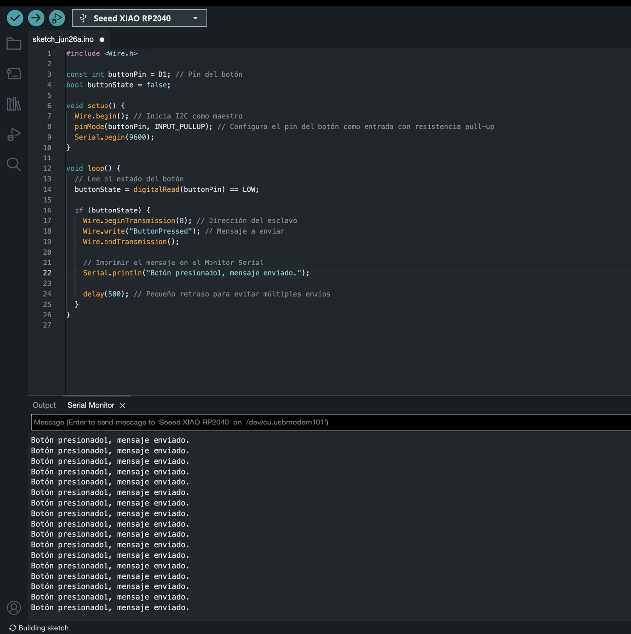
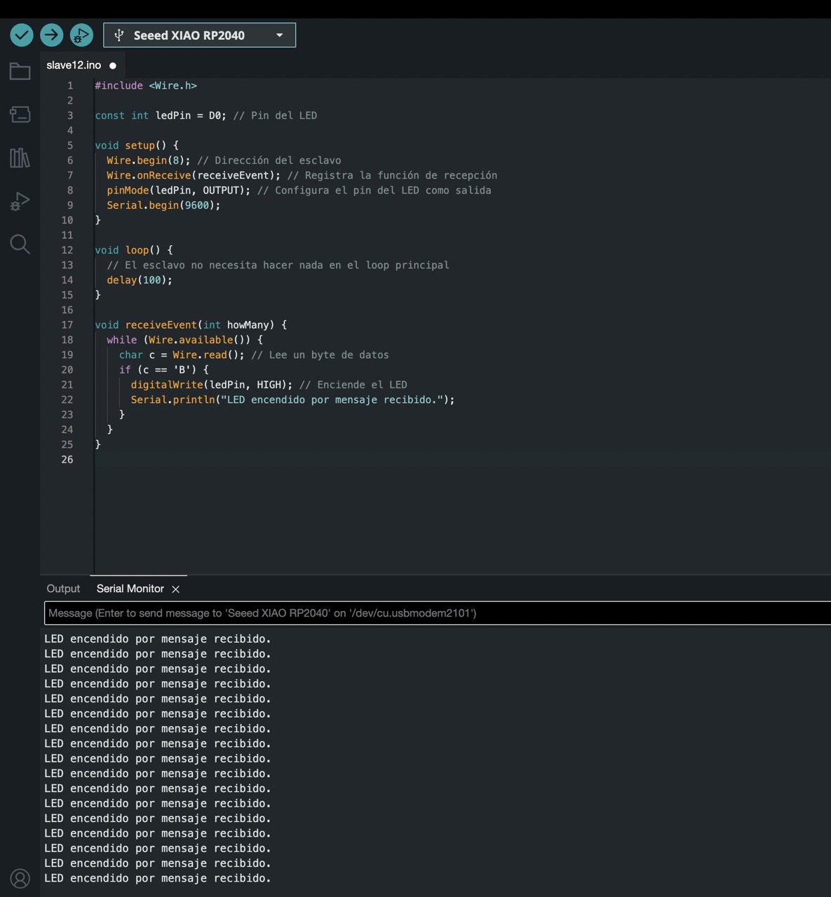
Once I confirmed that the communication worked, I decided to program the master chip so that when the button on the PCB was pushed, an LED on the other PCB would light up.
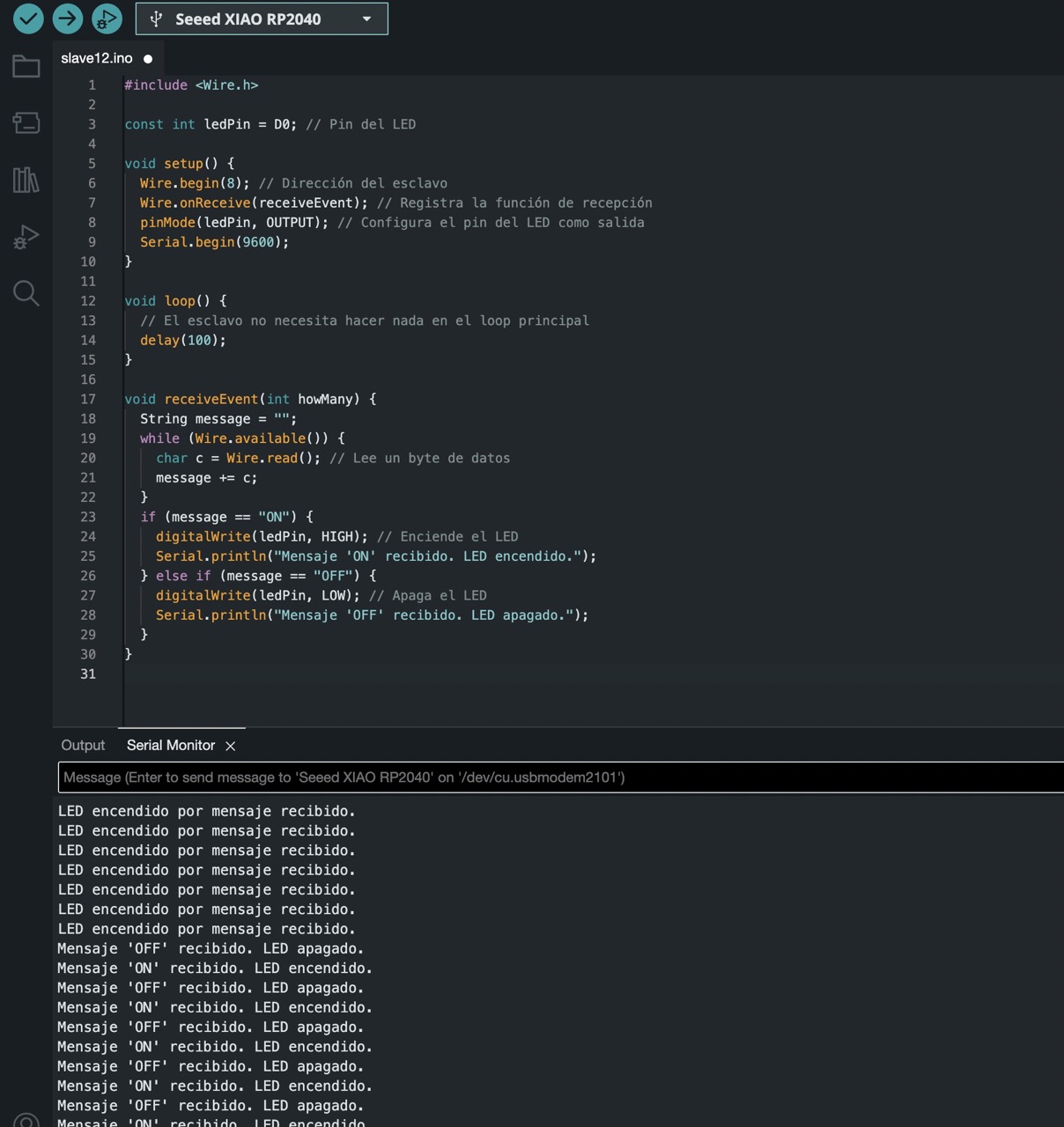
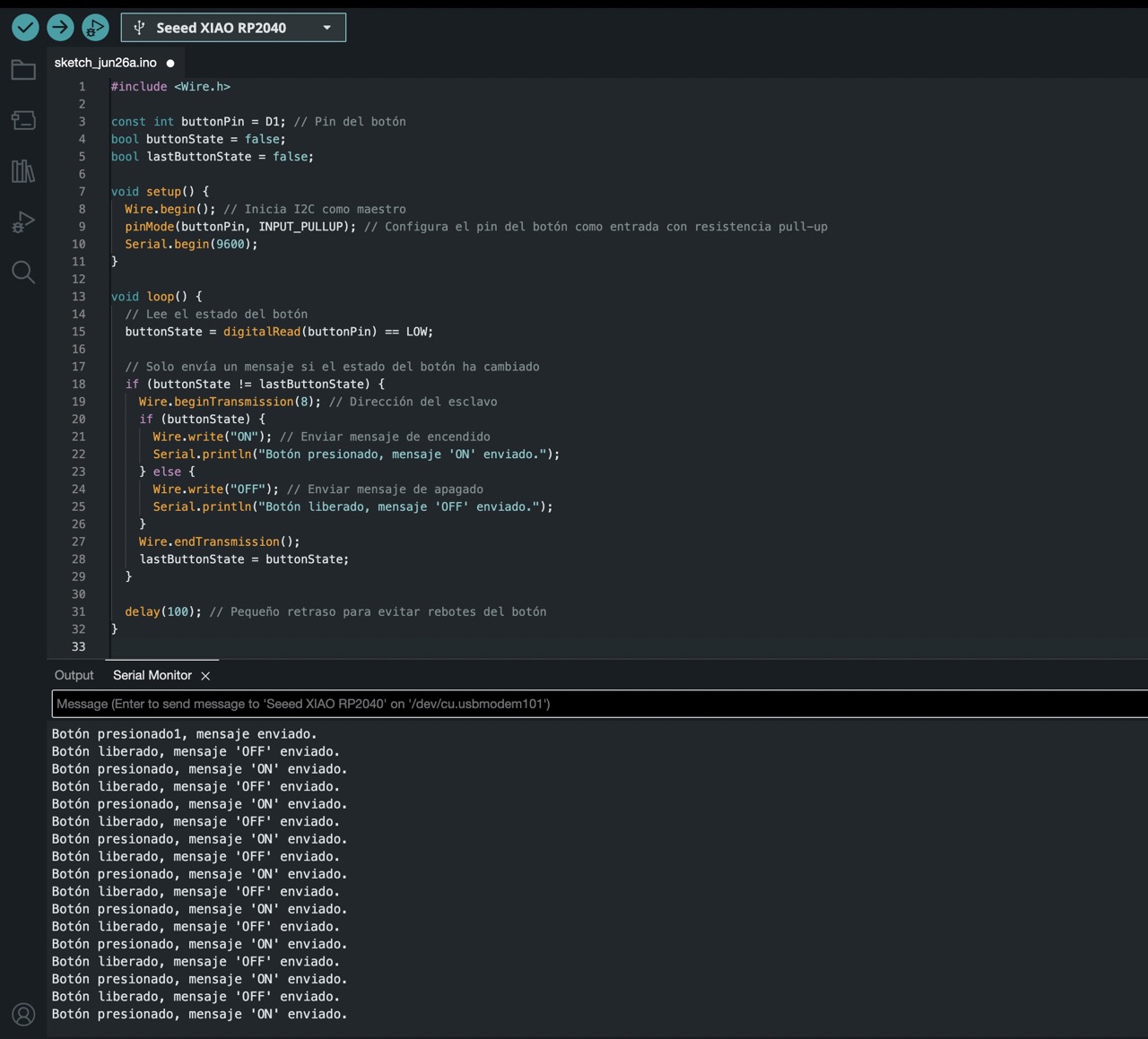
For this, I also created two different sketches. The following photos show the two codes.

Result
Nevertheless, this code resulted in the LED being turned on the whole time because the master's code was continuously sending a message that the button was pushed. So, this first attempt didn't quite work.
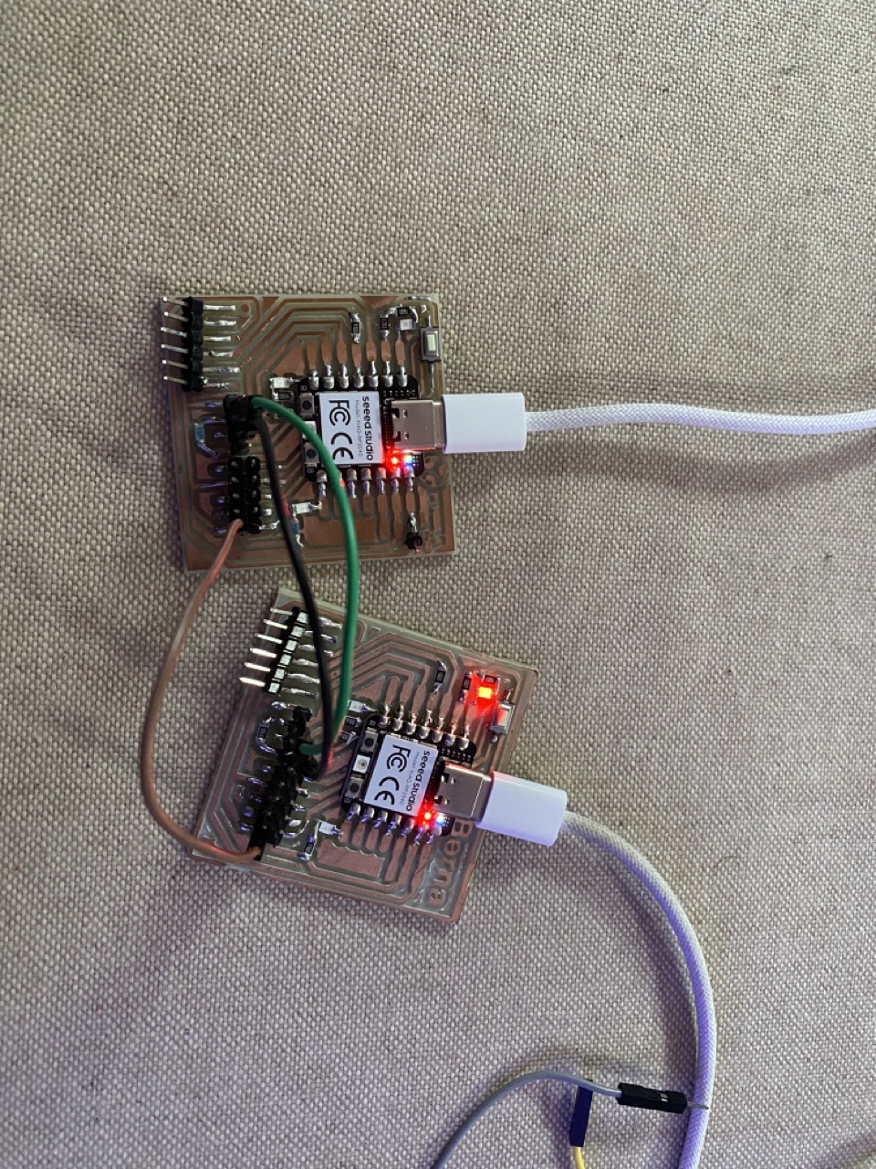
Second try
For the second attempt, I adjusted the master's code so that when the button was not being pushed, it would send an OFF message, and when the button was pushed, it would send an ON message. I also modified the code so that the LED would be on by default and would turn off when the button was pushed.
A brief reflection of the week
This week was more challenging than I expected. Initially, I tried to use the UART protocol, but I couldn't seem to make the right connections between the two Xiaos. After some research on different protocols, I chose to use I2C because it only requires two connections and is very useful for controlling microchips. I learned a lot about networking and communication, and I can easily see various applications for it in the future.
WHAT I LEARNED FROM THIS ASSIGMENT
I had some trouble getting the right LED to turn on and managing the messages I was sending. I fixed it by using two different messages: one for ON and another for OFF. A good tip for beginners like me is to be as detailed as possible. It's better to have more messages and include an indication in the master's serial monitor when a message is being sent. This is really helpful to ensure the connection is working. The same applies to the slave.
