Week11. Input Devices
Assignments
- Group assignment:
- Probe an input device's analog levels and digital signals
- Individual assignment:
- Measure something: add a sensor to a microcontroller board that you have designed and read it
Hero Shot
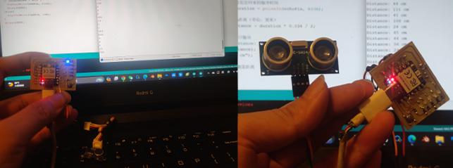
Group Assignment
For this week's assignment, I need to observe digital signals and analog signals separately. In the previous weeks I have learned how to use oscilloscope and multimeter, so this week I decided to measure ultrasonic sensor and analog gray sensor measurement.
Ultrasonic Sensor
          void setup() {
            Serial.begin(9600);
            pinMode(trigPin, OUTPUT);
            pinMode(echoPin, INPUT);
          }

          void loop() {
            digitalWrite(trigPin, LOW);
            delayMicroseconds(2);
            digitalWrite(trigPin, HIGH);
            delayMicroseconds(10);
            digitalWrite(trigPin, LOW);

            long duration = pulseIn(echoPin, HIGH);
            long distance = duration * 0.034 / 2;

            Serial.print("Distance: ");
            Serial.print(distance);
            Serial.println(" cm");
            delay(100);
          }
I observed the waveform signals of the two pins of the ultrasonic sensor: Trig pin and Echo pin.
Echo pin
Trig pin
Analog Gray Sensor
          void setup()
          {
              Serial.begin(9600); // open serial port, set the baud rate to 9600 bps
          }
          void loop()
          {
              int val;
              val=analogRead(0);   //connect grayscale sensor to Analog 0
              Serial.println(val,DEC);//print the value to serial
              delay(100);
          }
Individual Assignments
Input Devices
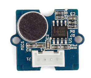
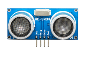
In order to understand how to master the performance of the microcontroller board and the use of sensors for digital signal types, I chose sound sensor and ultrasonic sensor. By using these two sensors, I can just intuitively understand the input of digital signals and analog signals, use the serial port to output the results of sensor measurements on the IDE window, and judge whether the sensor is used correctly according to the state of the data.
Sound Control Light
The sound sensor uses the sound sensor in Grove Beginner kit, which can measure the intensity of sound (range 0-1023) by connecting analog pins. According to the intensity value measured by the sound sensor, it is judged that the sound exceeding a certain threshold controls the state of the LED lamp; secondly, in order to visually see the specific value, I use serial port to print the data directly on the serial port monitor.
          int soundPin = 2; // DIGITAL sound sensor is to be attached to analog
          int ledPin = 0; // Digital LED is to be attached to digital
          void setup() {
            pinMode(ledPin, OUTPUT);
            pinMode(soundPin, INPUT);
            Serial.begin(9600);
          }
          void loop(){
            int soundState = digitalRead(soundPin); // Read sound sensor’s value
            Serial.println(soundState);
            // if the sound sensor’s value is greater than 400, the light will be on.
            //Otherwise, the light will be turned off
            if (soundState == HIGH) {
              digitalWrite(ledPin, HIGH);
              delay(1000);
            }else{
              digitalWrite(ledPin, LOW);
            }
            delay(1000);
          }
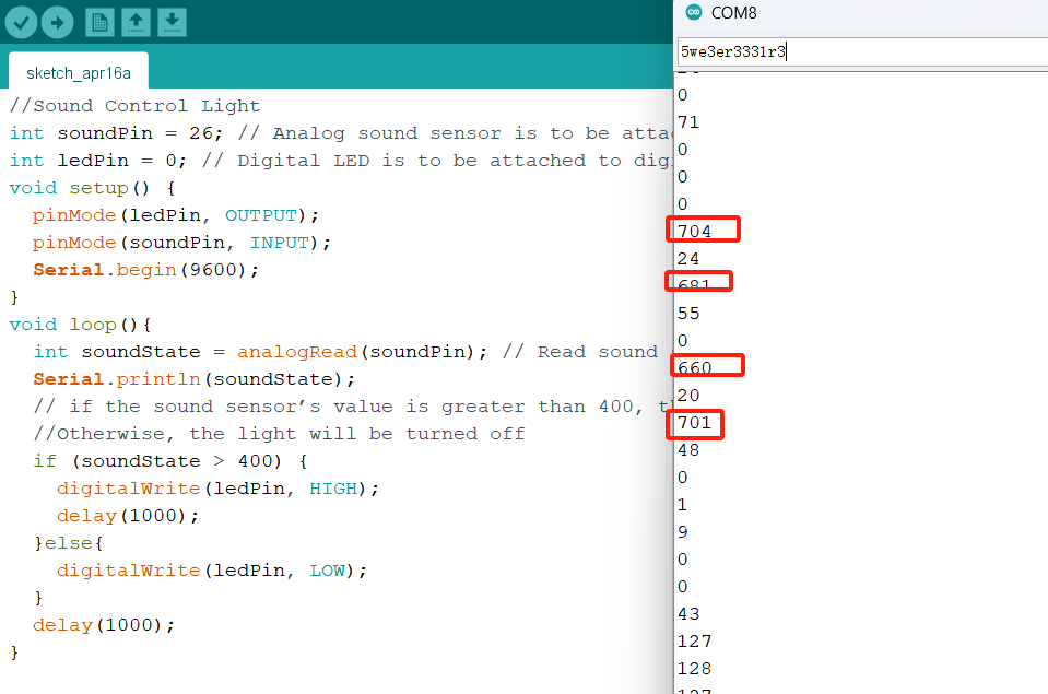
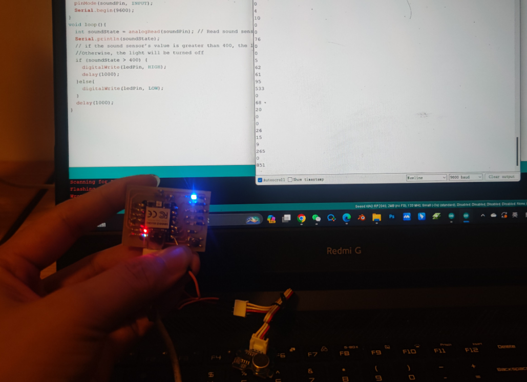
Then, I tried to connect the sound sensor to the digital pin, only to obtain the status of the sensor: By judging the voltage of the sound sensor pin, the LED state is controlled. Therefore, I changed three main things in the code area: 1) changed the read sound sensor pin to a digital pin;2) changed the function of the read pin value to digitalRead (); and 3) changed the judgment condition to whether the sound sensor pin is HIGH. Finally, change the connection on the hardware. specific contents are as follows:
          int soundPin = 2; // sound sensor is to be attached to digital
          int soundState = digitalRead(soundPin); // Read sound sensor’s value
          if (soundState == HIGH)
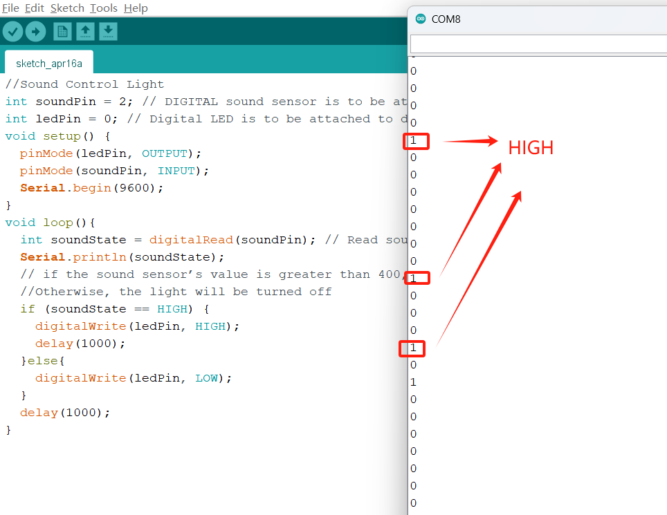
Sound sensor is to change the electrical signal by sensing the sound of the outside world and complete the detection function. It should be noted that the sound sensor can only determine whether there is sound (that is, if it exceeds a certain decibel intensity, it outputs a high level, otherwise it is a low level), and cannot detect the intensity of the sound (specific decibel value). Therefore, in practical applications, it is necessary to determine the type of sensor according to the use scene.
Ultrasonic Sensor
In this case, I chose the ultrasonic sensor (HC-SR04). HC-SR04 ultrasonic sensor is a simple and practical distance measuring sensor with a wide range of distance measuring (2 cm to 4 m), high accuracy (up to several mm), non-contact distance measuring and simple to use. It works by sending ultrasonic pulses, receiving reflected signals and measuring the time difference, using the speed of sound waves propagating in the air to calculate the distance from the target object to the sensor.
The first step was to connect the ultrasonic sensor to my development board. HC-SR04 ultrasonic sensor has four pins, namely VCC,GND,Trig,Echo. VCC and GND are connected to 3.3v and GND pins respectively, Trig,Echo are connected to digital pins respectively, such as D1, D2.
            // Import the required libraries
            #include

            // Define pins for ultrasonic sensors
            const int trigPin = 2; // Trig pin connected to D2 of BOARD
            const int echoPin = 1; // Echo pin connected to D1 of BOARD

            void setup() {
                // Initialize serial communication
                Serial.begin(9600);
                // Set the ultrasonic sensor pins to input or output
                pinMode(trigPin, OUTPUT);
                pinMode(echoPin, INPUT);
            }

            void loop() {
                // Send a short pulse to the Trig pin to trigger ultrasonic ranging
                digitalWrite(trigPin, LOW);
                delayMicroseconds(2);
                digitalWrite(trigPin, HIGH);
                delayMicroseconds(10);
                digitalWrite(trigPin, LOW);

                // Read the pulse time sent back by the ultrasonic sensor
                unsigned long duration = pulseIn(echoPin, HIGH);

                // Convert pulse time to distance in centimeters
                unsigned int distance = duration * 0.034 / 2;

                // Output distance data through serial port
                Serial.print("Distance: ");
                Serial.print(distance);
                Serial.println(" cm");

                // Wait a while and measure the distance again.
                delay(1000);
            }
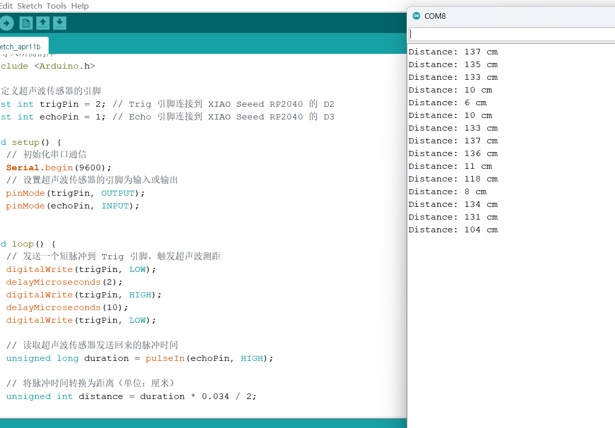
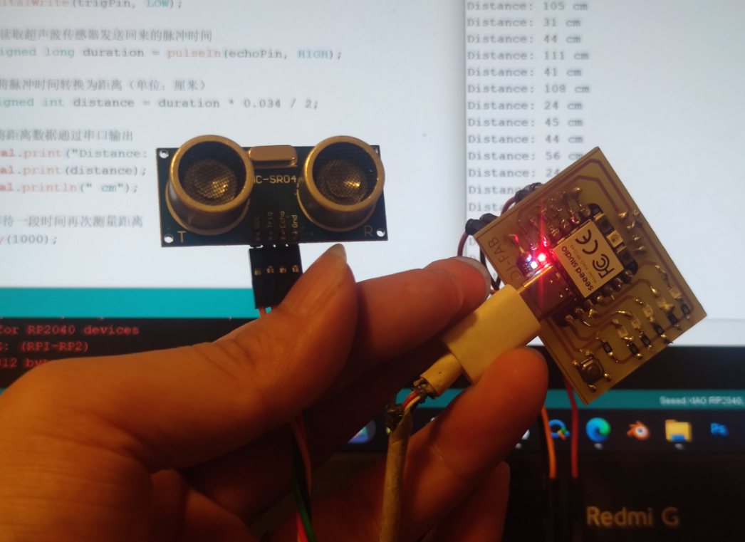
Ultrasonic ranging sensor is realized by using the principle of ultrasonic wave, which calculates the time of transmitting and receiving sound waves by calculating the module, and calculates the distance by using the propagation speed of sound. Ultrasonic sensors can be used to produce devices that sense distance from objects, but the range is limited.