Week10. Mechanical Design,Machine Design
Assignments
- Group assignment:
- design a machine that includes mechanism+actuation+automation+application
- build the mechanical parts and operate it manually
- document the group project and your individual contribution
Hero Shot
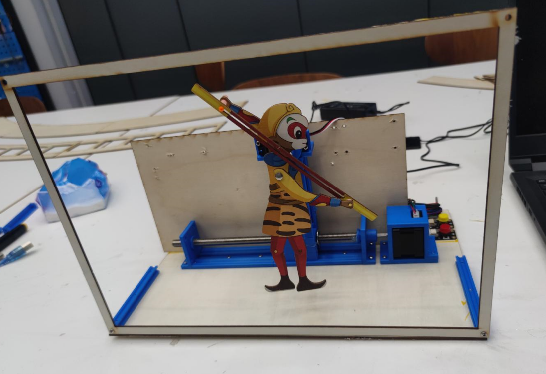
Group Assignment
Idea
Shadow play is a traditional Chinese folk art with a history of thousands of years. It has become an non marerial cultural heritage with its unique performance mode and cultural connotation. Shadow play performances rely on elaborate shadow figures, made of cow or donkey hide, carved and colored, with flexible joints. During the performance, shadow puppets are projected onto the white curtain by lighting behind it. Artists use poles and clues to manipulate shadow figures, with music and lyrics, to interpret vivid stories. Shadow play combines literature, music, painting, sculpture and other artistic elements.
The charm of shadow puppetry lies not only in the craftsmanship of its figures, the performance methods, and the rich stories, but also in its role as a means of cultural transmission. However, traditional shadow puppetry often requires people to work behind the screen, which limits its dissemination. Therefore, I began to think that if shadow play could be performed using mechanized methods.

Sketch
I tried to combine the structure and working mode of traditional shadow play to design the appearance of the whole system. For ease of presentation, it was designed to be a monolithic structure where people could see people moving in front of the device as if they were watching television. I designed the following first edition styles.
Modeling
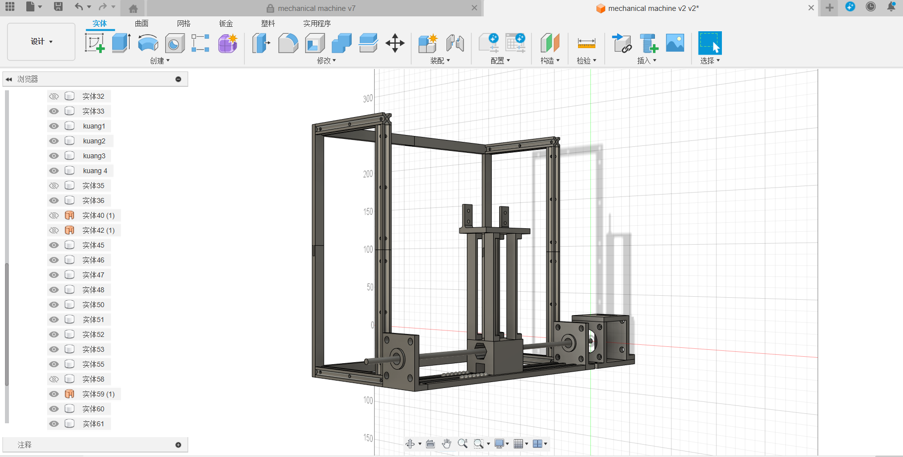
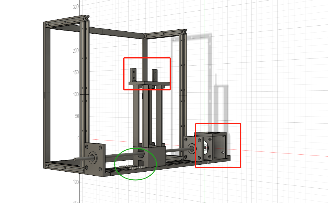
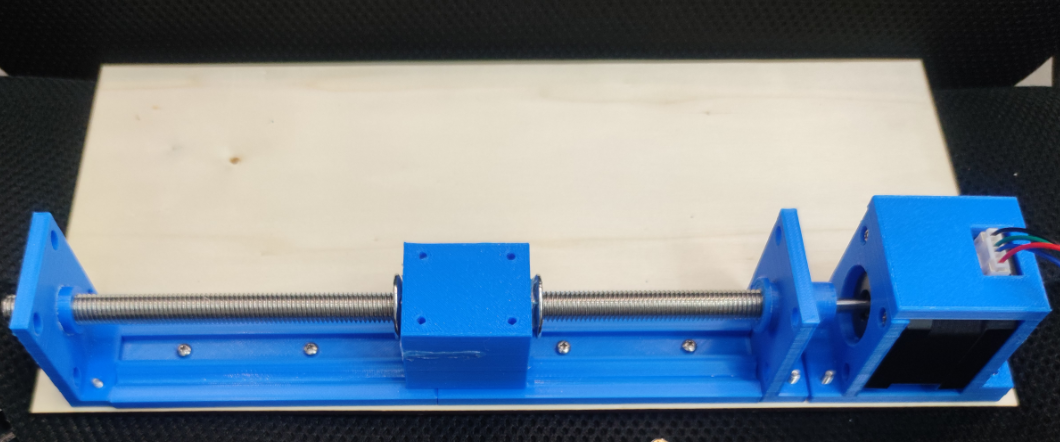
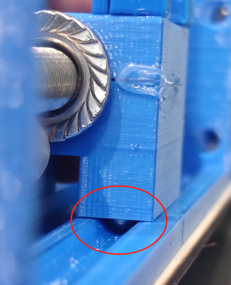
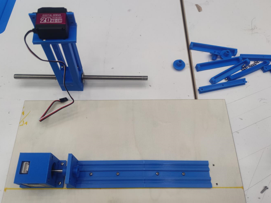
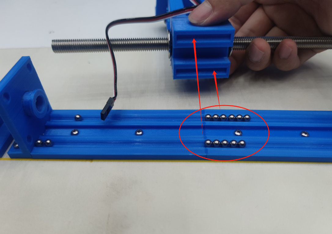
I tried using fusion360 to create a model of the entire system. First, I created the framework of the whole system and identified three key problems: 1. the position of the stepper motor and how to provide power for lateral movement;2. the position of the steering gear and how to control the shadow task movement; and 3. using steel balls as part of the slide to solve the movement problem.To verify this, I printed out a few parts and assembled them to see if they slid smoothly.
Electronics System
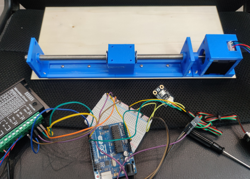
The whole electronic system I used Arduino control board, buttons, stepper motors, drivers and digital steering gear and other components. In order to ensure the smooth operation of the system, first of all, I try to write a program to control the rotation of the digital steering gear; secondly, according to the parameters of the driver and the stepping motor, write a program to control the stepping motor to do periodic reciprocating motion. In this process, the stepper motor heating serious, through consulting the data manual, found that the current mode does not match, due to high current, resulting in excessive motor load.
Secondly, the preset function goal of the system is to use the keys as switches to control the operation of the whole system. However, in the actual test process, the function of key detection in the code is in the cycle process, due to the long execution time of the stepping motor in the code execution process, when the key is pressed, it is found that the key is in a failure state. After several attempts, it was found that it was necessary to set the key detection to interrupt detection, so as to detect the key state at any time and control the system operation.
The following shows the completed system code:
          #include

            Servo myServo;      // Create a servo object

            // Define stepper motor pins
            const int stepPin = 5;
            const int dirPin = 6;
            const int buttonPin1 = 2; // Button pin for controlling the stepper motor

            // Define servo motor pin
            const int servoPin = 13;   // Define servo control pin
            const int buttonPin2 = 3; // Button pin for controlling the servo

            volatile bool motorRunning = false; // Flag variable to record the working status of the stepper motor
            volatile bool servoRunning = false; // Flag variable to record the working status of the servo
            unsigned long lastInterruptTime1 = 0; // Last interrupt time for the stepper motor
            unsigned long lastInterruptTime2 = 0; // Last interrupt time for the servo

            unsigned long lastMotorStepTime = 0; // Last stepping time of the stepper motor
            unsigned long lastServoMoveTime = 0; // Last movement time of the servo
            int motorStepCount = 0; // Step counter for the stepper motor
            int servoAngle = 0; // Servo angle
            bool motorDirection = true; // Flag variable to record the direction of the stepper motor

            const int motorStepInterval = 200; // Step interval of the stepper motor (microseconds)
            const int servoMoveInterval = 20; // Movement interval of the servo (milliseconds)
            const int motorSteps = 20000; // Number of steps per run
            const int maxServoAngle = 60; // Maximum angle of the servo
            const int servoSpeedFactor = 1; // Factor to adjust the speed of the servo movement, the larger the value, the slower the speed

            void setup() {
              // Initialize the serial port for debugging
              Serial.begin(9600);

              // Initialize stepper motor pins
              pinMode(stepPin, OUTPUT);
              pinMode(dirPin, OUTPUT);
              pinMode(buttonPin1, INPUT_PULLUP); // Use internal pull-up resistor

              // Initialize servo
              myServo.attach(servoPin);
              pinMode(buttonPin2, INPUT_PULLUP); // Use internal pull-up resistor

              // Attach interrupts to buttonPin1 and buttonPin2
              attachInterrupt(digitalPinToInterrupt(buttonPin1), toggleMotor, FALLING);
              attachInterrupt(digitalPinToInterrupt(buttonPin2), toggleServo, FALLING);

              Serial.println("Setup complete");
            }

            void loop() {
              unsigned long currentTime = millis();
              if (motorRunning && (currentTime - lastMotorStepTime >= motorStepInterval / 1000)) {
                runMotor(currentTime);
              }
              if (servoRunning && (currentTime - lastServoMoveTime >= servoMoveInterval * servoSpeedFactor)) {
                runServo(currentTime);
              }
            }

            // Stepper motor control function
            void runMotor(unsigned long currentTime) {
              if (motorStepCount < motorSteps) {
                digitalWrite(stepPin, HIGH);
                delayMicroseconds(100);
                digitalWrite(stepPin, LOW);
                lastMotorStepTime = currentTime;
                motorStepCount++;
              } else {
                motorStepCount = 0;
                motorDirection = !motorDirection; // Toggle direction
                digitalWrite(dirPin, motorDirection ? HIGH : LOW);
                Serial.print("Motor direction: ");
                Serial.println(motorDirection ? "Forward" : "Backward");
              }
            }

            // Servo control function
            void runServo(unsigned long currentTime) {
              static bool increasing = true; // Record the movement direction of the servo

              if (increasing) {
                servoAngle++;
                if (servoAngle >= maxServoAngle) {
                  increasing = false;
                }
              } else {
                servoAngle--;
                if (servoAngle <= 0) {
                  increasing = true;
                }
              }

              myServo.write(servoAngle);
              Serial.println(servoAngle);
              lastServoMoveTime = currentTime;
            }

            // Stepper motor interrupt service routine
            void toggleMotor() {
              unsigned long interruptTime = millis();
              if (interruptTime - lastInterruptTime1 > 200) { // Simple debounce processing
                motorRunning = !motorRunning;
                motorStepCount = 0;
                Serial.print("Motor running: ");
                Serial.println(motorRunning);
                lastInterruptTime1 = interruptTime;
              }
            }

            // Servo interrupt service routine
            void toggleServo() {
              unsigned long interruptTime = millis();
              if (interruptTime - lastInterruptTime2 > 200) { // Simple debounce processing
                servoRunning = !servoRunning;
                Serial.print("Servo running: ");
                Serial.println(servoRunning);
                lastInterruptTime2 = interruptTime;
              }
            }

Mechanical System
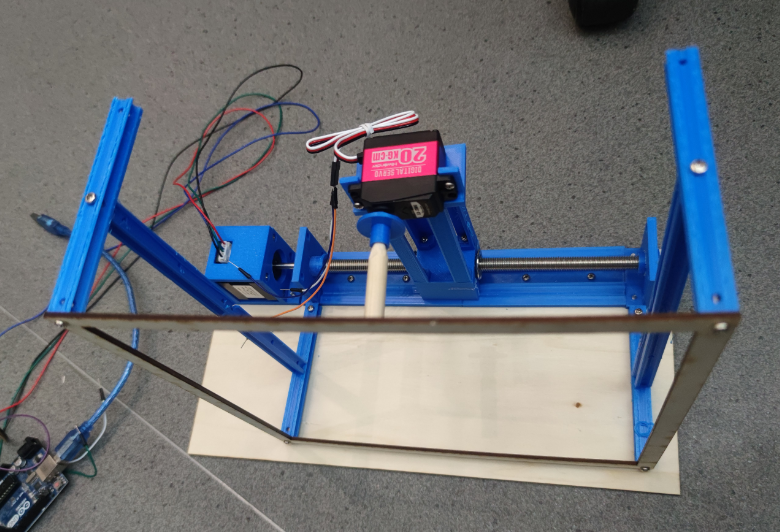
Use a 3D printer to print out the required parts. In the factor of time, cut the frame of the whole screen using a laser cutter. Assemble the system using screws and nuts.

Testing
Controller and Actuator
- Arduino uno
- Button*2
- Digital Servo
- Stepping Motor
Process
- 3D Printing: Print the sliding rail, servo support and mounting bracket, and stepper motor mount
- Laser Cutting: Cut the machine base plate, demonstration frame, and demonstration puppet
In this week's project, I attempted to design a machine that can automatically demonstrate shadow puppetry. After inputting the program, pressing the corresponding button will complete different actions. In the demonstration video below, you can see that the entire system includes a 3D-printed structure, a cut wood structure, and an electronic control system. The digital servo is connected to the puppet's control axis, allowing the puppet to perform simple actions through the servo's rotation. The stepper motor controls the puppet's movement direction, enabling horizontal left and right movements. Ideally, the puppet can complete hand movements while moving left and right. In this demonstration, two buttons can separately control the hand and leg movements. The servo controls the puppet's central axis rotation to perform the action of waving a weapon, while the stepper motor controls the legs for left and right movement.
Conclusion
In this project design, the biggest problem encountered is how to use the buttons to control the stepper motor and the steering gear separately, and the two do not interfere with each other. These questions require that the control code of the stepper motor and the steering gear cannot be simply combined together, but needs to be implemented in a manner similar to multithreading, so that the two are independent of each other. In order to achieve the design effect, I have made two improvements: first, the key uses interrupt detection, which can detect and judge during the operation of the motor (or steering gear), and execute the command; secondly, the time slice method (by searching Internet information and AI) is used, so that the steering gear and the stepping motor can work at the same time.
            attachInterrupt(digitalPinToInterrupt(buttonPin1), toggleMotor, FALLING);
            attachInterrupt(digitalPinToInterrupt(buttonPin2), toggleServo, FALLING);
            unsigned long currentTime = millis();
            if (motorRunning && (currentTime - lastMotorStepTime >= motorStepInterval / 1000)) {
              runMotor(currentTime);
            }
            if (servoRunning && (currentTime - lastServoMoveTime >= servoMoveInterval * servoSpeedFactor)) {
              runServo(currentTime);
            }
Of course, other problems were encountered during production, such as rapid heating of the stepper motor, which was caused by an error in setting the current gear switch, or a large noise of the stepper motor, which was due to the excessive time set for motor rotation. But, eventually, for version 1.0 of this project, in the plan, I wanted to introduce the Y-axis to change the movement space of the character, and design more character movements, through the rotation of the steering gear or motor, so that the character could tell a smooth story.