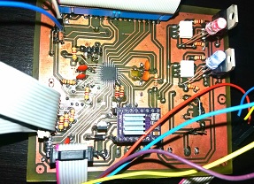
Development of custom electronic boards with CNC Router.
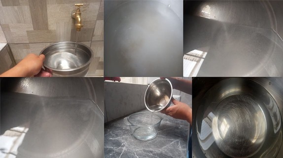
In the city of Pillco Marca, the water supply has notable impurities when collected from the tap, especially during and after maintenance and treatment periods in the reservoirs. The water supplied can arrive dirty and cloudy, forcing residents to let the water run until it is cleaned. Additionally, when collecting water, it is common to have to let it sit so that it settles a whitish color, which raises serious concerns about its quality and safety for human consumption.
Pillco Marca is a community that depends on the water supply from local reservoirs. These reservoirs require periodic maintenance and treatment to ensure water quality. However, during these periods, water quality is compromised, resulting in cloudy and dirty water. This problem is not new and has been a recurring concern for residents. In the past, recommendations such as boiling water before consumption have been implemented, but these measures have not been completely effective in ensuring water purity.
Impurities in water can include chemical contaminants, bacteria, and other microorganisms that can cause illness when ingested. Residents should let the water run until the water clears as it is cloudy. This negatively impacts the health and well-being of communities that rely on this water supply, increasing the risk of gastrointestinal illnesses and other long-term health complications. Therefore, the perception that tap water is unsafe generates distrust in the local water supply system.
Improve the quality of the water supply in the city of Pillco Marca, with the implementation of a control and monitoring system and thus ensure that the water is safe and clean for human consumption at all times.
This project is closely related to Sustainable Development Goal number 6, which seeks to guarantee the availability and sustainable management of water and sanitation for all. By addressing the quality of water supply and promoting safe drinking practices, the project directly contributes to achieving this goal. By improving access to clean, safe water, the risk of water-related diseases can be significantly reduced and the quality of life of affected communities improved. Furthermore, by promoting sustainable water management practices, the project also contributes to the conservation and protection of water resources for future generations.

The lack of an adequate filtration system in the home contributes to the persistence of this problem. Consequently, I propose the development of a project that comprehensively addresses the improvement of water supply in homes. This project will seek to design, implement and test an accessible and effective filtration system that can be adopted by me and then transferred to the inhabitants of the city.
By facing this challenge, I not only aspire to improve water quality in Pillcomarca, but also to empower the community with a practical and sustainable solution. Participation in Fabacademy will provide the tools and knowledge necessary to carry out this project effectively, leveraging innovation and technology for the benefit of the community.
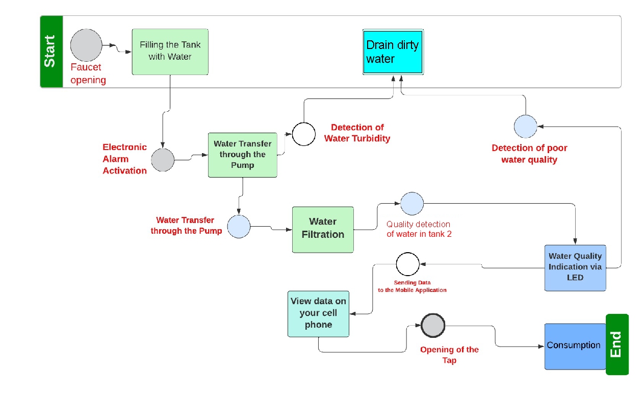
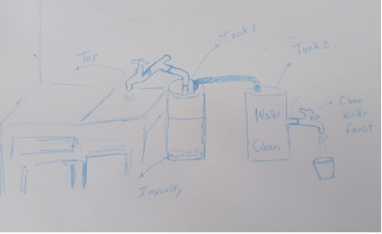
In summary, the problem that I will address is a challenge that I face with great joy and desire to contribute to my city. With this project I want to provide families with quality water free of impurities and my goal is to design and implement a domestic filtration system. that improves the quality of water and, therefore, the quality of life of the residents of this city, the process of which I mention below.

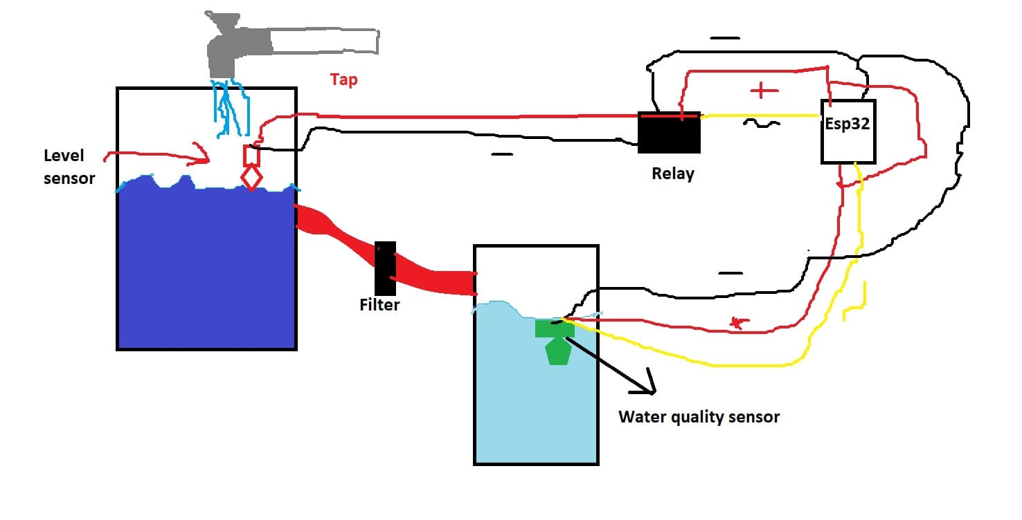
The management of this process will be in charge of a level sensor that will automatically control the opening and closing of the tap, ensuring an effective sedimentation cycle. In addition, pH and water quality sensors will be integrated to evaluate the purity and chemical characteristics of the liquid.
Subsequently, through a pumping system, the treated water will be directed to a second tank, specifically intended for home consumption. This tank will also be equipped with a level sensor and a water quality sensor to ensure the safety and drinkability of the supply.
Real-time data collection will be possible thanks to a central electronic circuit, which will be connected via Wi-Fi. The data collected by the water level and quality sensors will be continuously transmitted to a mobile device, allowing constant monitoring and facilitating informed decision-making about water consumption at home.
This holistic approach will not only provide a reliable supply of clean water, but will also offer an intuitive and accessible user interface to monitor and control parameters in real time, providing a complete and technologically advanced solution for efficient water resource management in the domestic environment.
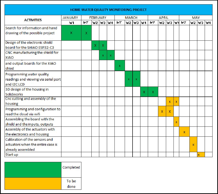
The following image shows in detail the schedule of activities of the final project, where the tasks, their start and end dates, as well as those responsible for each activity are specified.
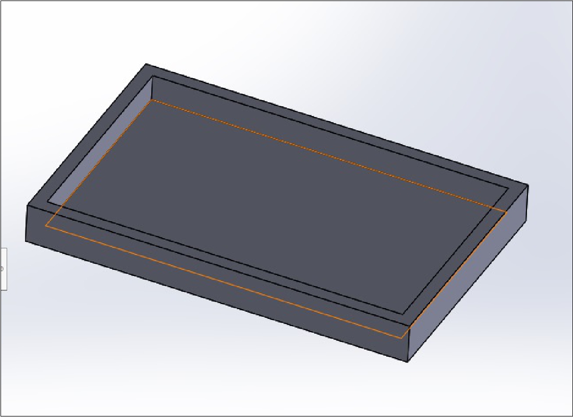
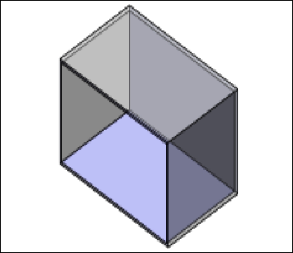
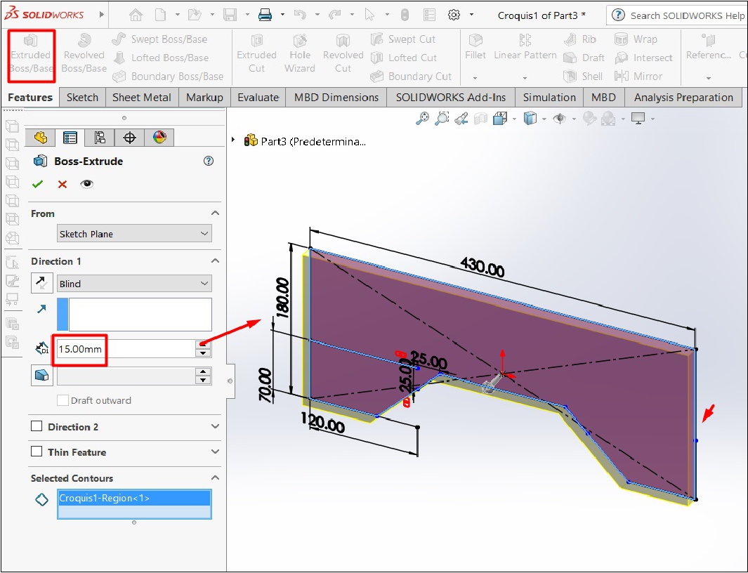
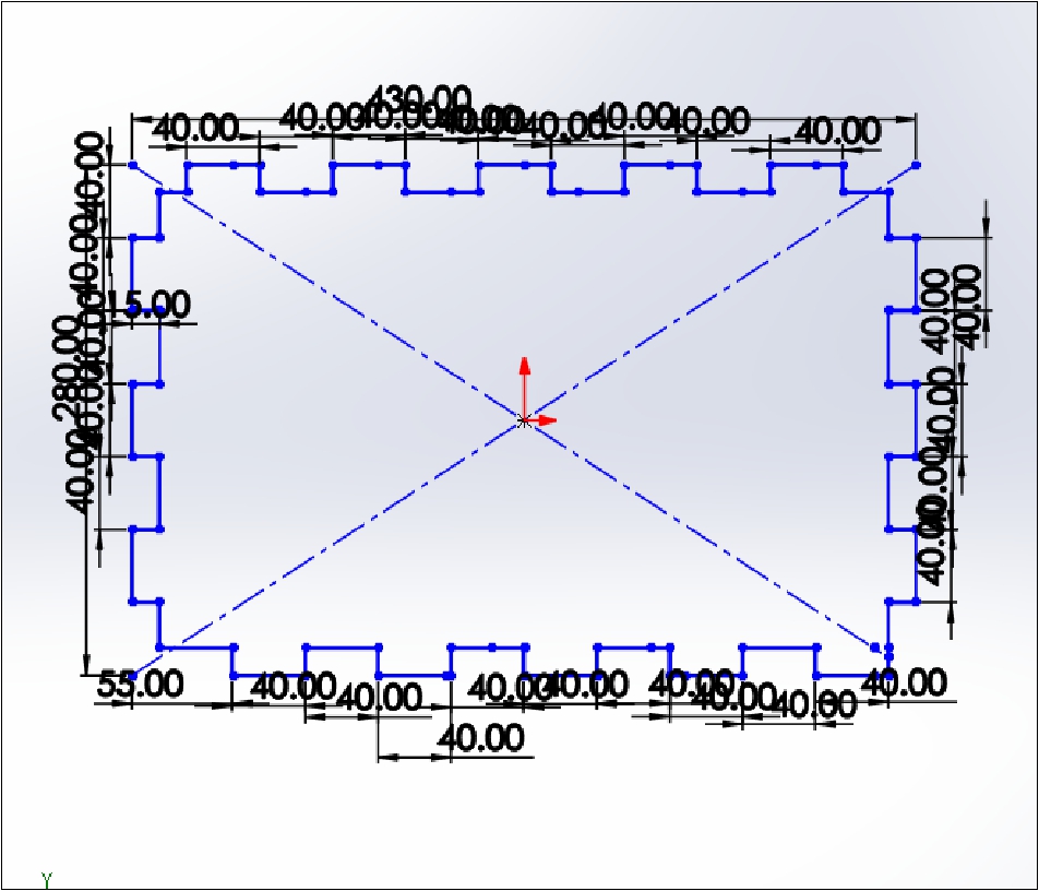
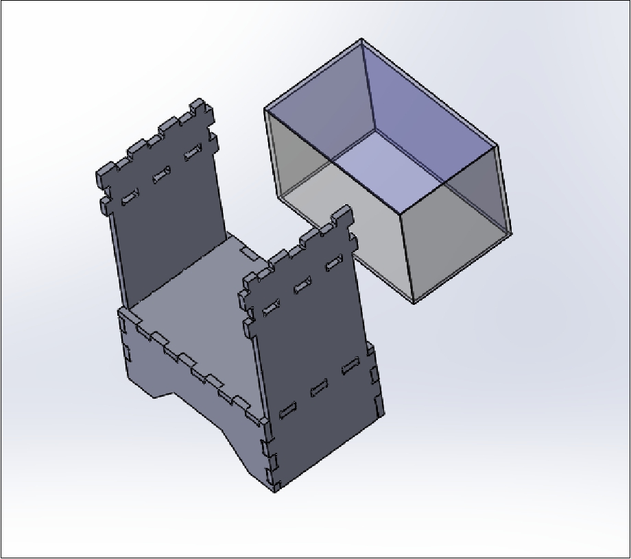
During the last few days, my attention has been completely focused on the meticulous design of the essential elements for the completion of my project: the case and the glass in the SolidWorks software since it is an important part because it will be the visual part of the project.
A glass tank or container was considered to be able to contrast whether the parameters that I see on the cell phones or application are true or not, and the measurements come below.
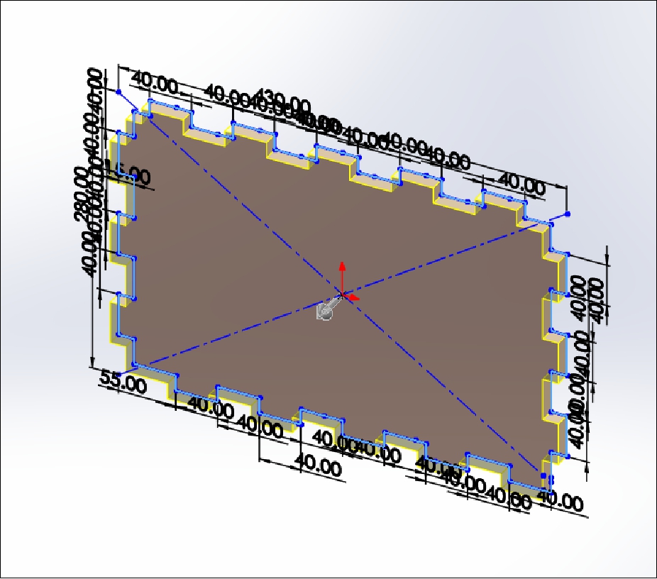
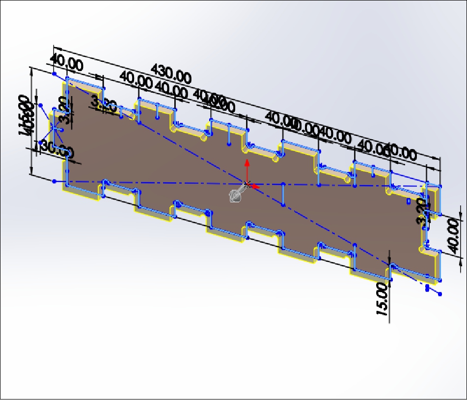
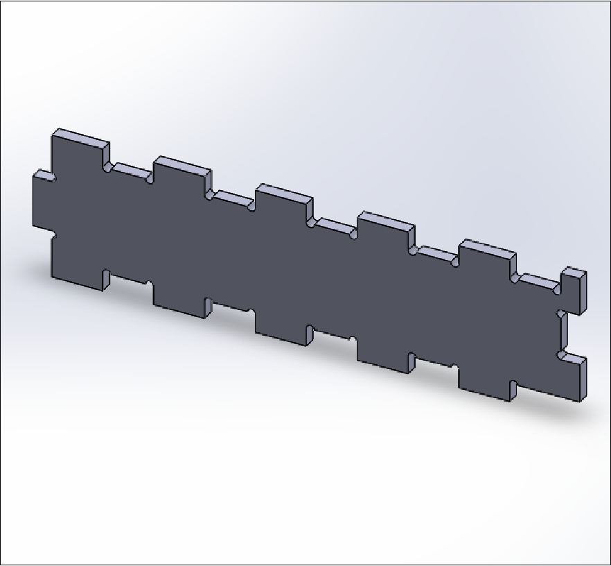
These pieces are the supports of the project, which will be built with OSB material.
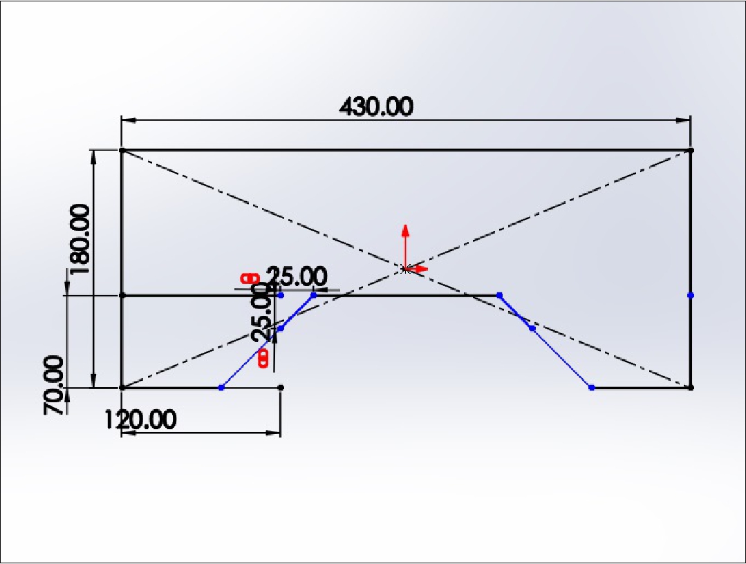
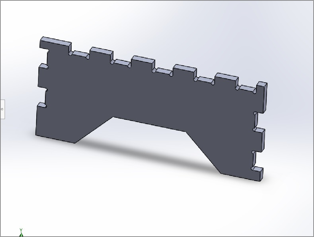
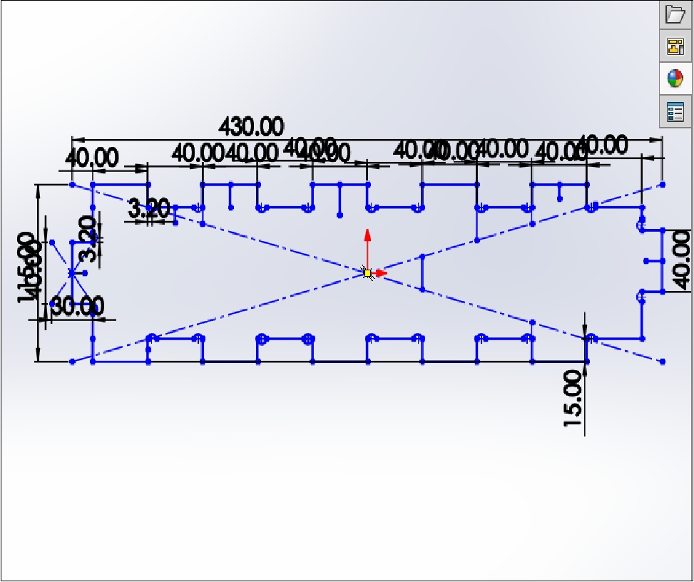
The third piece corresponds to the side supports of the project, which are also made of 15 mm thick OSB.
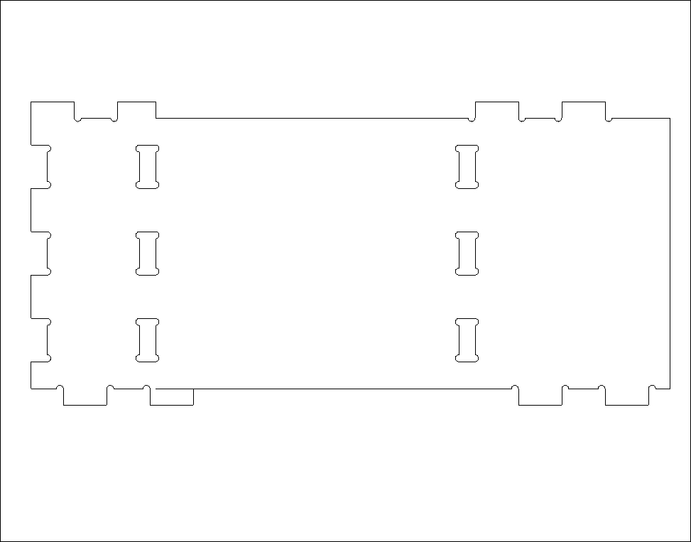
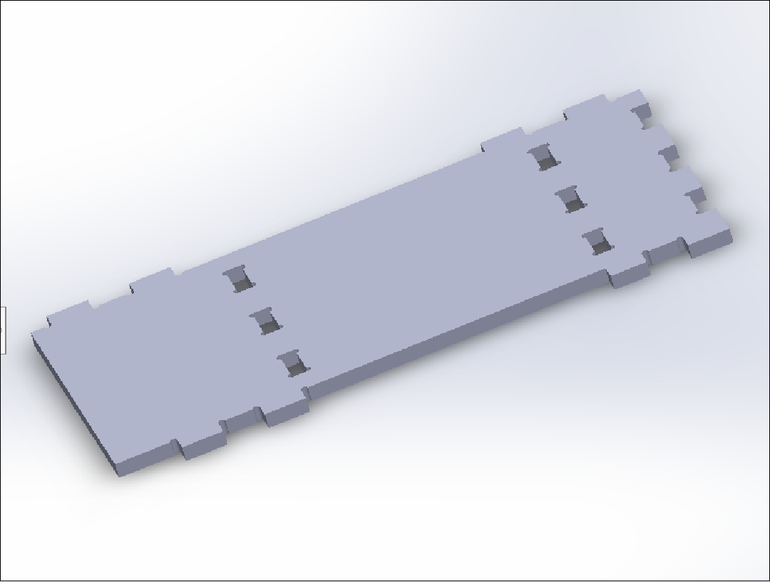
The fourth piece is the platform or table on which the container with water will be placed, which will also be made of 15 mm thick OSB. It is also the top cover of the project
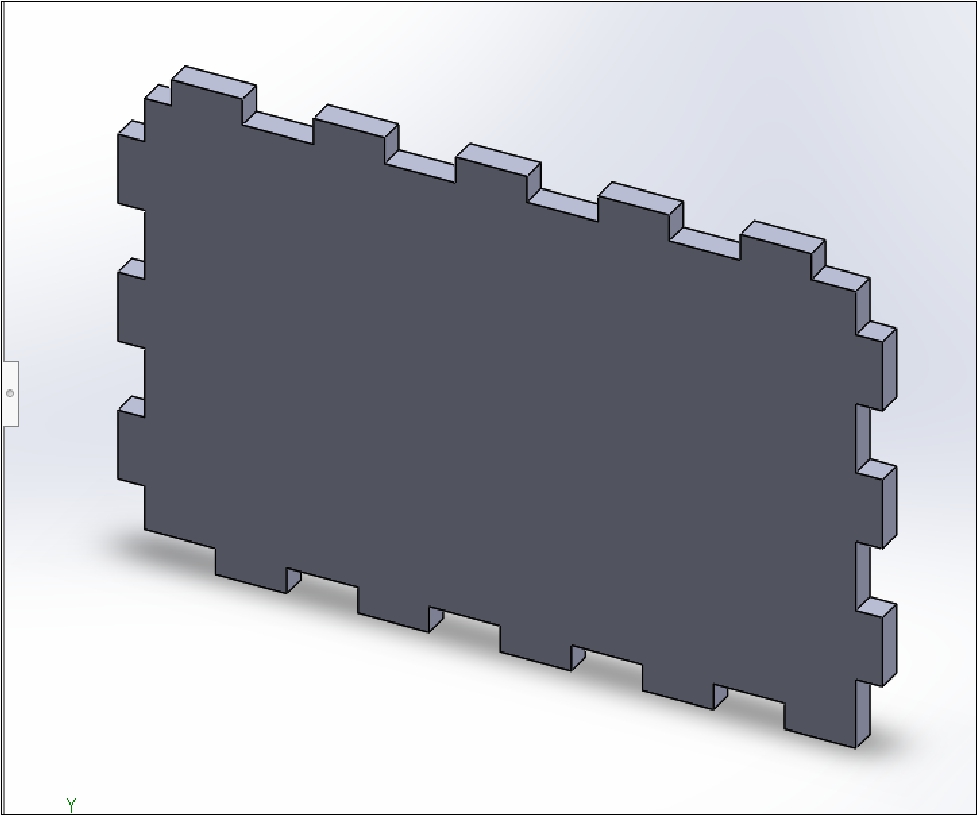
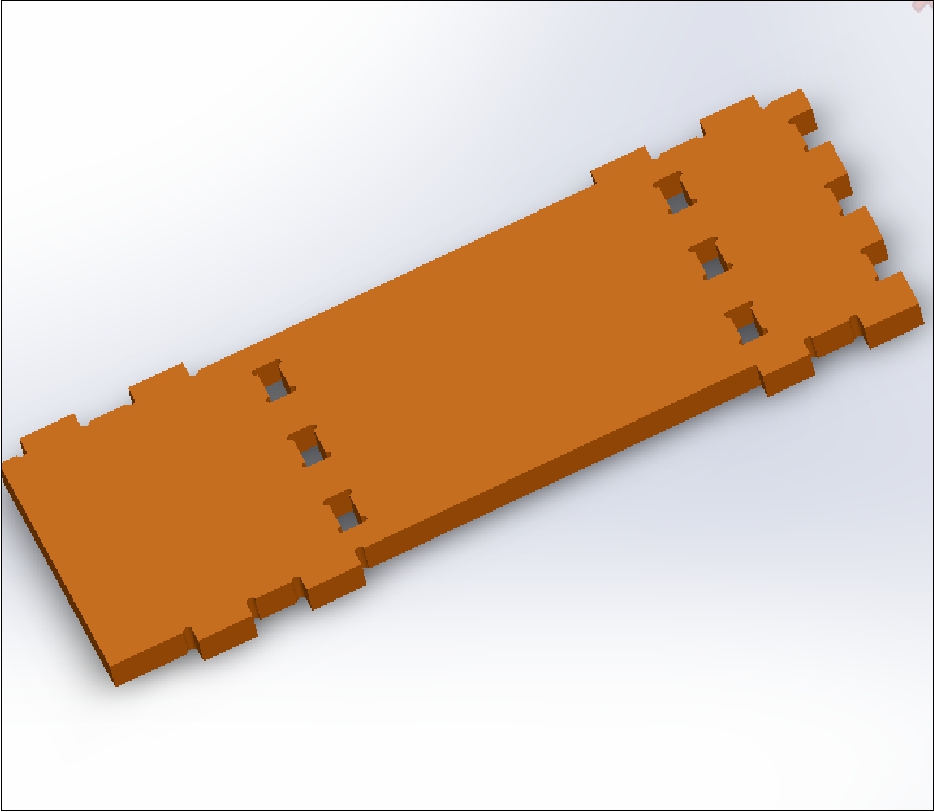
The fifth piece acts as a support and cover for the electronic part that will be placed on top.
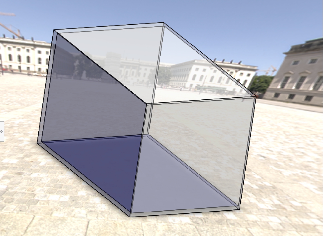
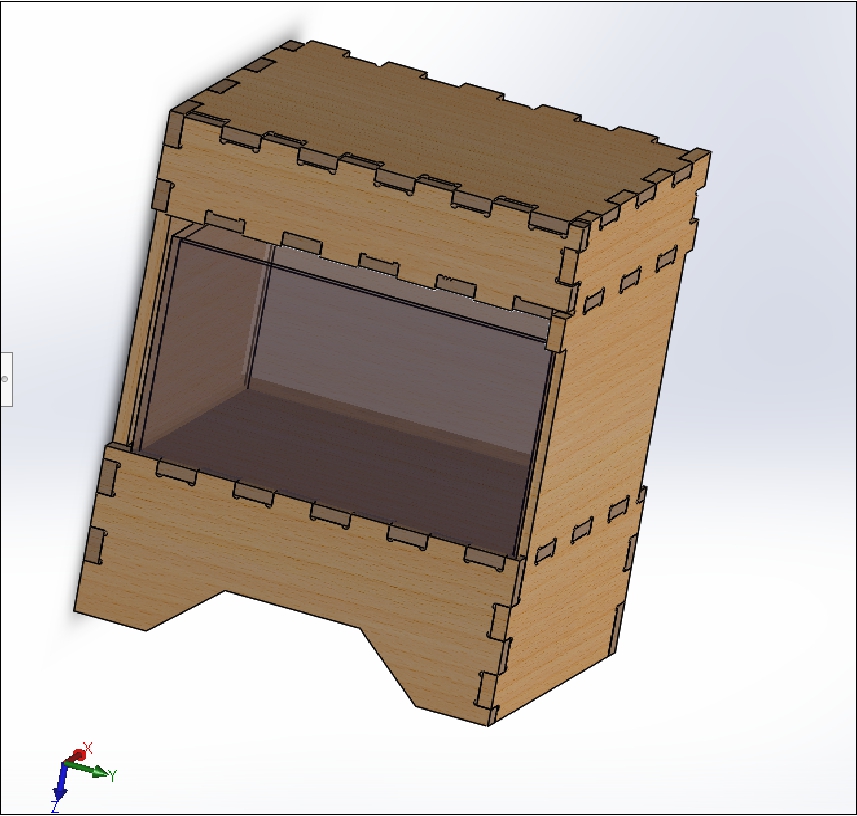
This image illustrates part of the final appearance of the 3D project designed in the software SolidWorks.
The electronic design was carried out using KiCad software. The first step was to make a list of all the necessary components. Then, the electrical schematic was designed and the layout of the components on the schematic diagram was organized meticulously.
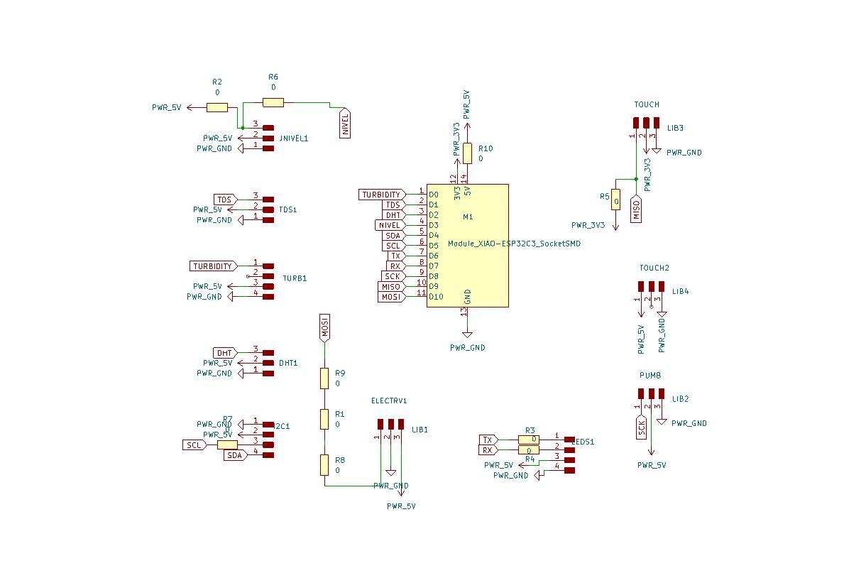
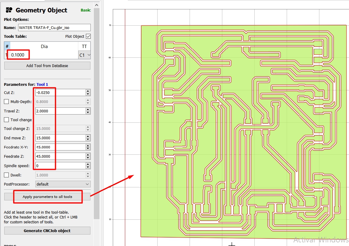
For PCB design, it is important to consider the layout of components in terms of distance and orientation. Additionally, it is crucial to determine the width of the tracks; in my case the width used is 0.8 to 1 mm.
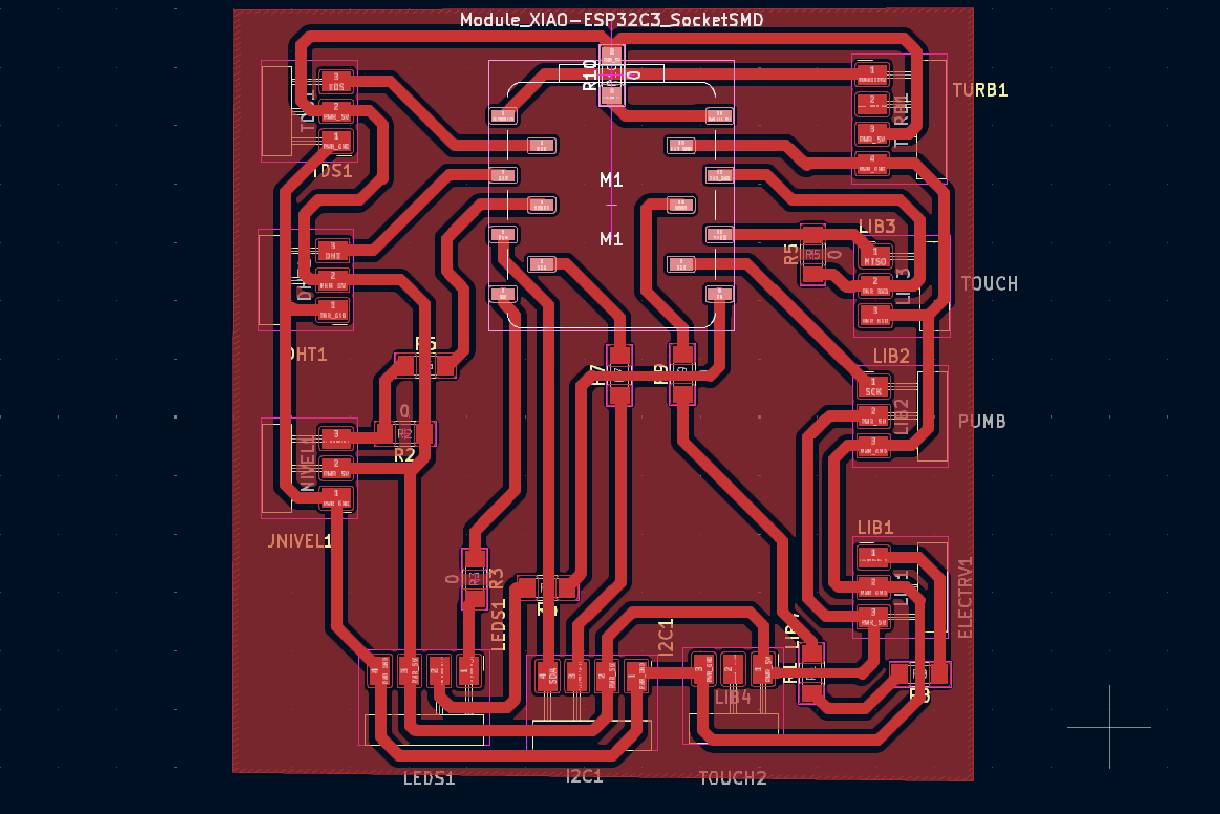
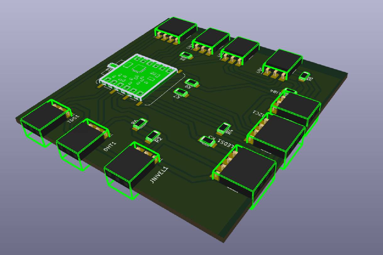
In this process, it is possible to visualize how our board will look in reality, since it is designed on a real scale. Additionally, a 3D view of the board can be generated to obtain a more detailed representation of the final design.
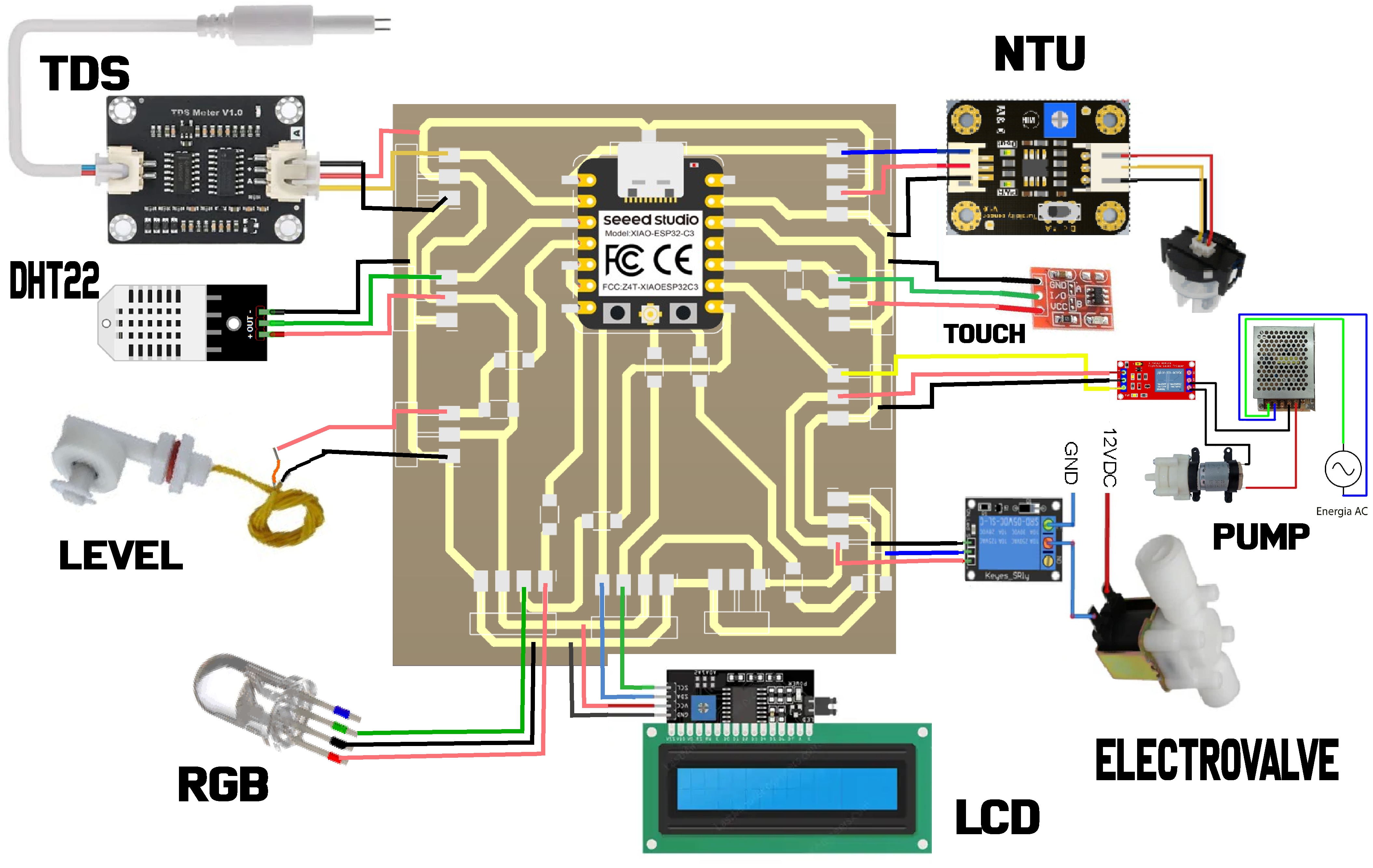
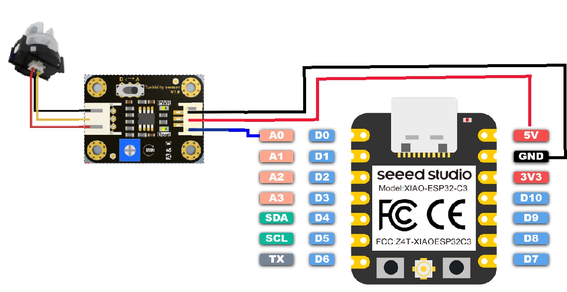
In the following image you can see a better distribution of components for this design and thus have a clearer vision of what our board will be like, with the inclusion of sensors (TDS, turbidity, level, DHT22, capacitive touch) integrated into the board, as well as the actuators, such as the solenoid valve and the mini peristaltic pump, as well as the relay modules.
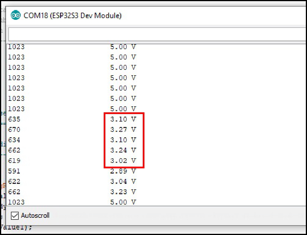
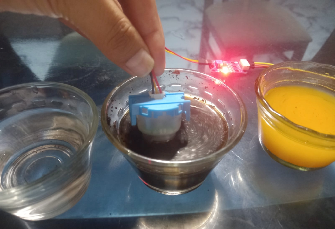
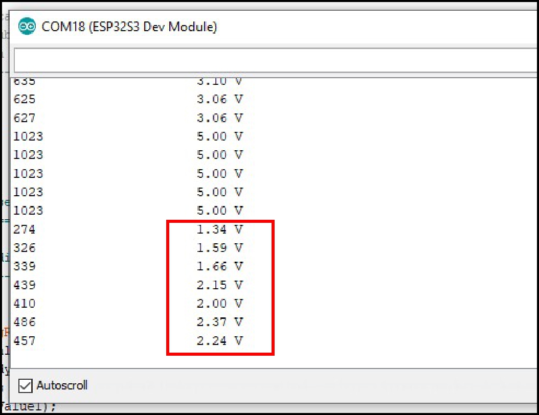
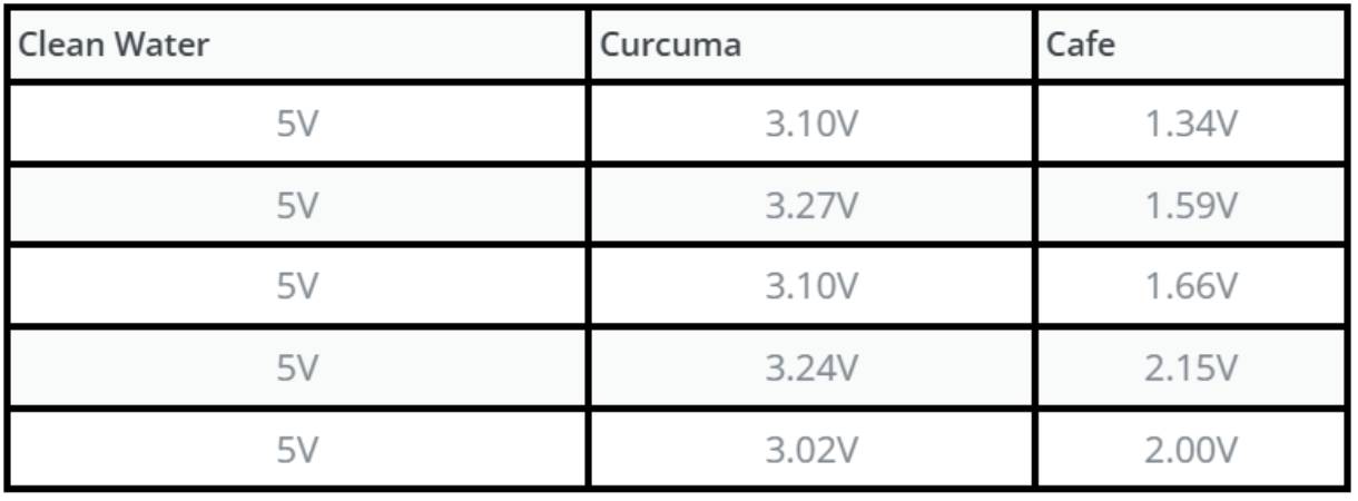
For communication via Serial, I used the turbidity sensor, which will be evaluated with different types of water during the tests.
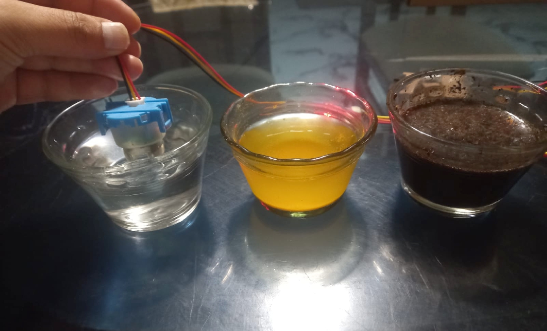
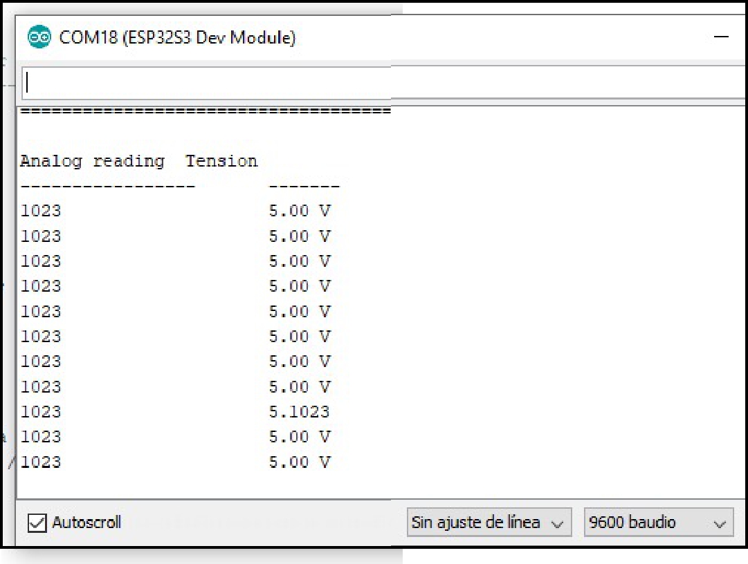
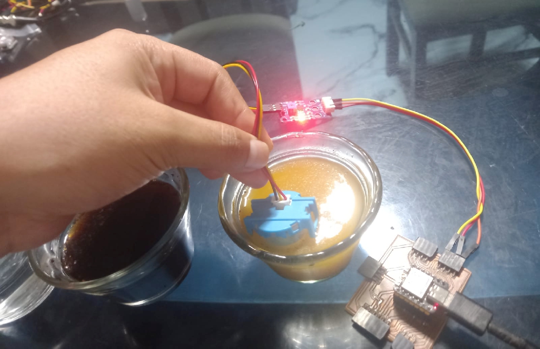
Test with different types of water using serial connection, which is detailed below.
The following images show the testing process carried out with different types of water.
The cutting of the parts that will make up the casing of the first prototype will be carried out with a 4-axis CNC Router 1313 with a rotating device. This process will be carried out at the facilities of the National University Hermilio Valdizán, currently known as Fablab Unheval.
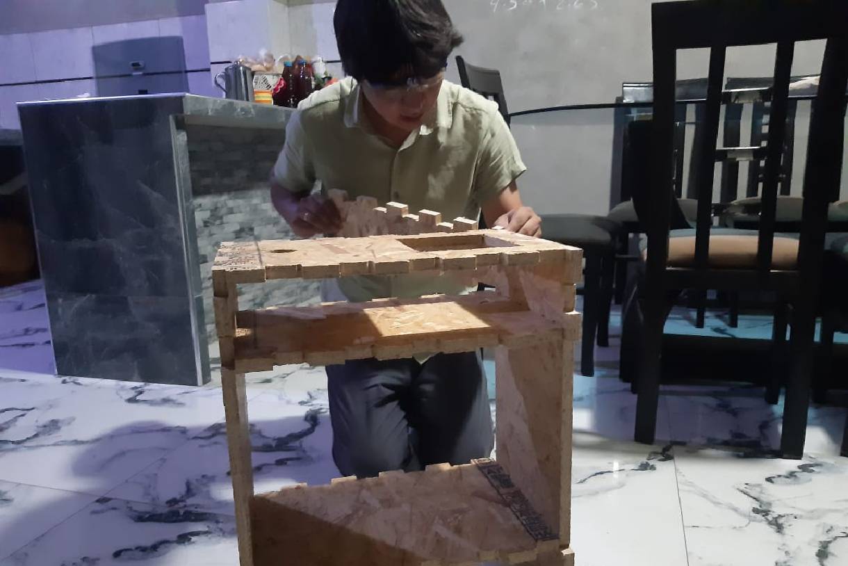
In the process, you can see the parts that will support the project. The center supports were pressed into the side supports. There are three central supports of the same size: two of them have holes and one has none. The support with one hole is placed in the center, the support with two holes is placed on top, and the support without holes is placed at the bottom, the latter being the one that will support the weight of the glass pond with water.
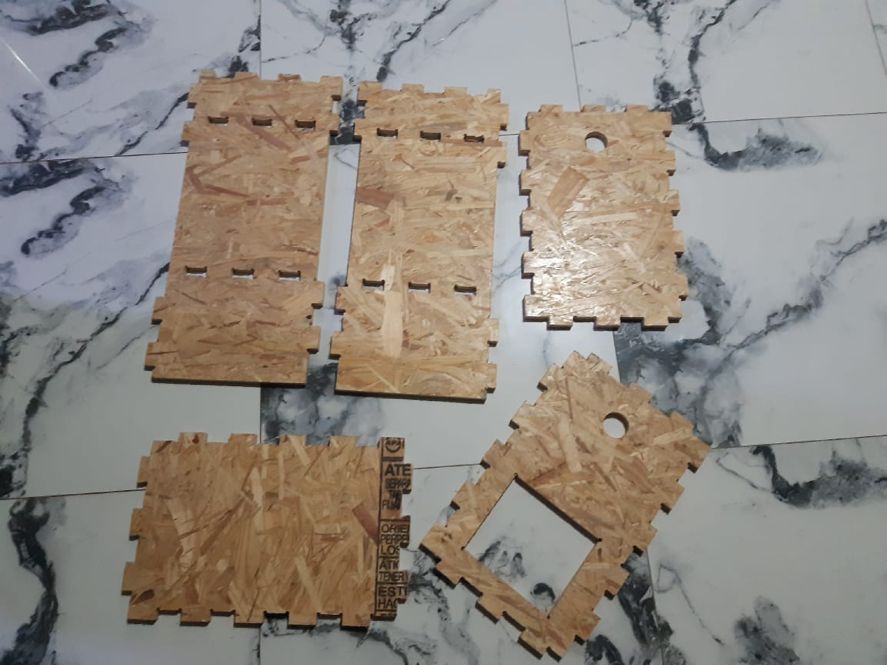
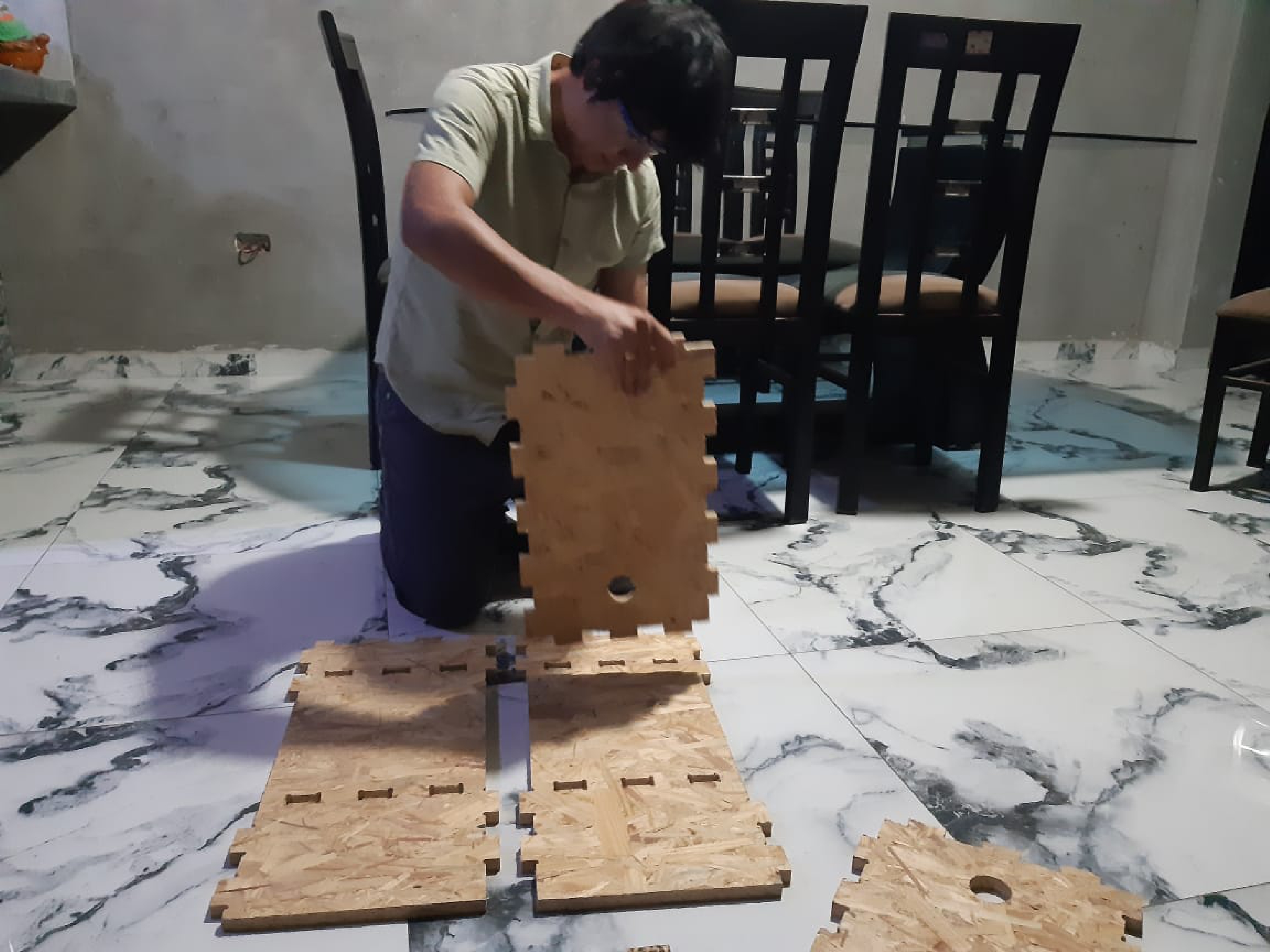
The following images show the placement of the internal supports of the project according to the order mentioned above.
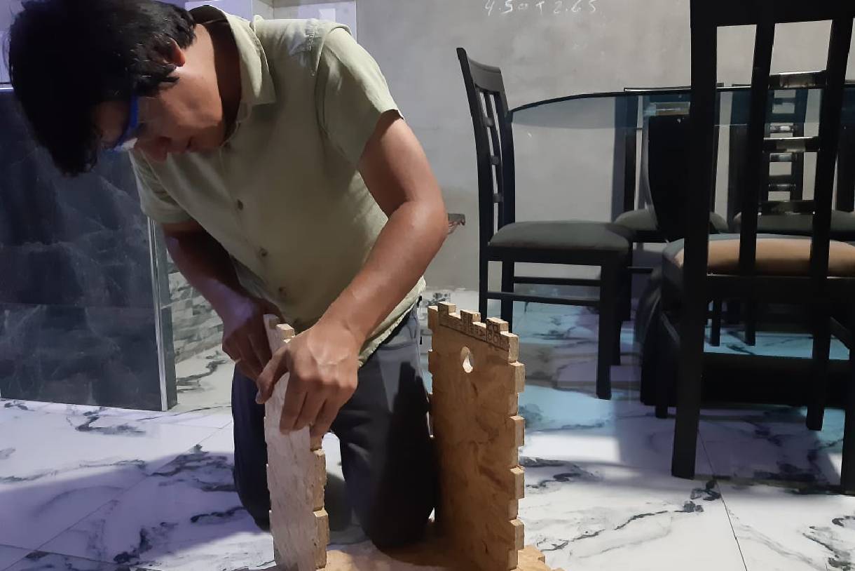
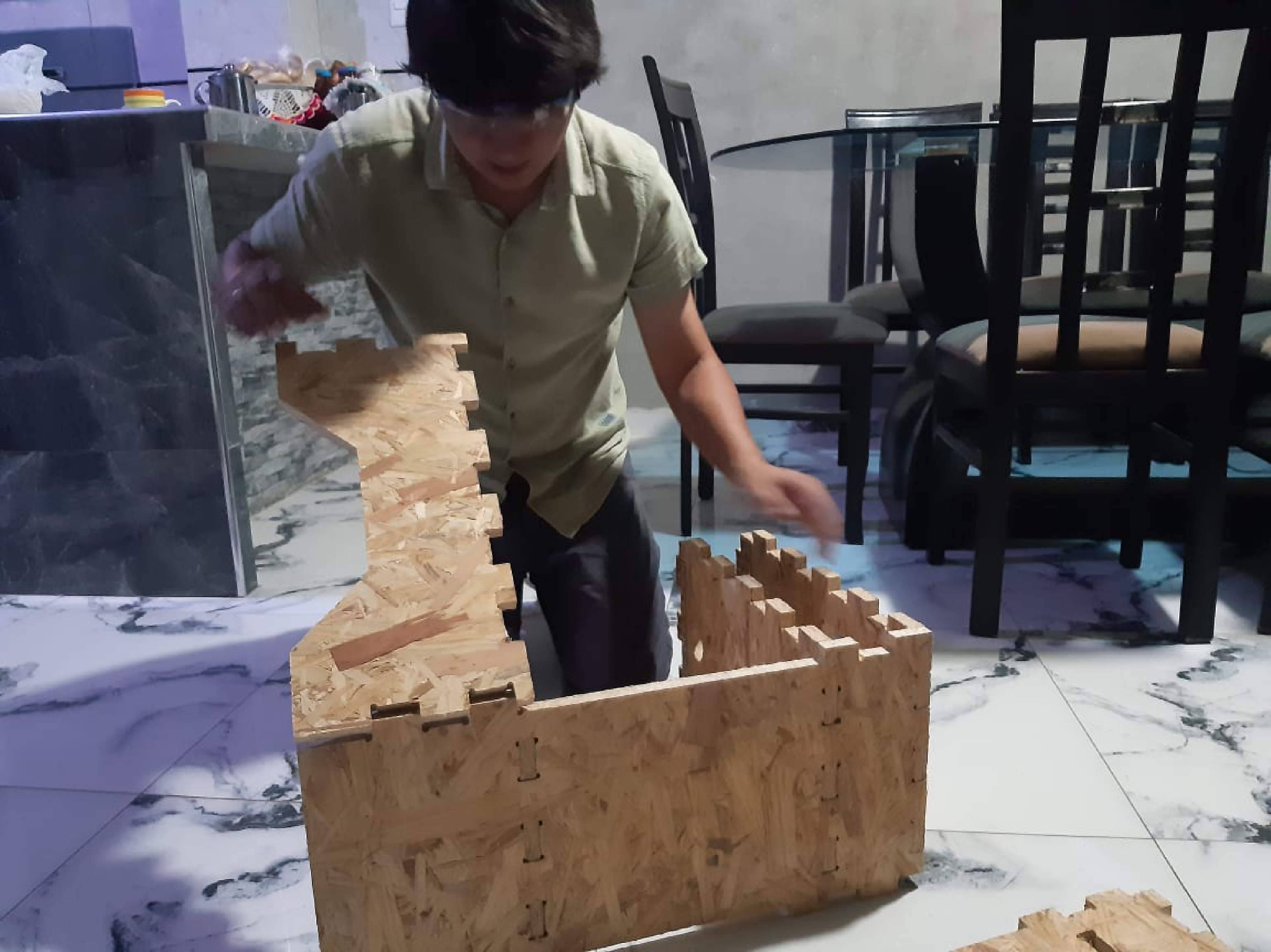
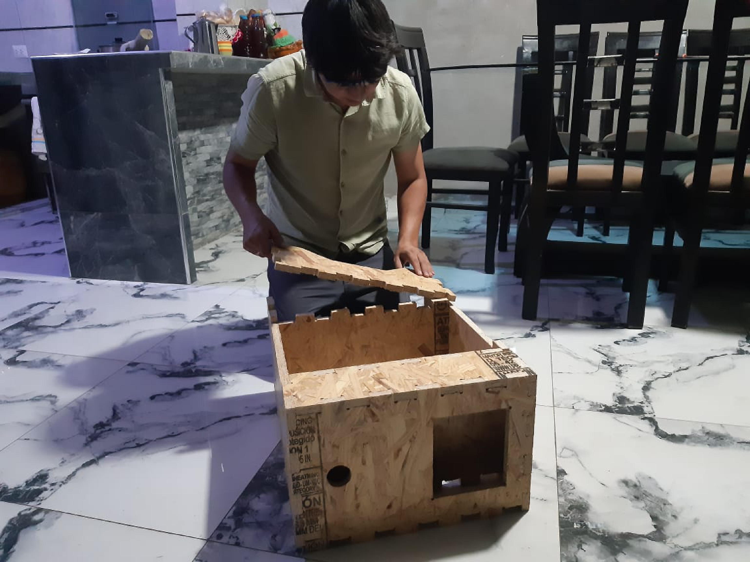
The following image shows the placement of the side and top supports, almost forming a box that will contain the electronic part.
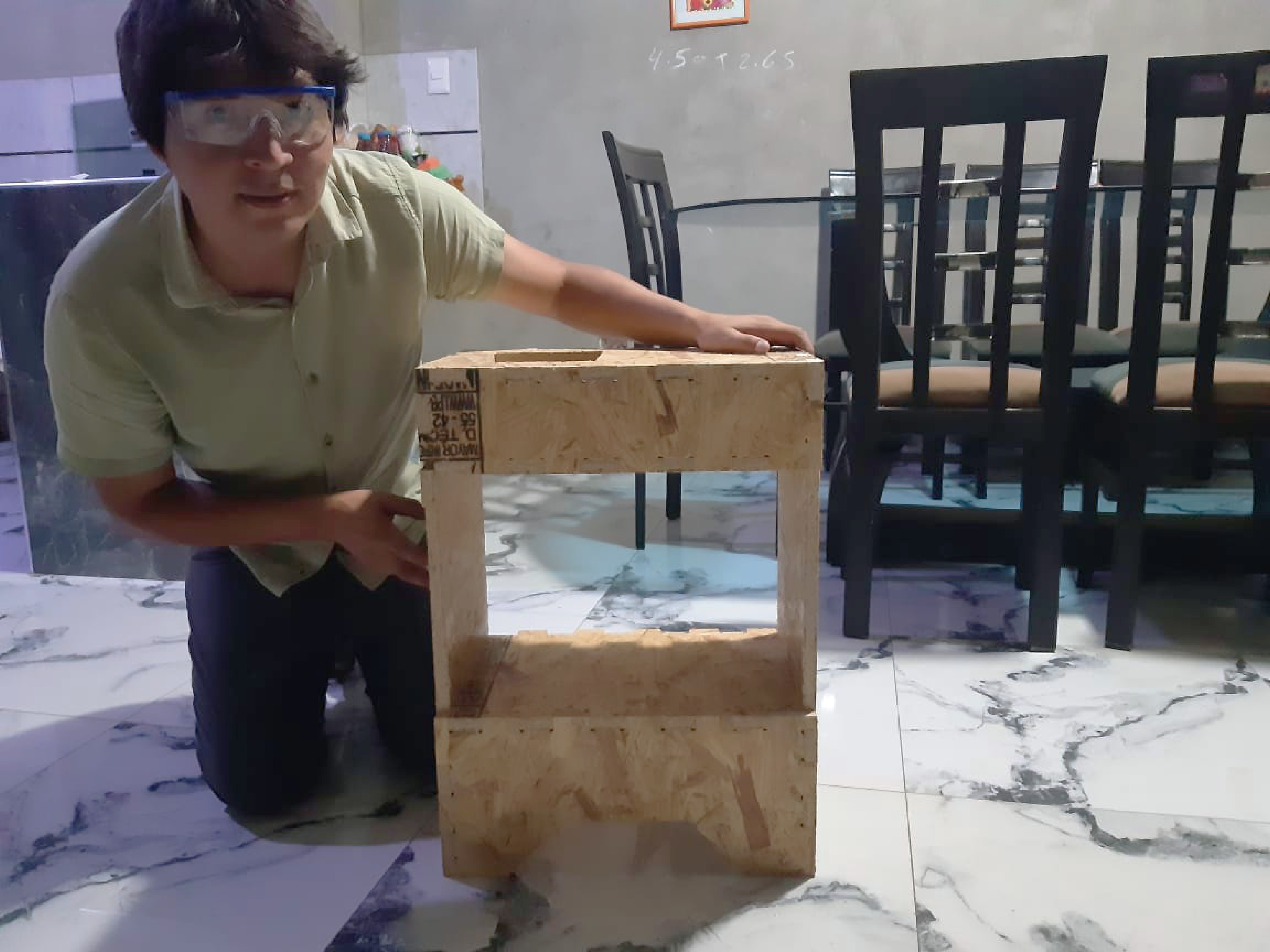
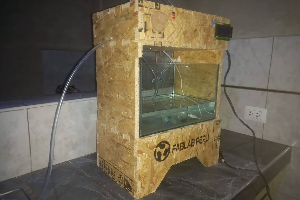
In the following image you can see the assembled casing of the project. A support still needs to be placed that is in the process of being laser machined, including the engraving of the Fablab Perú logo.
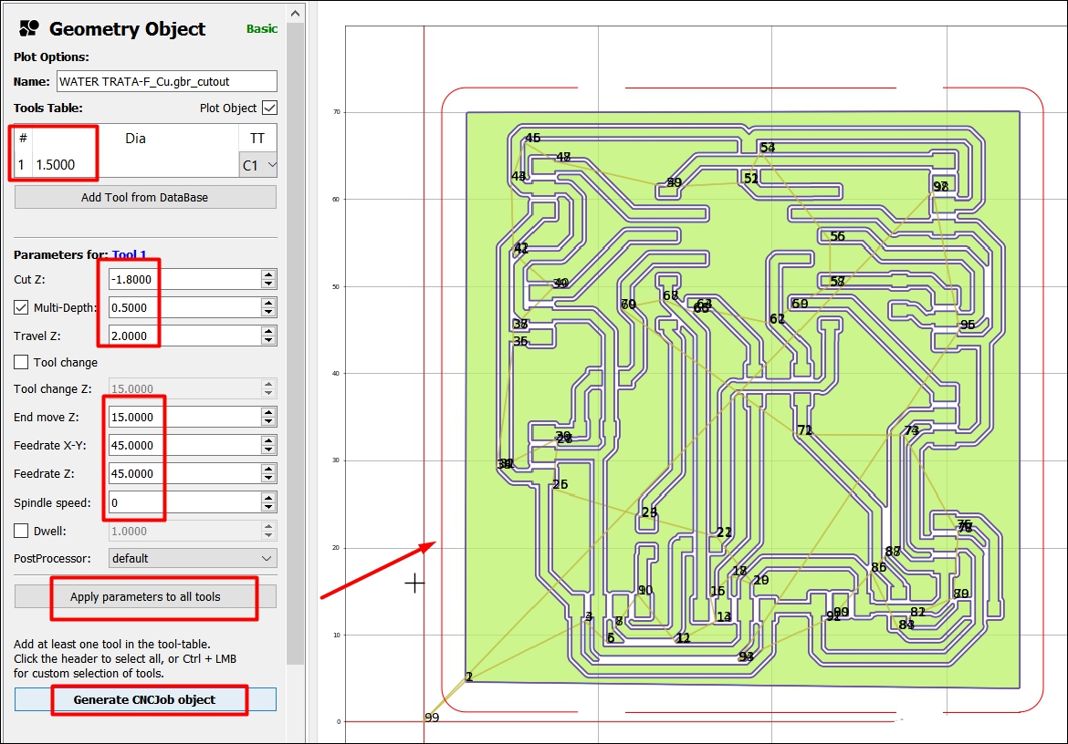
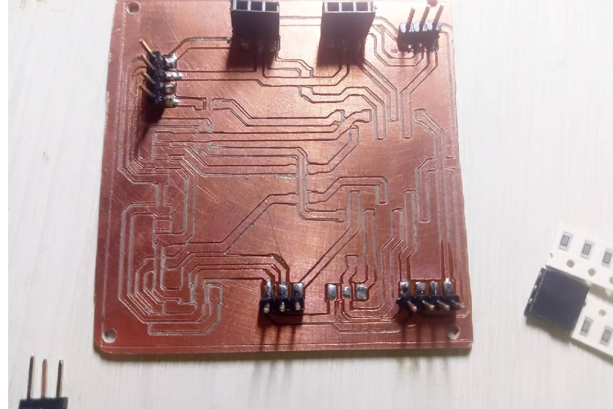
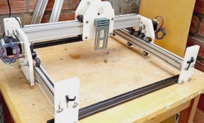
For electronic production, I used the CNC Router machine I built at home, previously featured in Mechanical Design week. Later, I will detail the process step by step.
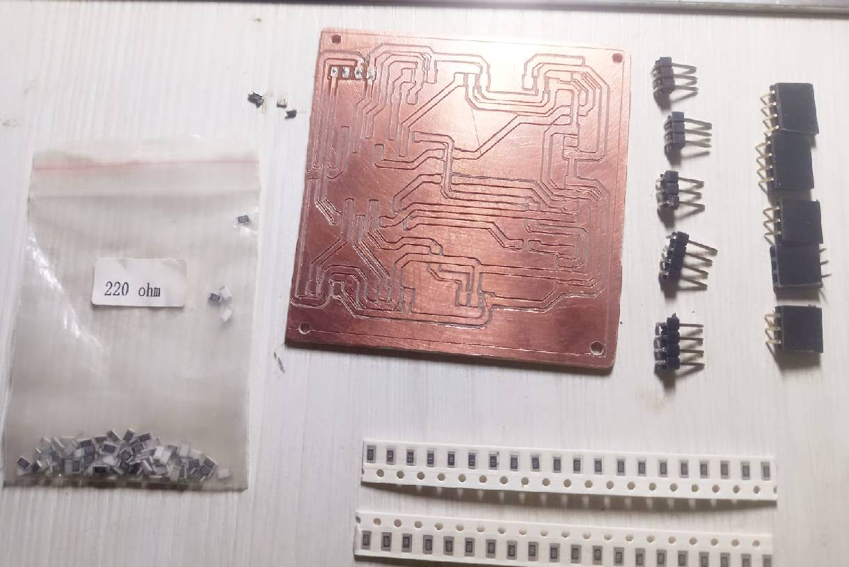
In the following image you can see the components to be used and the first soldered header connectors.
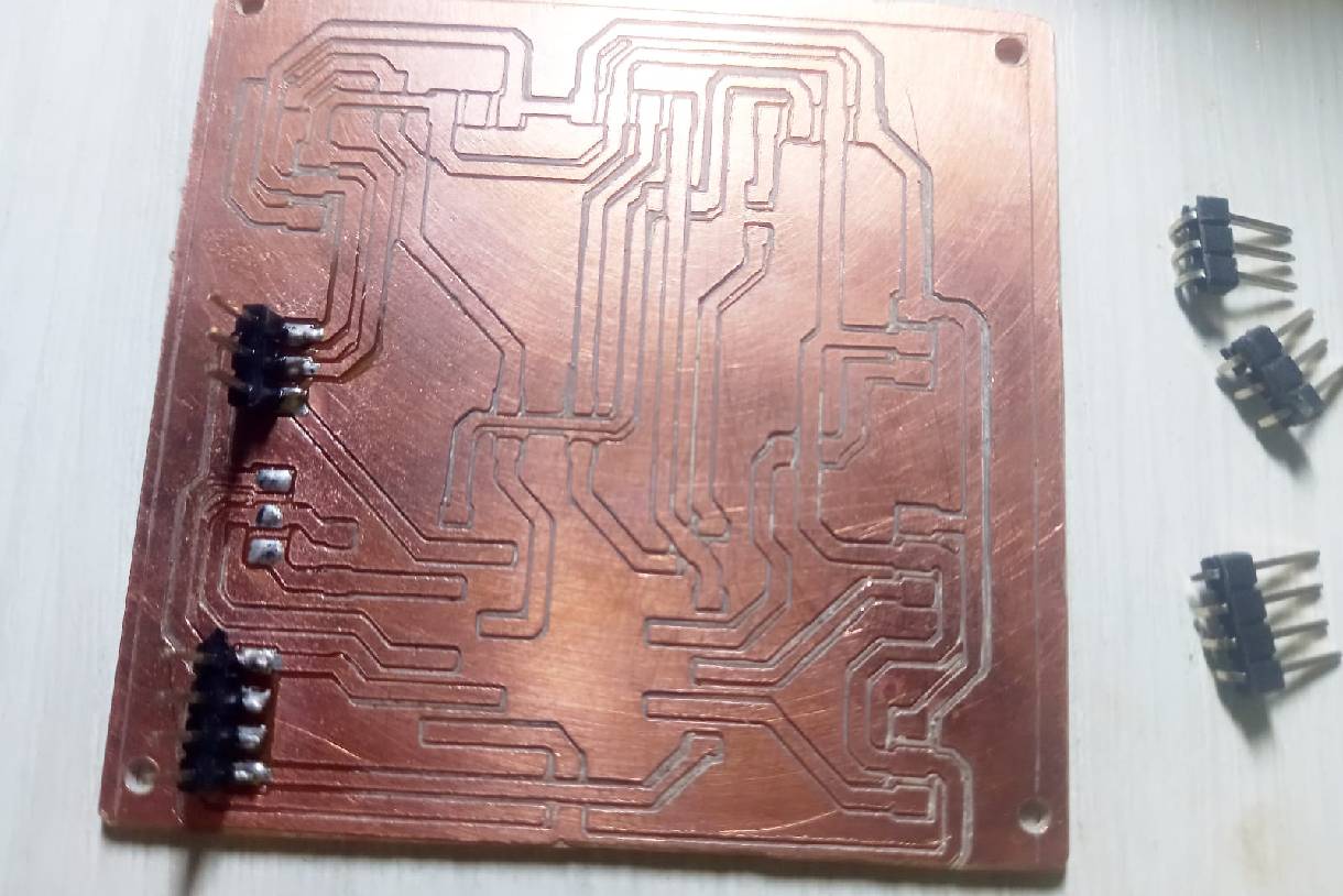
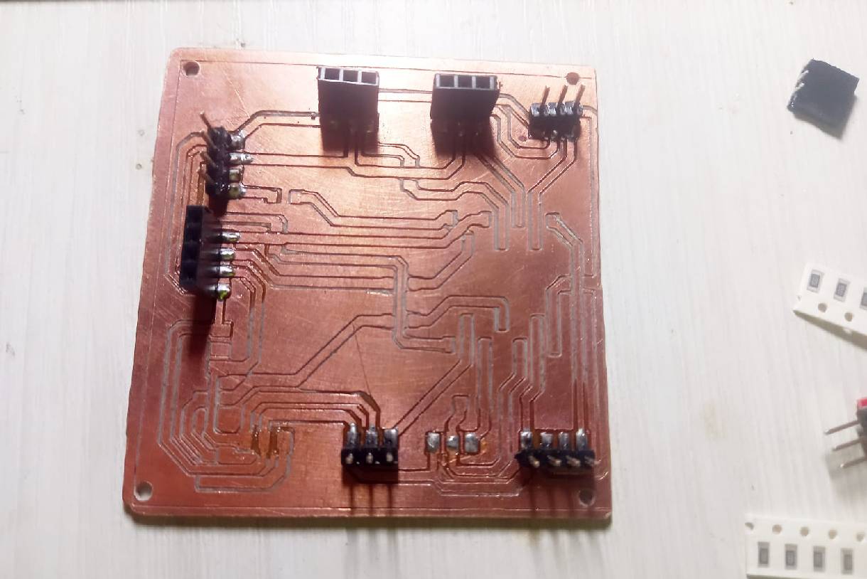
The welding process continues until the last component is completed. It is important not to change the values of the resistors, since this project was calculated using the values specified in the components list.
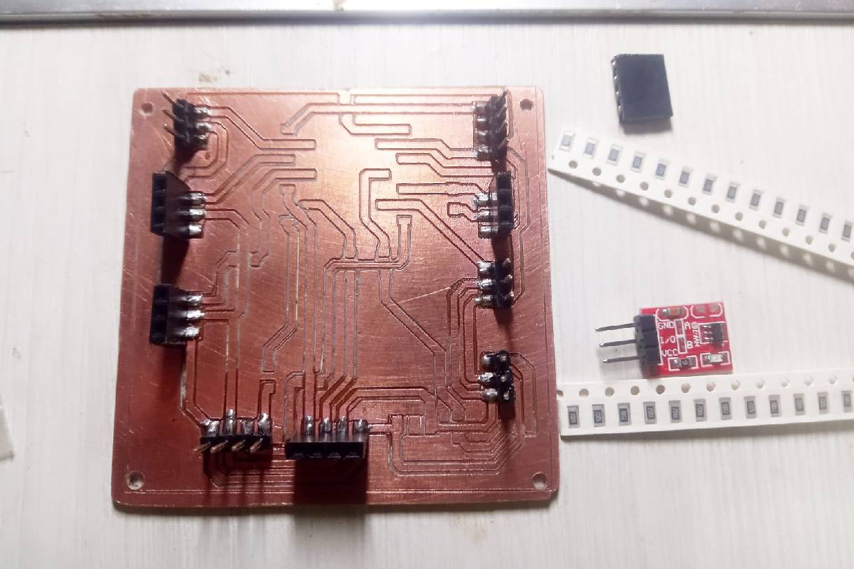
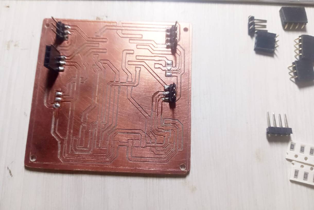
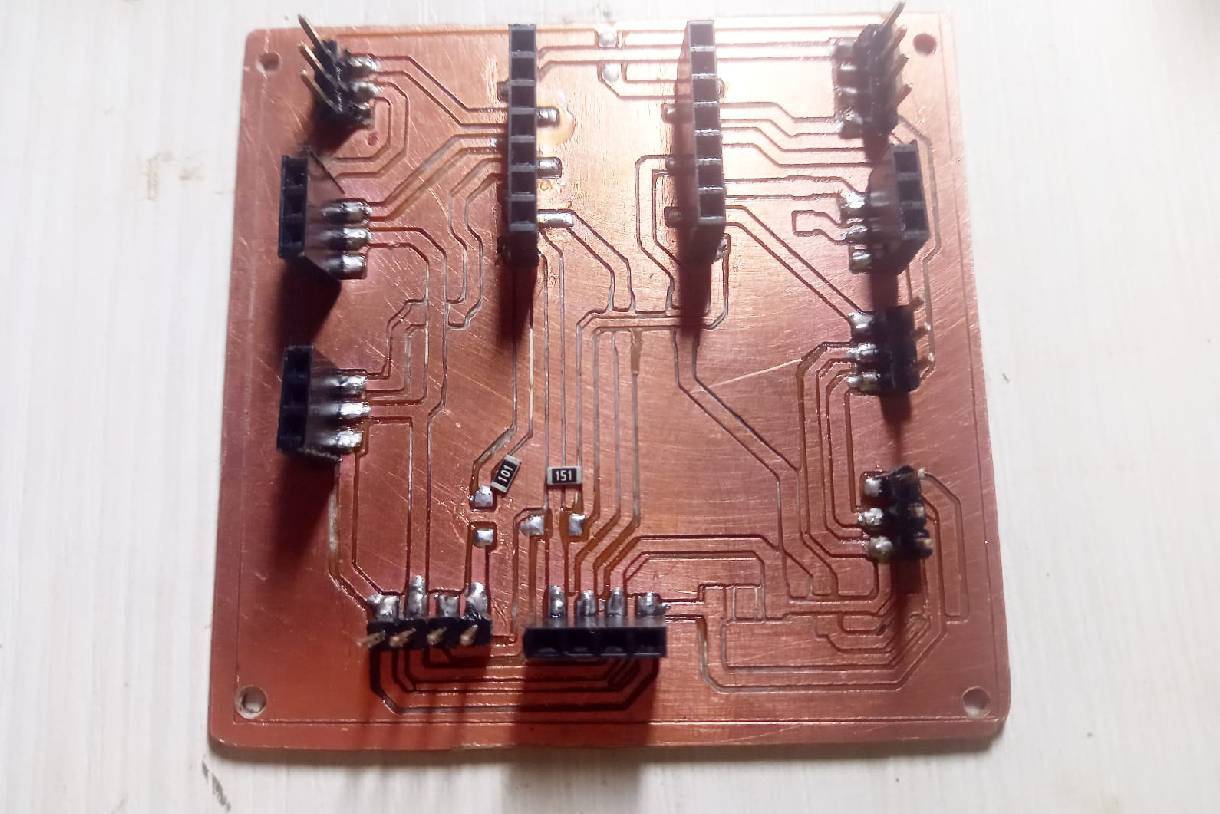
The following image shows the components already soldered and the sensor connections ready for the first test, which will be carried out after programming.
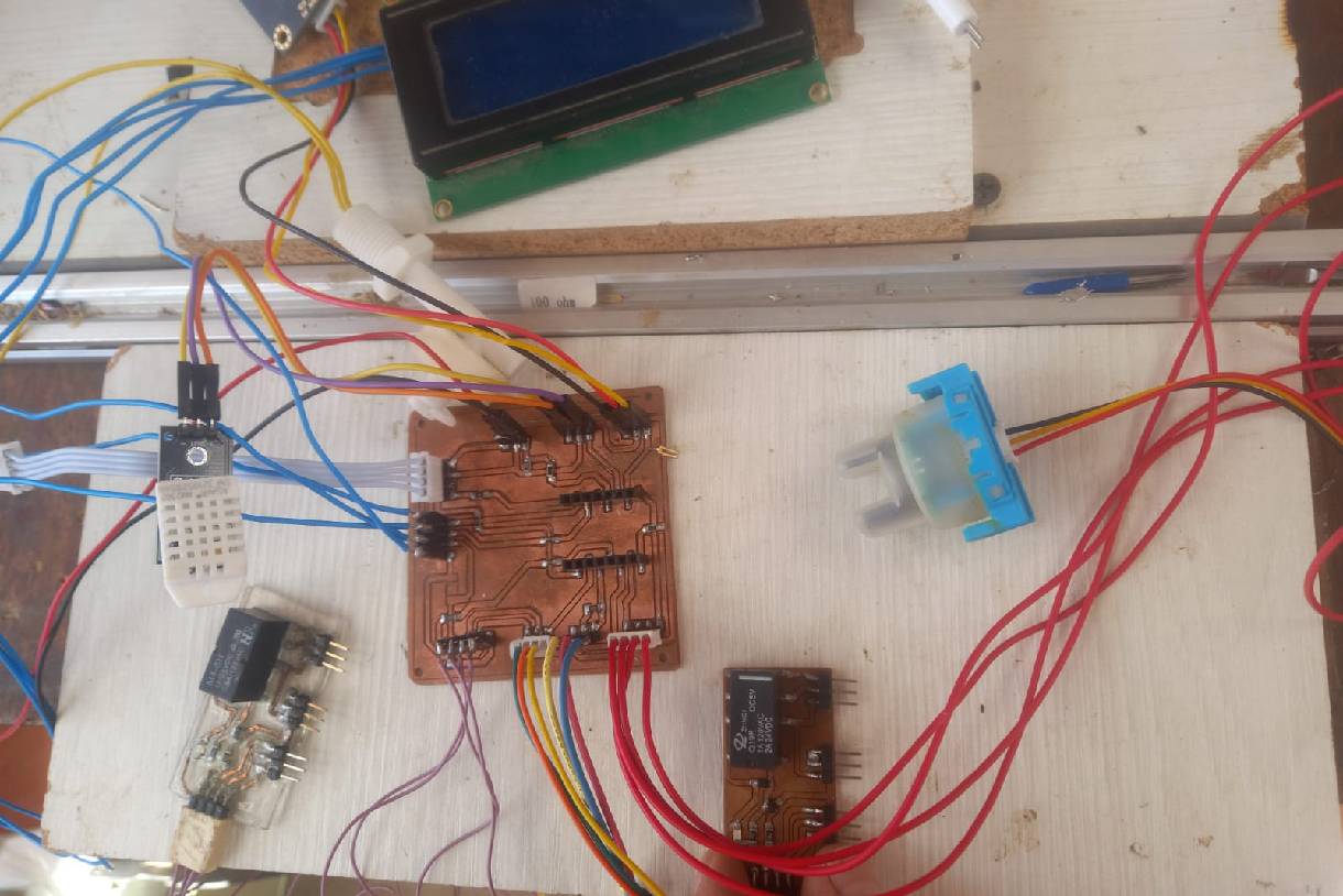
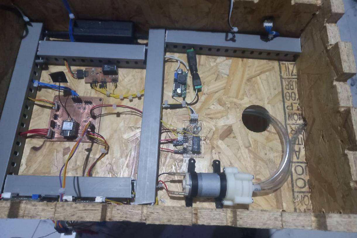
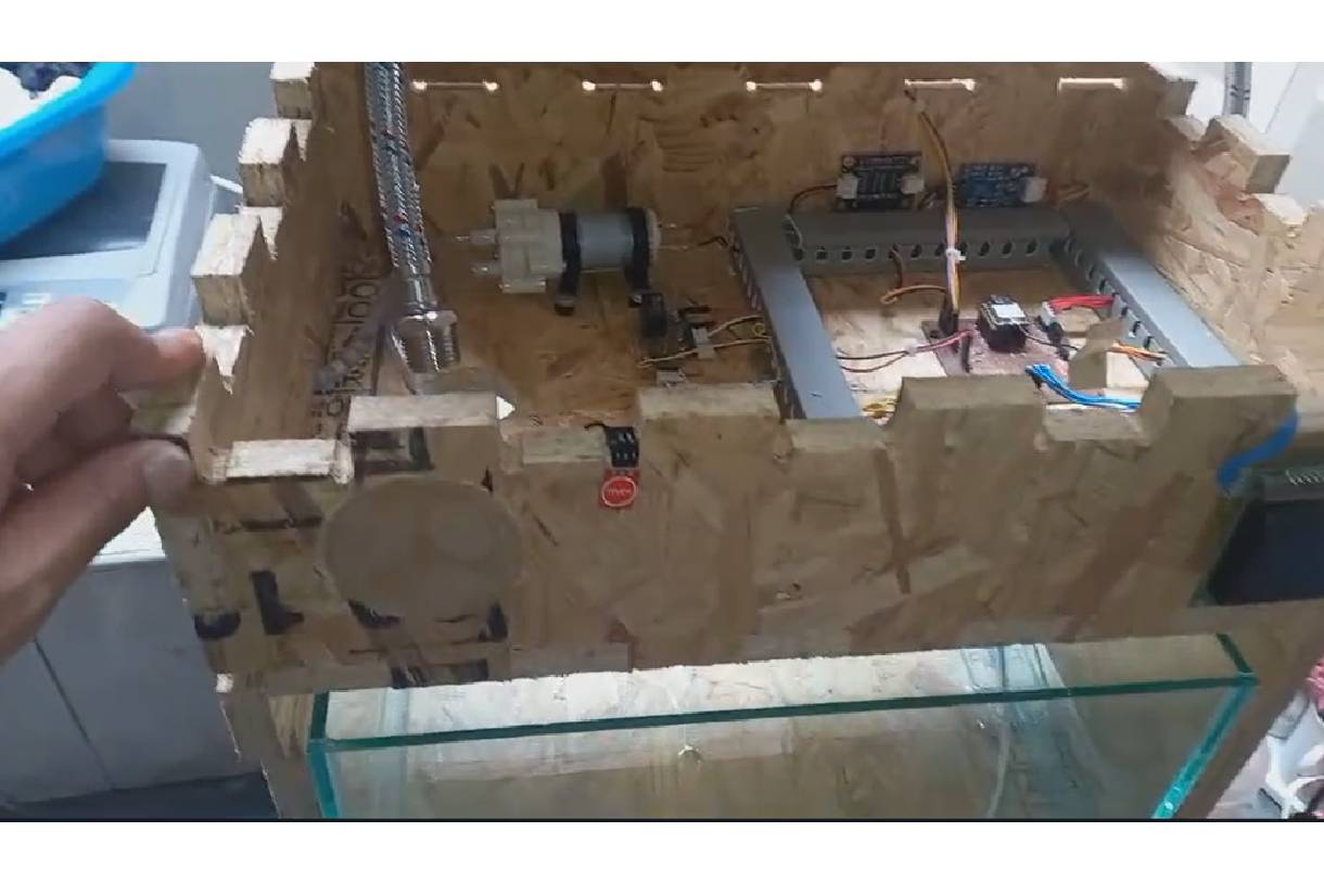
To integrate the project, several components were merged: the casing made of OSB material, an electronic board equipped with sensors such as TDS, turbidity, level, DHT22, Touch, and actuators such as a mini peristaltic pump and a solenoid valve.
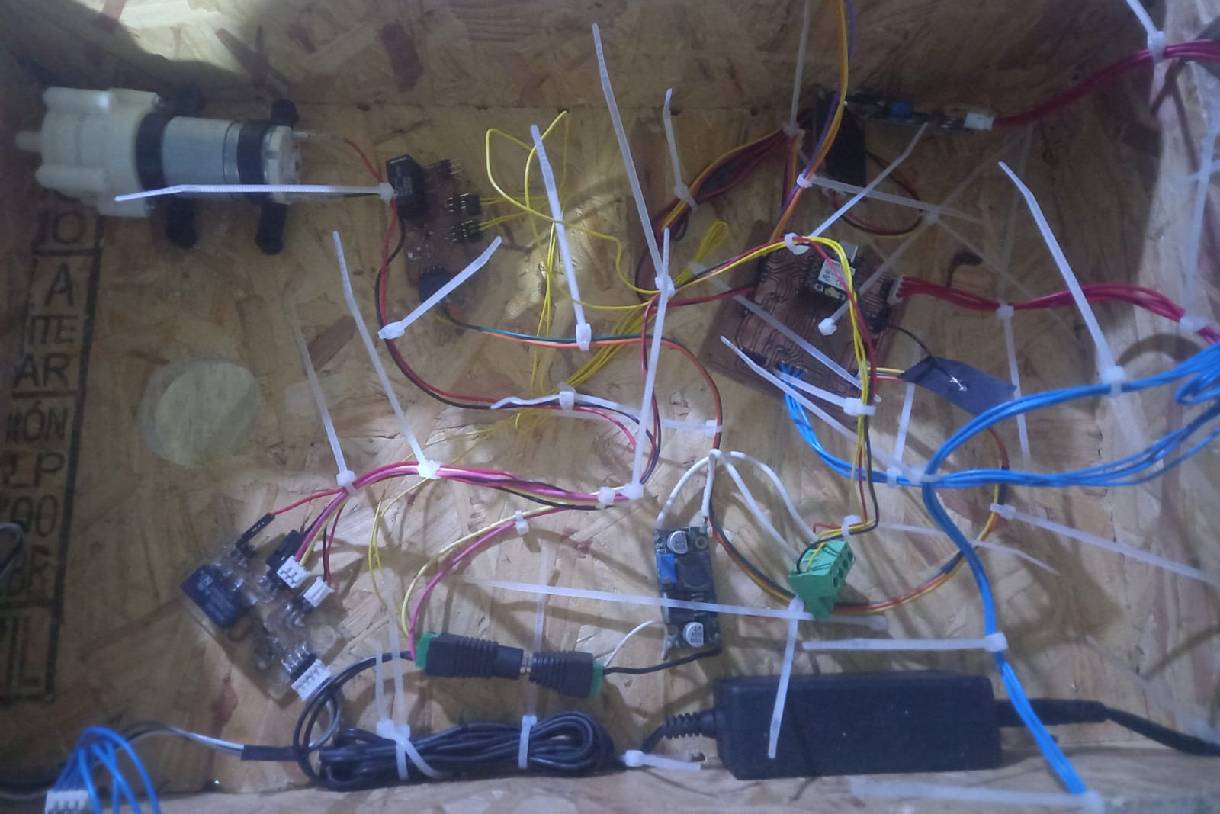
In the image, you can see that we must first make sure that the sensors are well connected and then group them with nylon ties according to their location. Subsequently, they are organized using the slotted gutters.
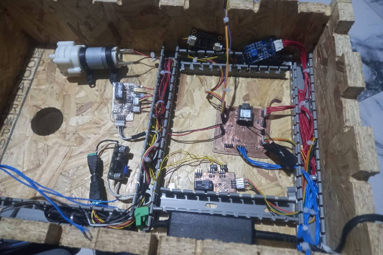
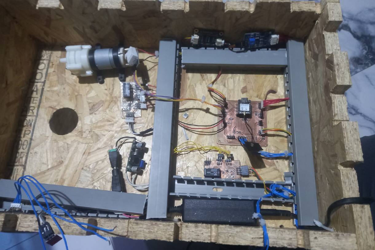
After securing the channels and organizing the cables on them, the next step is to add the final touch by placing the channel covers.
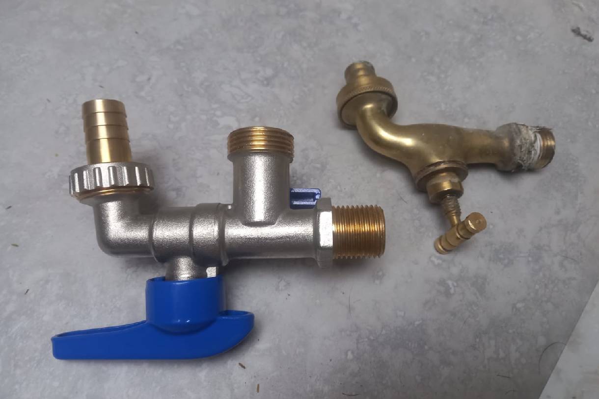
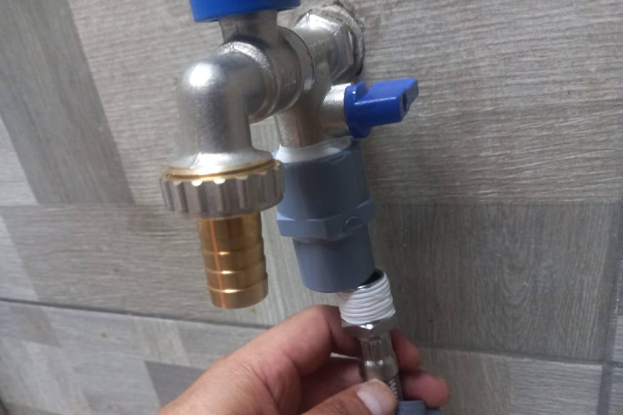
To install the solenoid valve, it is first necessary to change the one-outlet tap for a two-outlet tap. The solenoid valve will be placed in the second outlet of the new tap.
This process involves changing the old faucet for a two-outlet faucet. It is important to apply Teflon tape to the inlet thread of the new faucet to ensure that there are no water leaks.
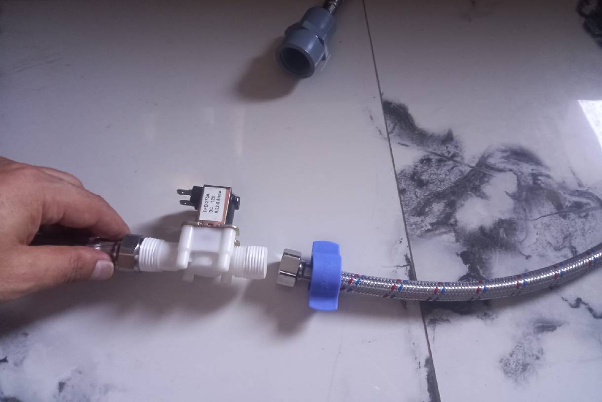
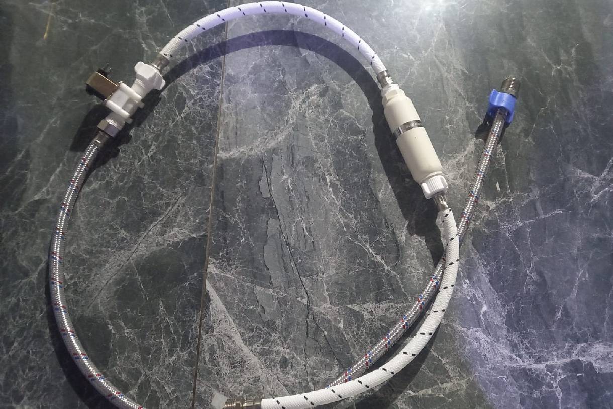
The next step is to attach or connect the flexible metal hoses to the solenoid valve, making sure to apply Teflon tape to ensure there are no leaks, as shown in the message.
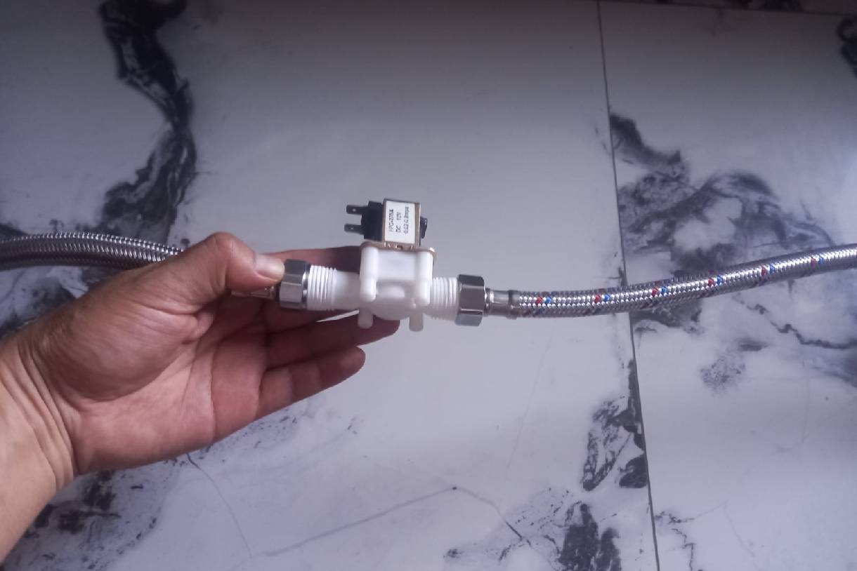
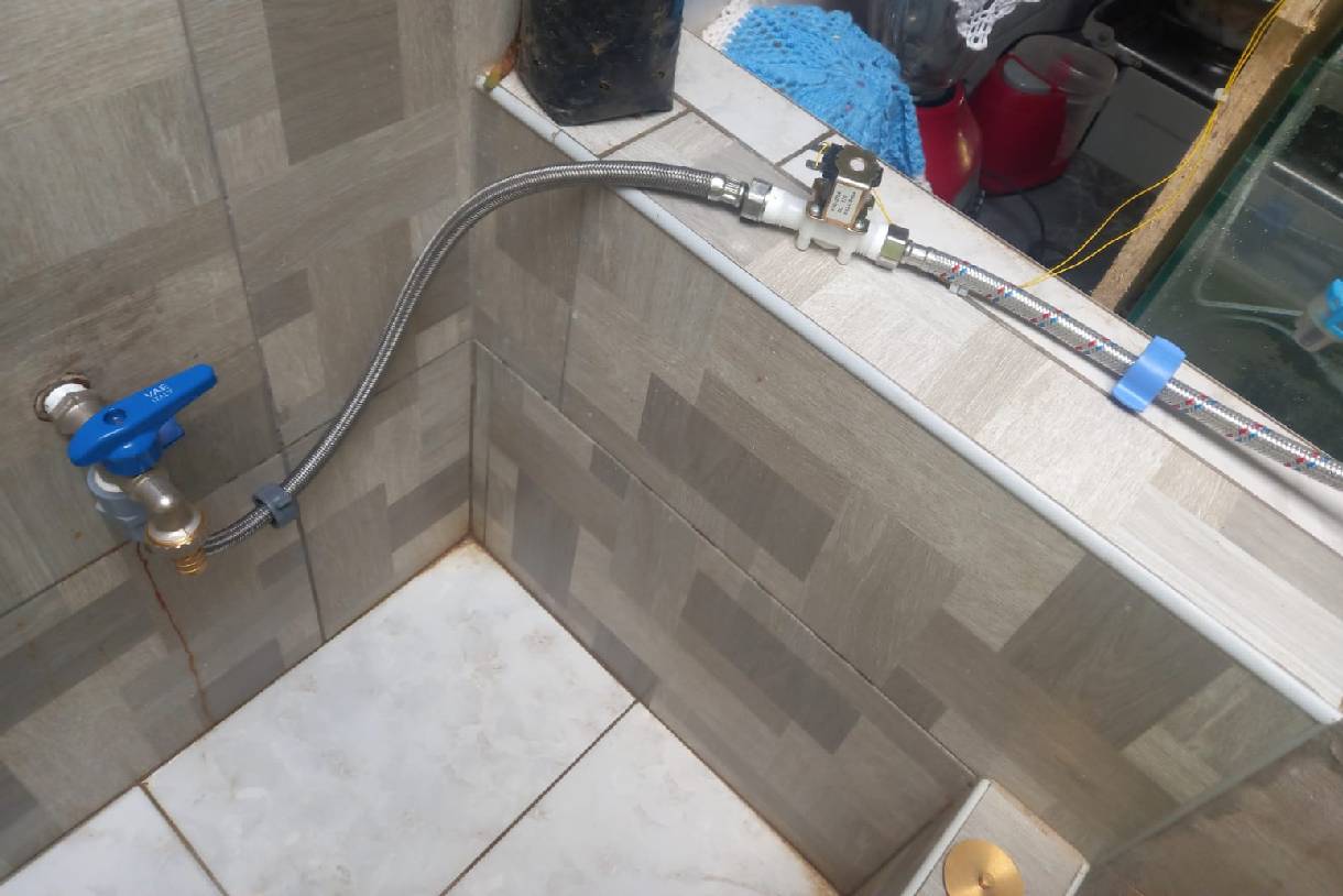
As a final step, one end of the hose is connected to the faucet, while the other end is directed toward the project.
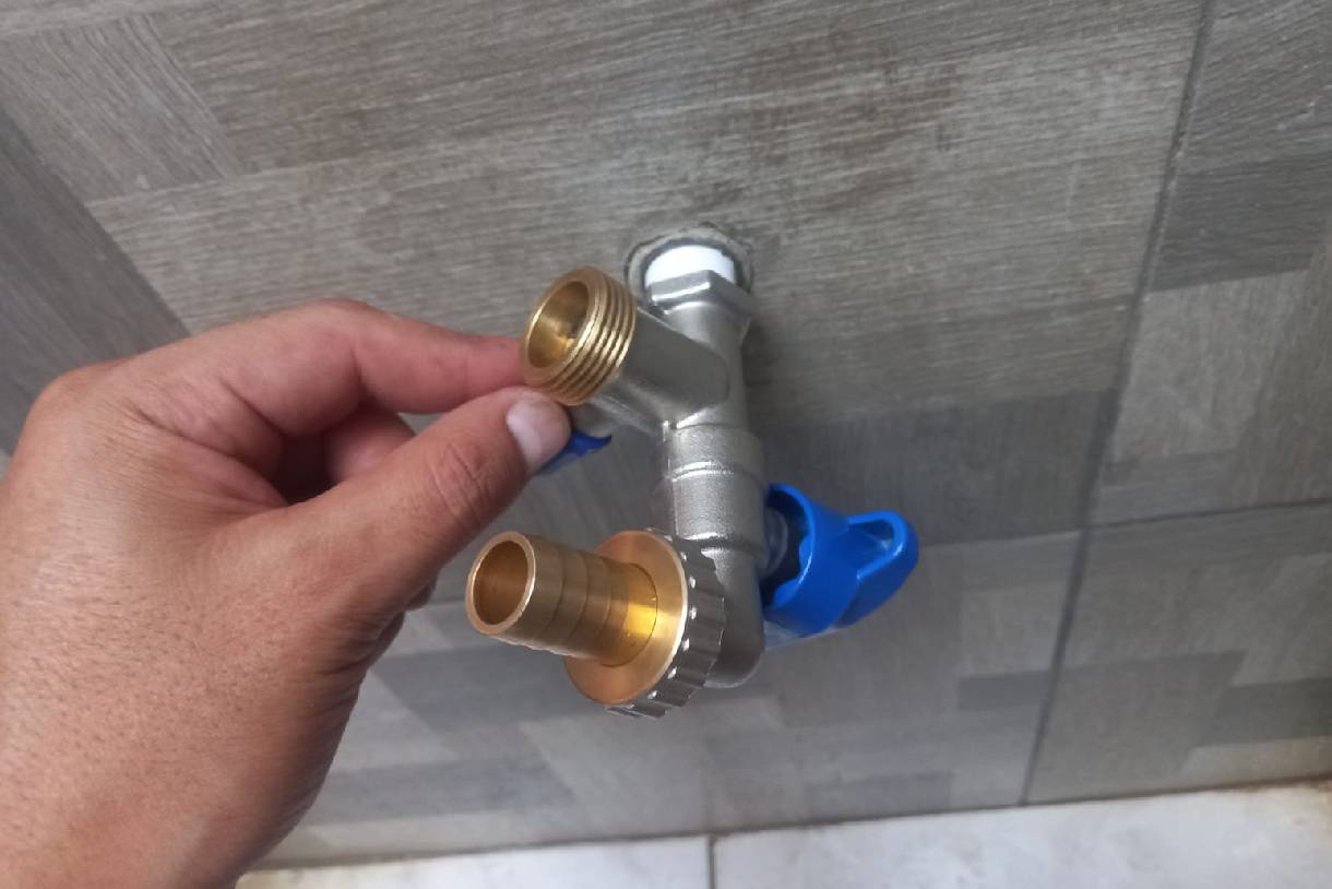
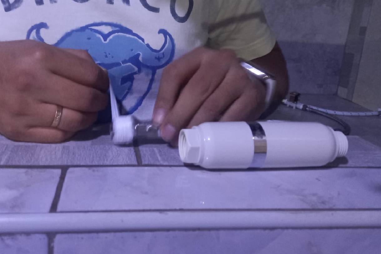
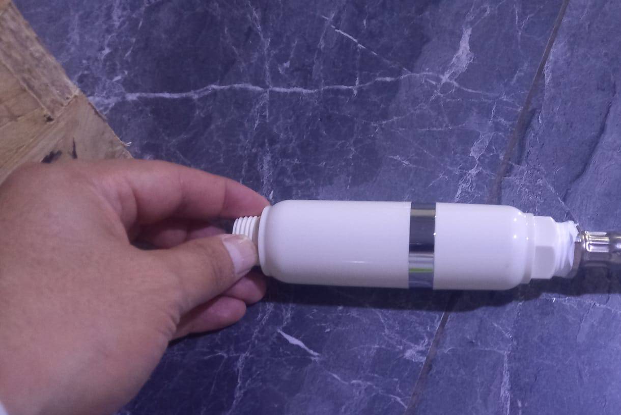
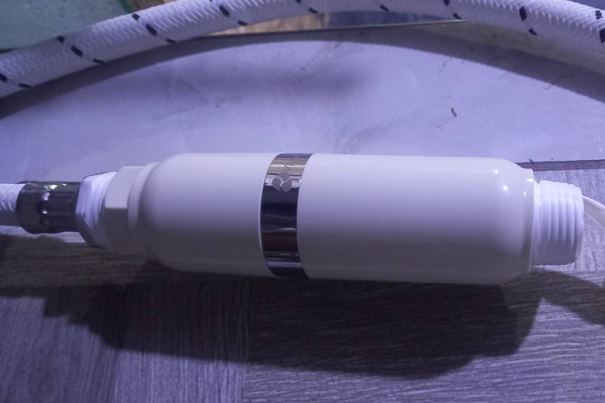
To connect the filter to the main faucet, Teflon tape was used to ensure greater tightness. Very carefully, it was installed in sequence with the solenoid valve.

Once the solenoid valve is installed on the faucet, the next step is to connect the other end of the flexible hose to the top hole, which in turn is connected to the rectangular glass tank or reservoir.
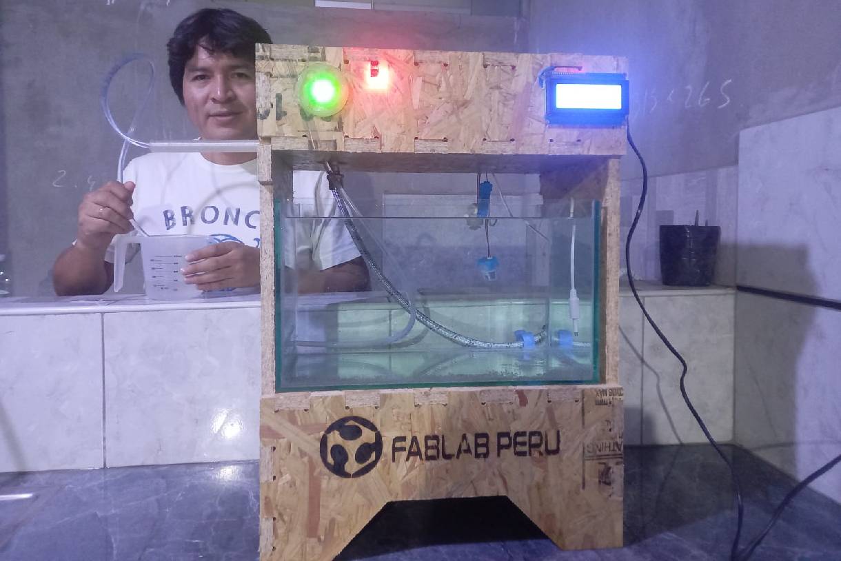
The following image shows the project ready for its first use, that is, first tests
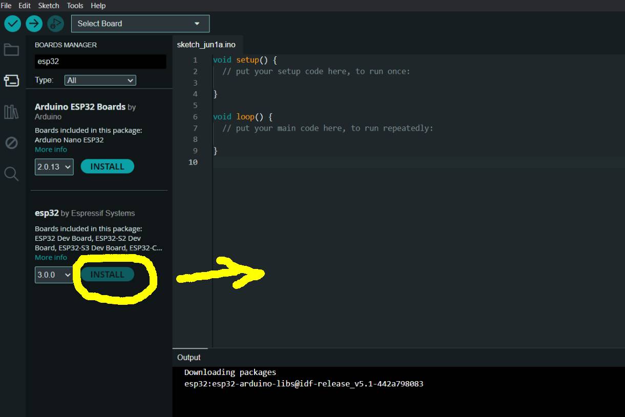
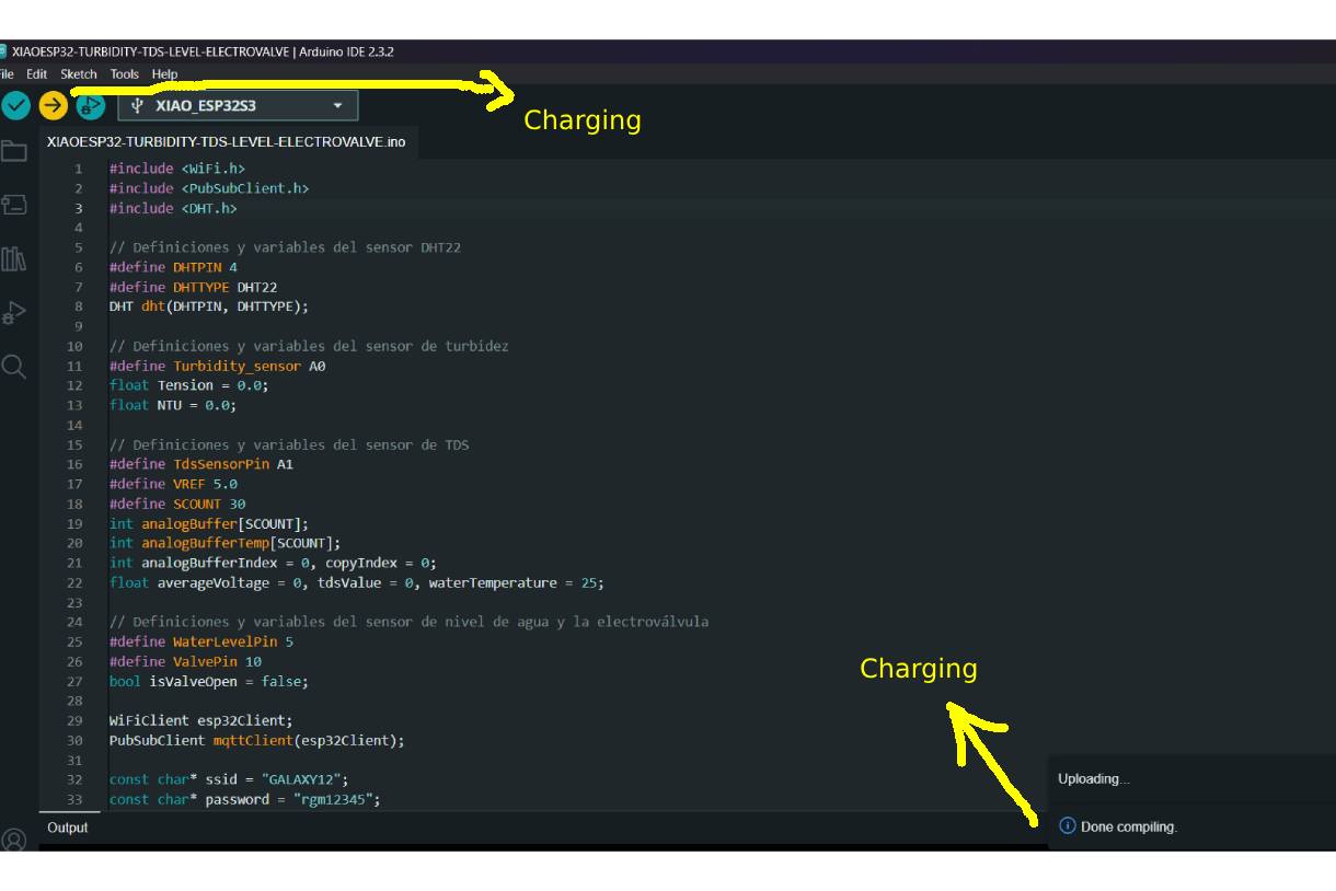
To carry out the readings and operation tests, I used the Arduino IDE with the XIAO ESP32-C3. In the development, I included the necessary libraries for the sensors and components of the project, such as WiFi, PubSubClient and DHT. These libraries are essential for the operation of sensors such as DHT22, turbidity, TDS, level, and other components necessary for the project.
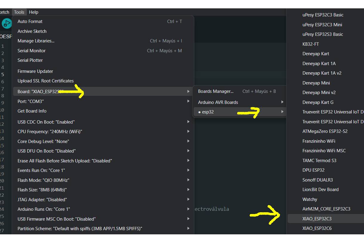
For installation, it is important to identify which is the appropriate package for our board. In my case, I installed the esp32 by Espressif Systems package. Next, I selected the XIAO ESP32-C3 board, as you can see in the following images.
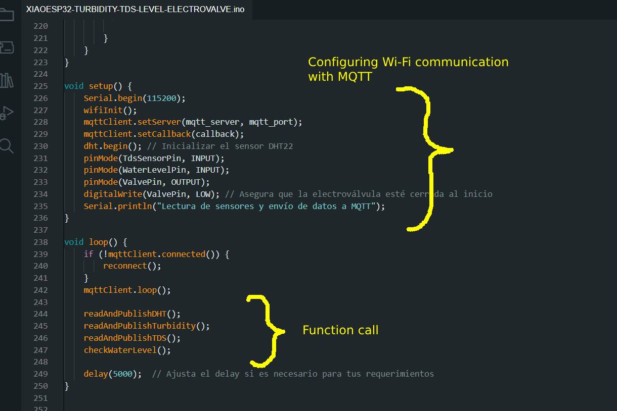
In the following image you can see the source code where it is seen that the sensor readings are being taken and sent in real time through MQTT using WiFi. Subsequently, the charging process can be displayed on the XIAO ESP32-C3 board.
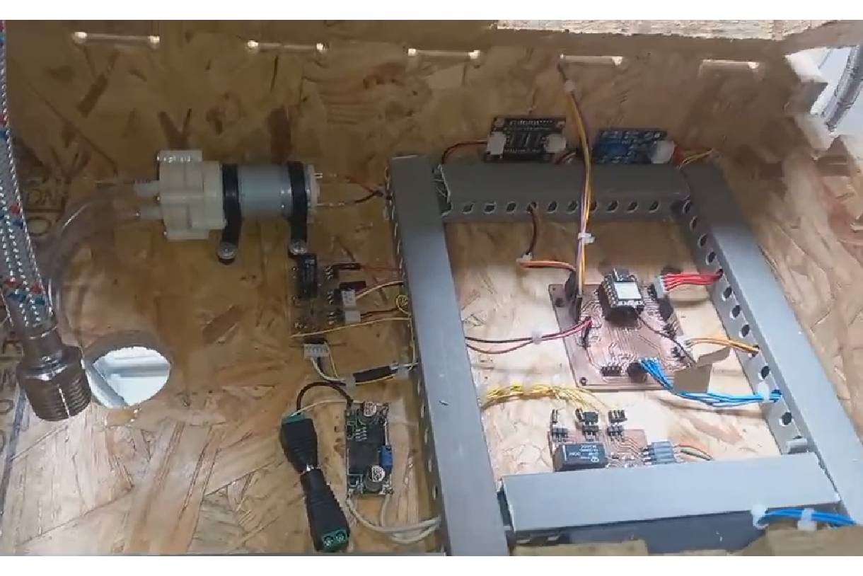
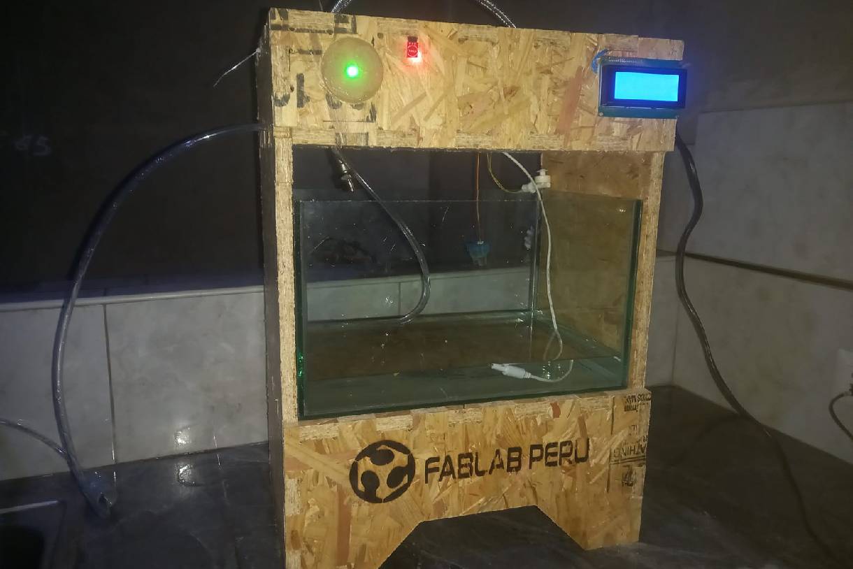
The following images show the first tests of the project, where the ignition and operation of the pump that feeds the tap can be seen.
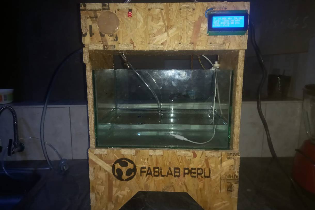
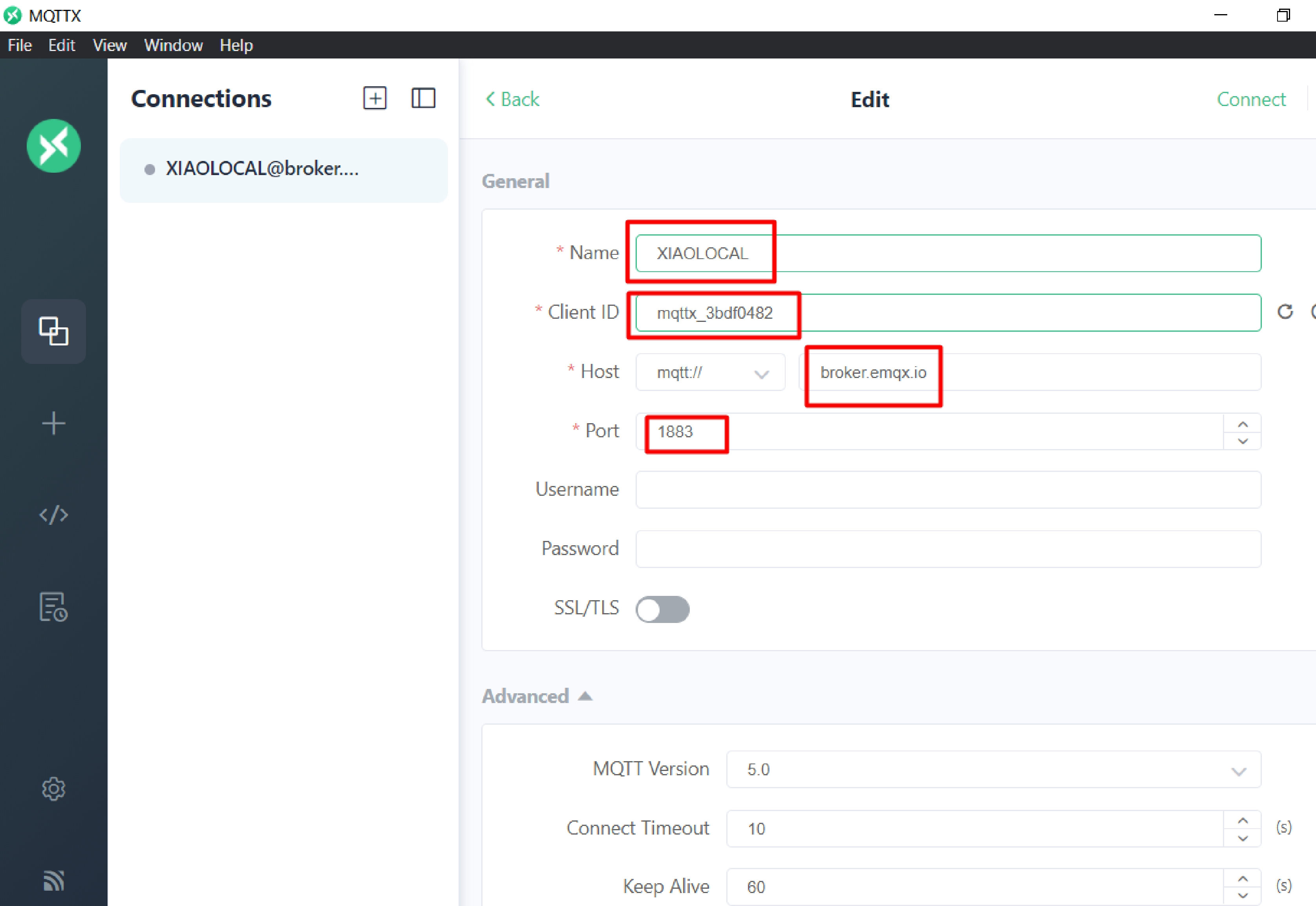
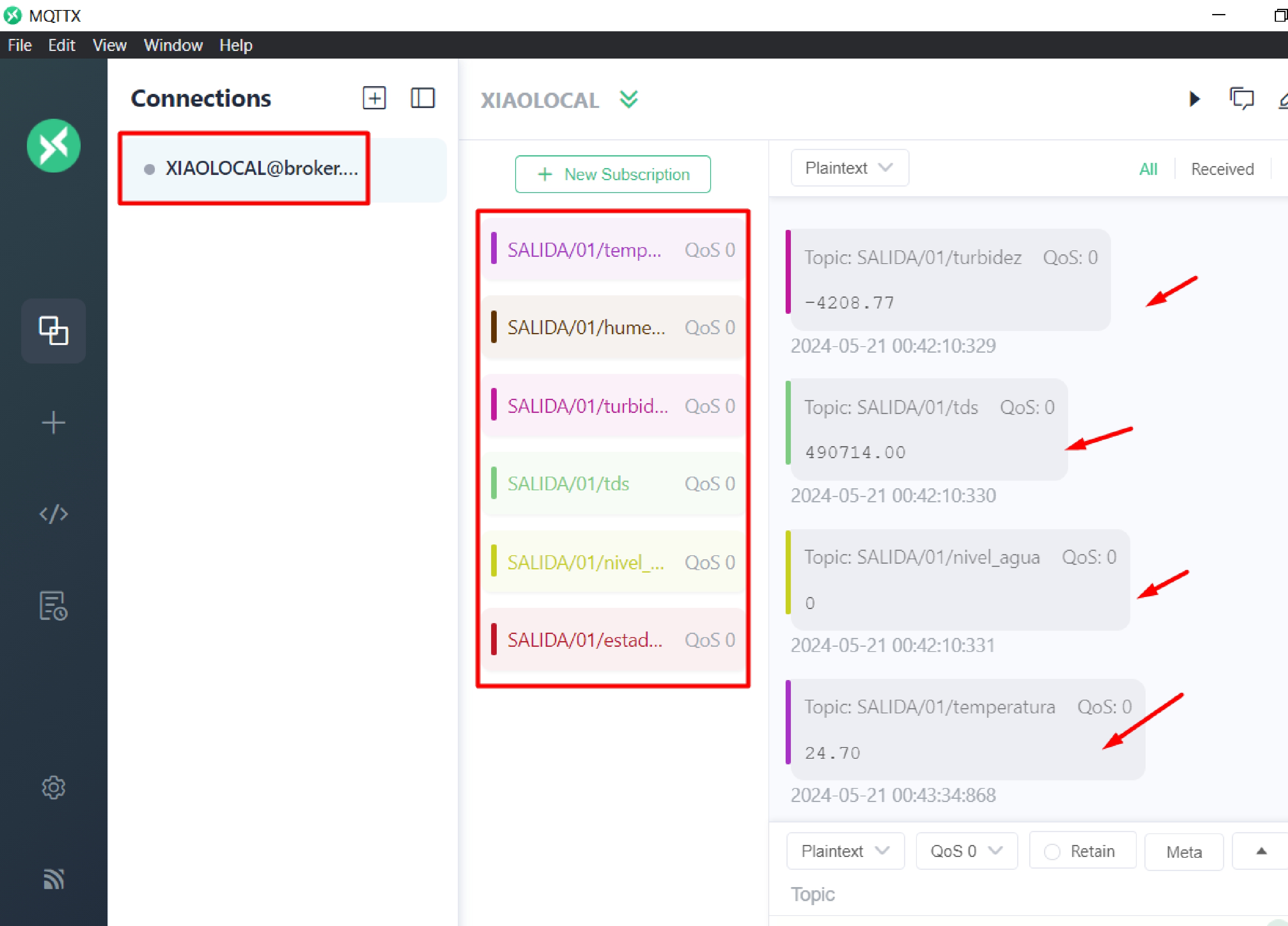
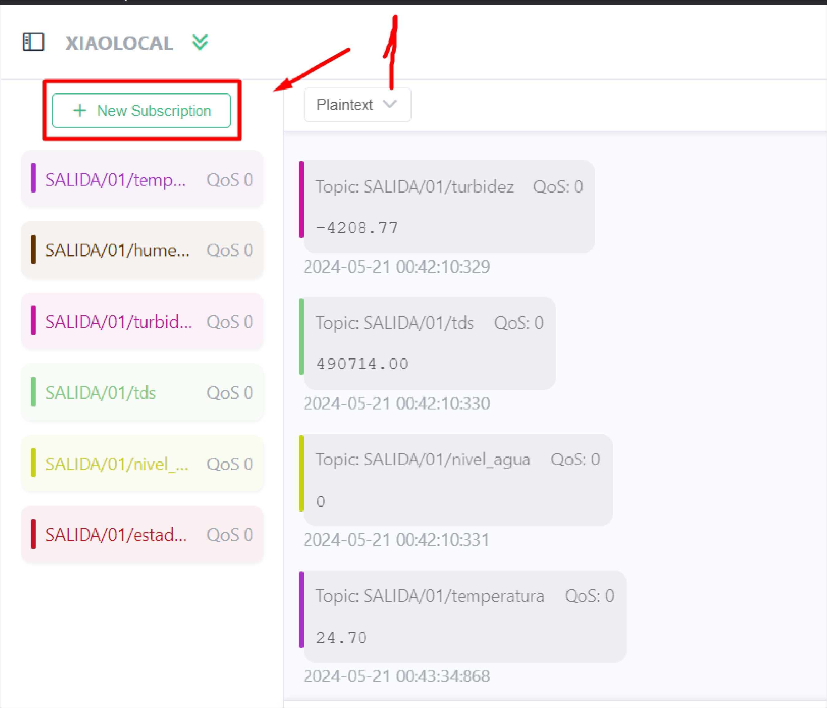
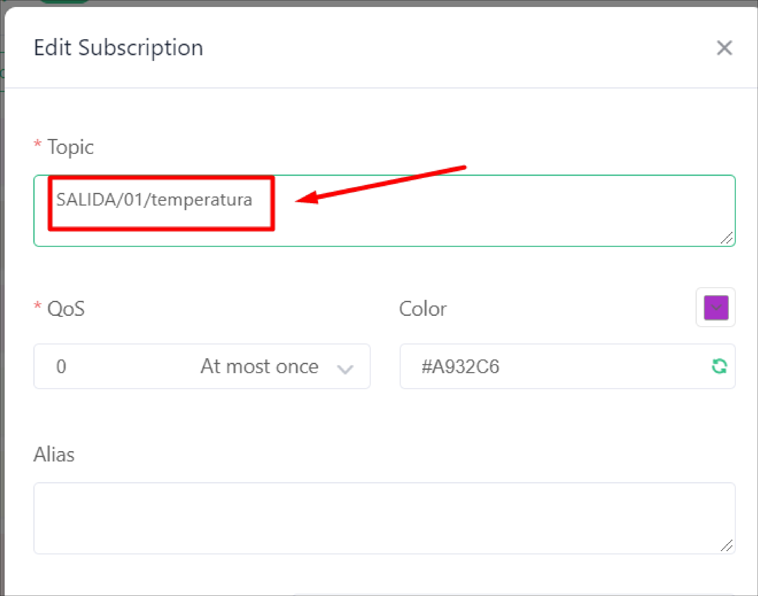
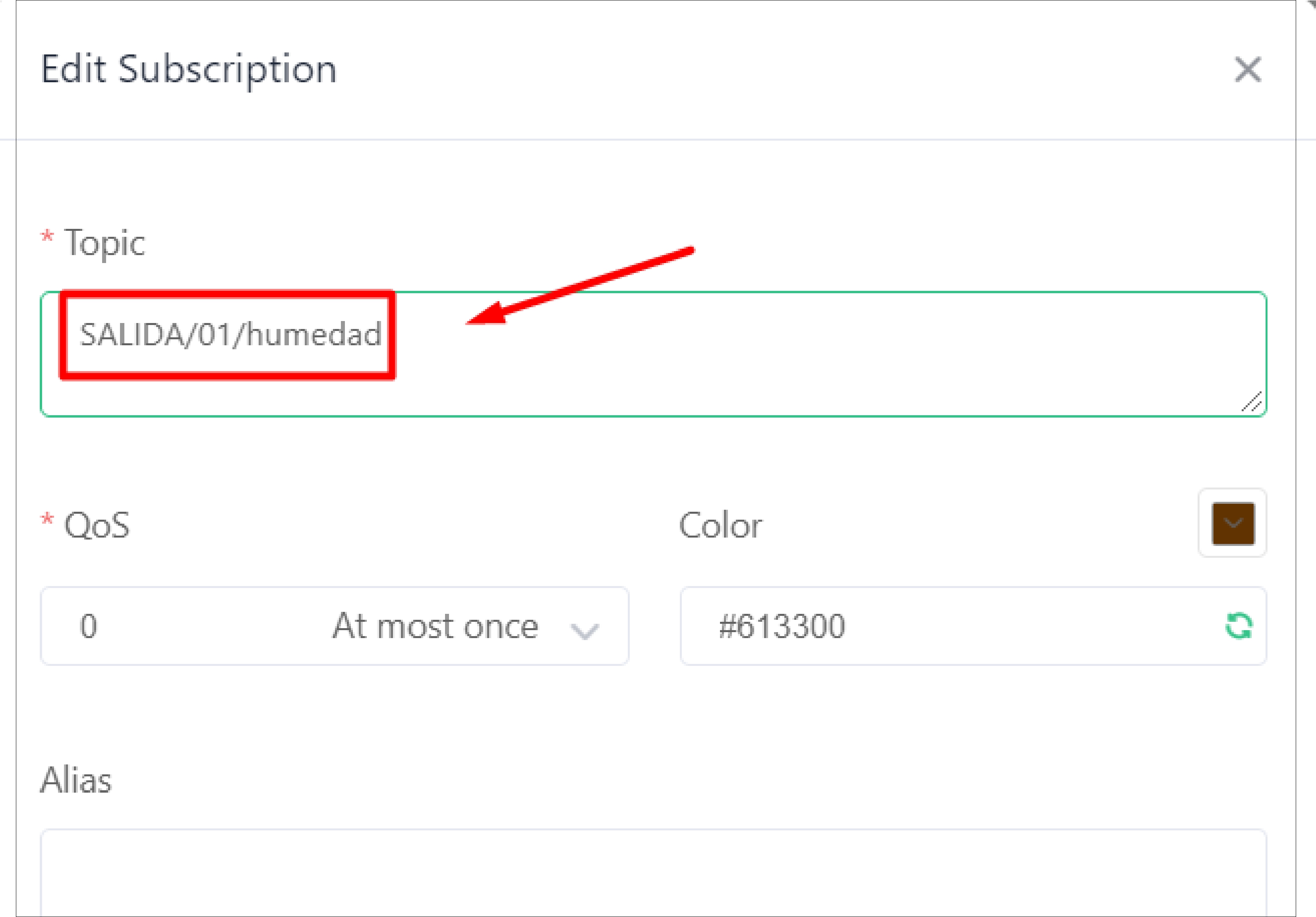
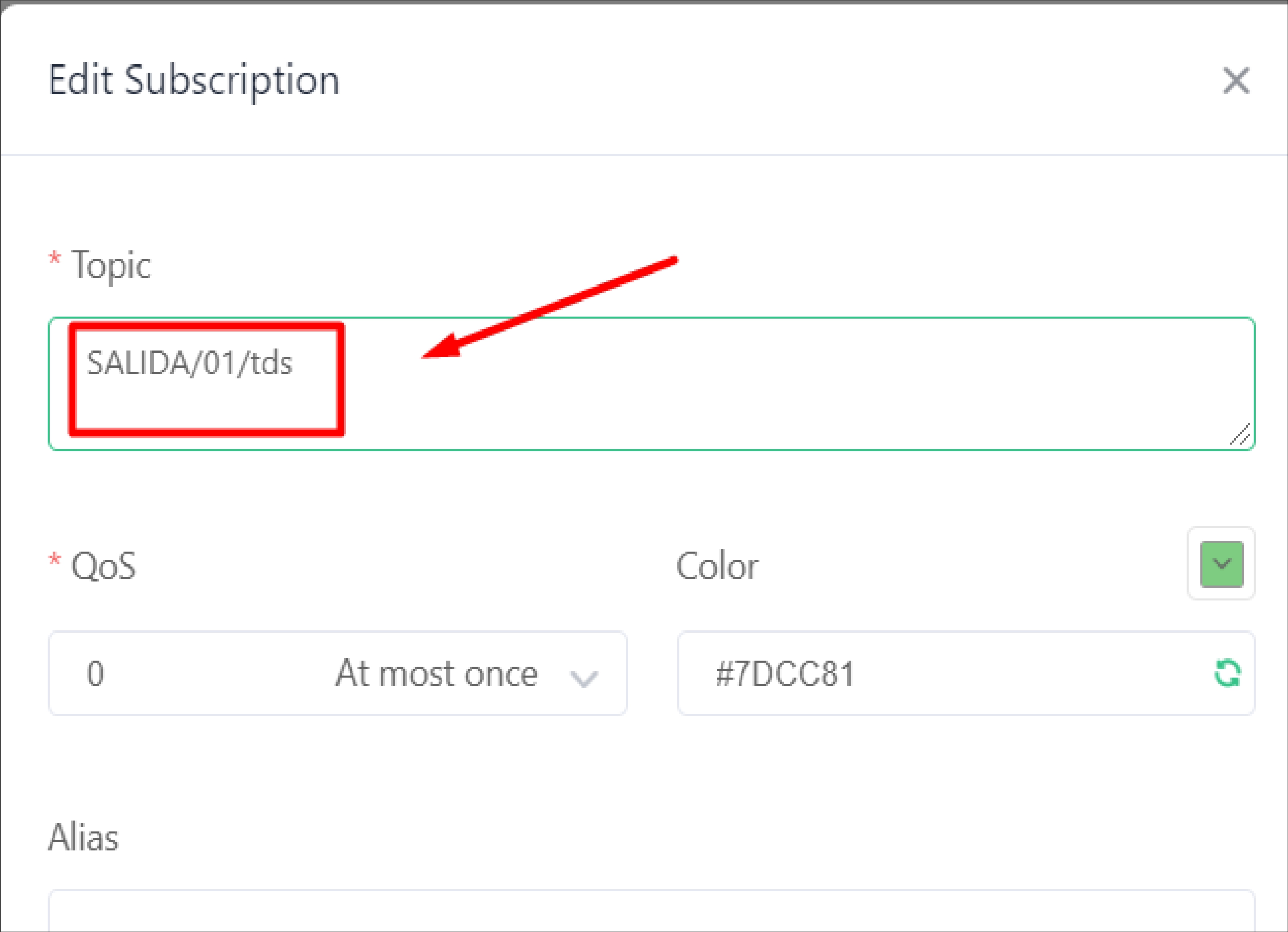
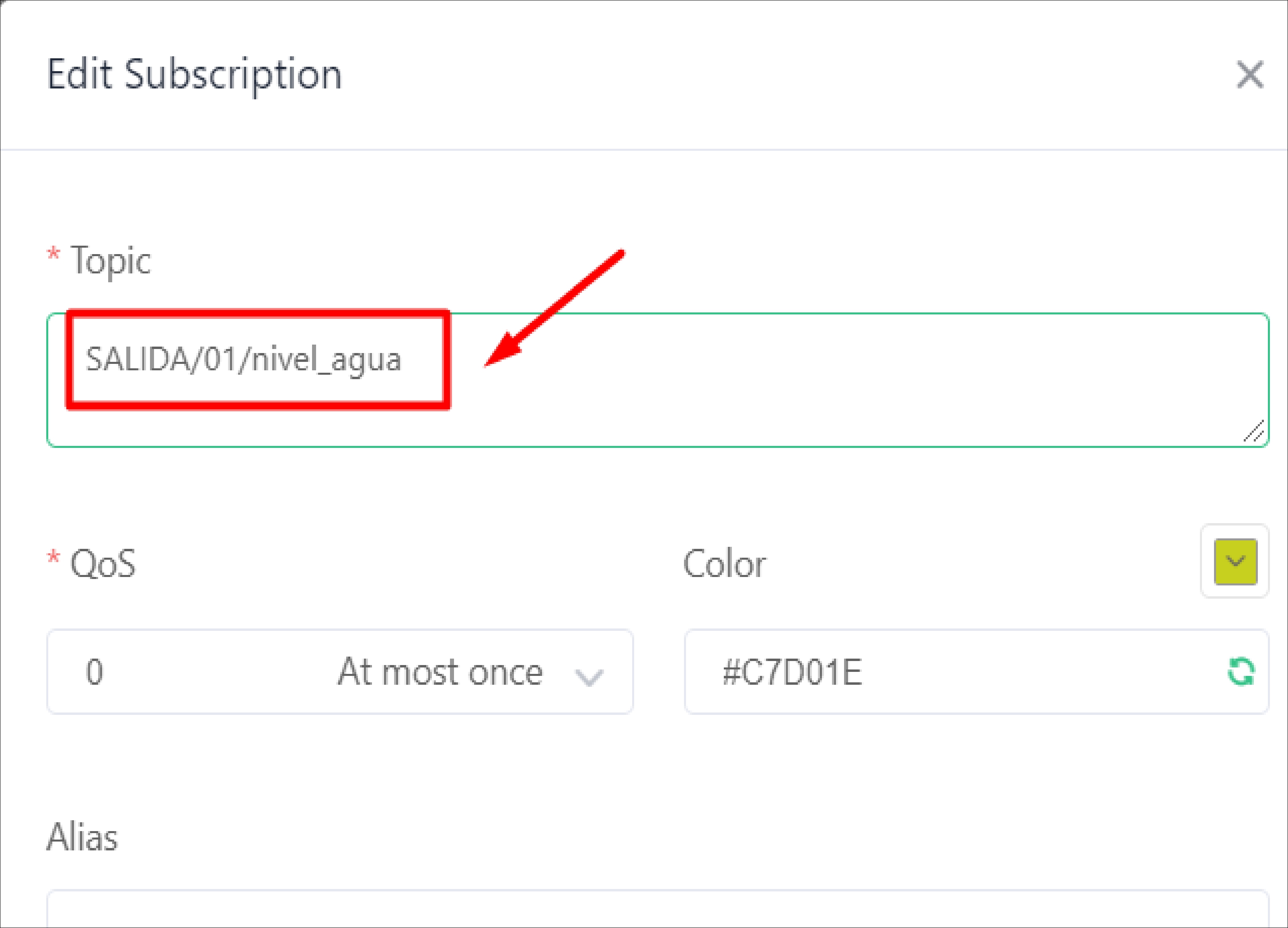
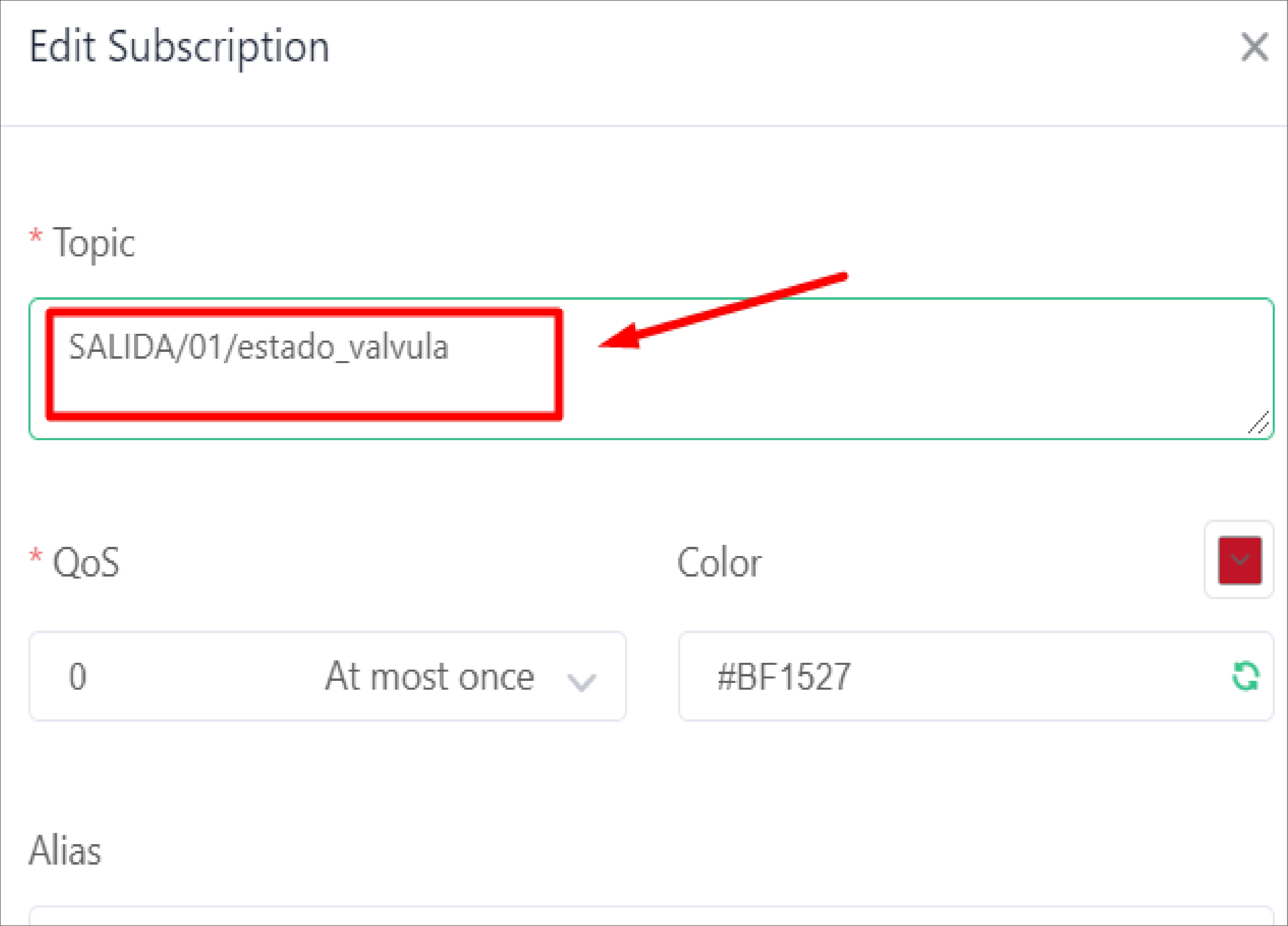
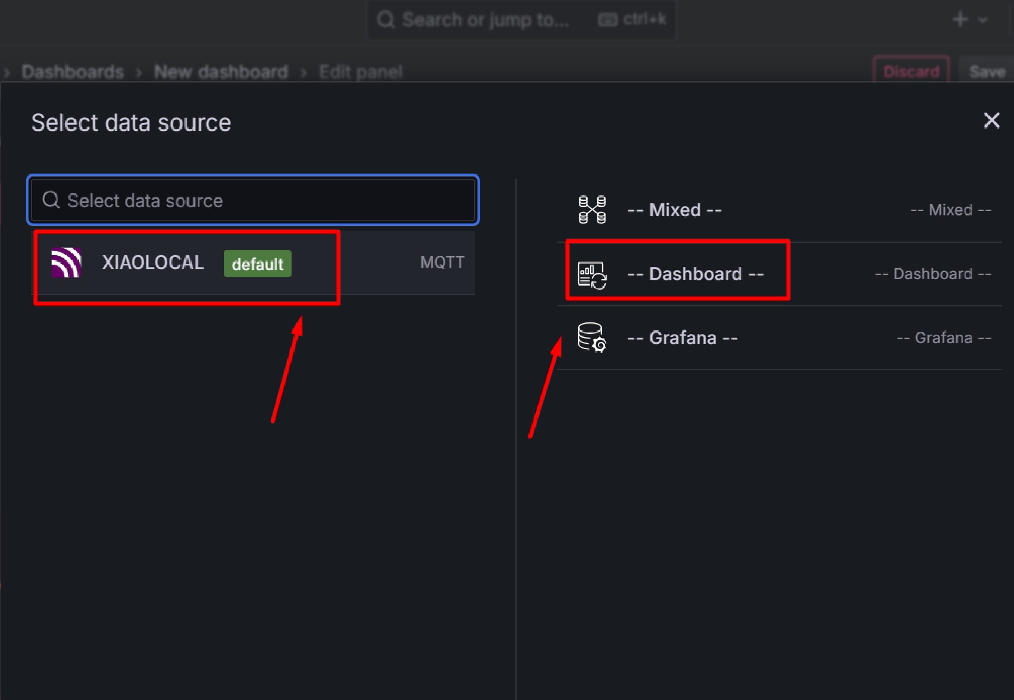
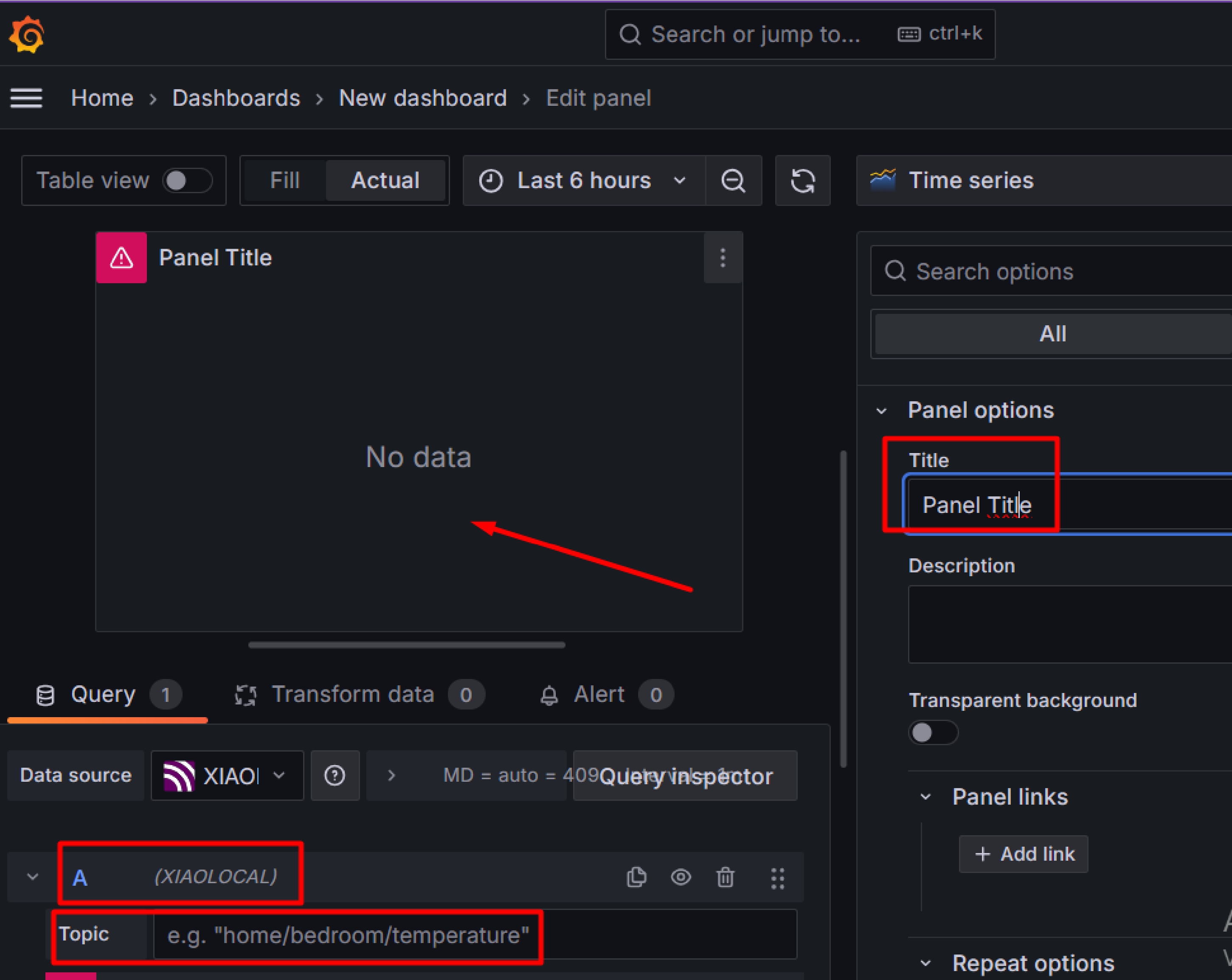
Reading the sensors with the XIAO ESP32-C3 and sending them to MQTTX is very useful to me, as it allows me to verify if the values are working correctly without having to physically check the equipment. I can see the data in real time in their dashboard and later get a better visualization in the Grafana dashboard. Additionally, I can configure the type of graph I want for my sensors, making it easy to analyze the data.
This project has given me great experience and satisfaction upon completion. Although I know it can improve, I already took the first step and I am happy to be able to use it. The Fab Academy was a great help to me, improving my skills in many aspects. Before, I only used Eagle design software, but now I also use KiCad. Also, I had never done a project with snap assemblies, but now my project is completely based on this method, something I learned at the Fab Academy. Thanks to this, I can make furniture and other projects without the need for nails or screws. I also learned how to use MQTT with the Grafana server to read my "IoT" sensors, something I didn't know about before. Now, I can carry out projects that integrate multiple tools and processes. All this learning in recent months has significantly marked my life.
Development of custom electronic boards with CNC Router.
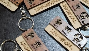
Development of personalized keychains and ornaments with CNC Laser.
Development of custom machines "Desktop CNC Laser.

Huánuco is a Peruvian city, capital of the district, province and department of the same name in the north-central area of the country. The city has a population of 235,529 inhabitants. .