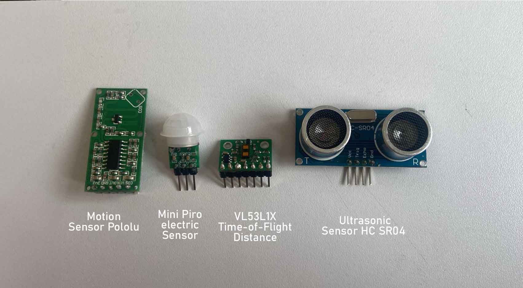
In the recognition of the components used, we have the Sensor Motion, the Mini Piro electric, the Time of Flight and the ultrasonic, all of them are within the so-called input devices.
These devices were found in our inventory at Fab Lab Científica, of which the Mini Pyroelectric was not used, for the simple reason that it did not work.
Motion Sensor
A motion sensor or passive infrared (PIR) sensor is an electronic device that detects the movement of an object, anywhere within its field of view, by measuring the infrared (IR) light emitted from, or reflected by, that object
A motion sensor uses one or multiple technologies to detect movement in an area. When a sensor detects motion, it sends a signal to your security system's control panel, which connects to your monitoring center.
The Measure
In the first test we analyzed the frequency in milliseconds, starting in AUTO with 10 mS.
I went up the ms to appreciate more detailed levels, up to 7.60ms, the waves are much more followed each other, but can be appreciated more detailed.
We also analyzed the voltage and we can see that between one wave and another, the result was 4.48V.
Ultrasonic Sensor
The ultrasonic sensor is a non-contact type of sensor used to measure an object's distance and velocity. This sensor operates on sound wave property to measure the velocity and distance of the object (Souri et al., 2020)
measures the distance to an object using ultrasonic sound waves. An ultrasonic sensor uses a transducer to send and receive ultrasonic pulses that relay back information about an object's proximity.
The Measure
For the second test, we modify the time level to 2uS (shorter measurement time) and we can observe that the difference in the frequency of the waveform is minimal between the highest level it reaches and the lowest level. This is when we are making contact with the ECHO PIN of the sensor.
Time of Flight Sensor
Time-of-Flight (ToF) sensors measure distances using the time that it takes for photons to travel between two points, from the sensor's emitter to a target and then back to the sensor's receiver. Indirect and direct ToF both offer specific advantages in specific contexts.
ToF sensors typically use infrared light for signal transmission, which allows for efficient short to medium-range distance measurements. In contrast, LiDAR systems often employ more powerful laser light sources that can extend their operational range and provide detailed, high-resolution spatial data
The Measure
Then, when switching to the SCL PIN, we can see that the oscilloscope presents different data.
We see that the waveform changes and the frequency has a difference of 9.33 mS between the highest part of the waveform and the lowest part.
Individual Assignment
WHAT COMPONENTS I WILL USE
Detailing each component
Motion Sensor
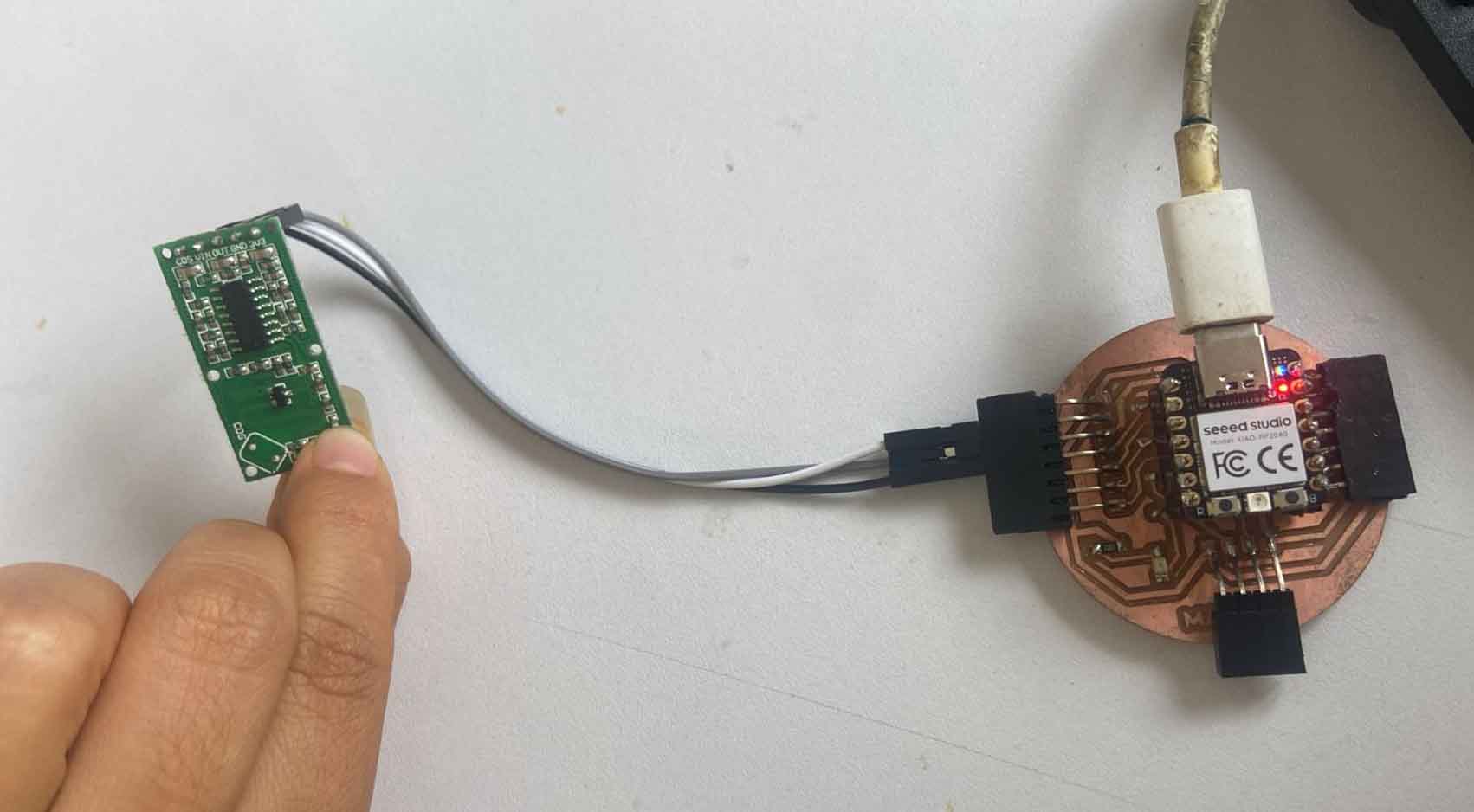
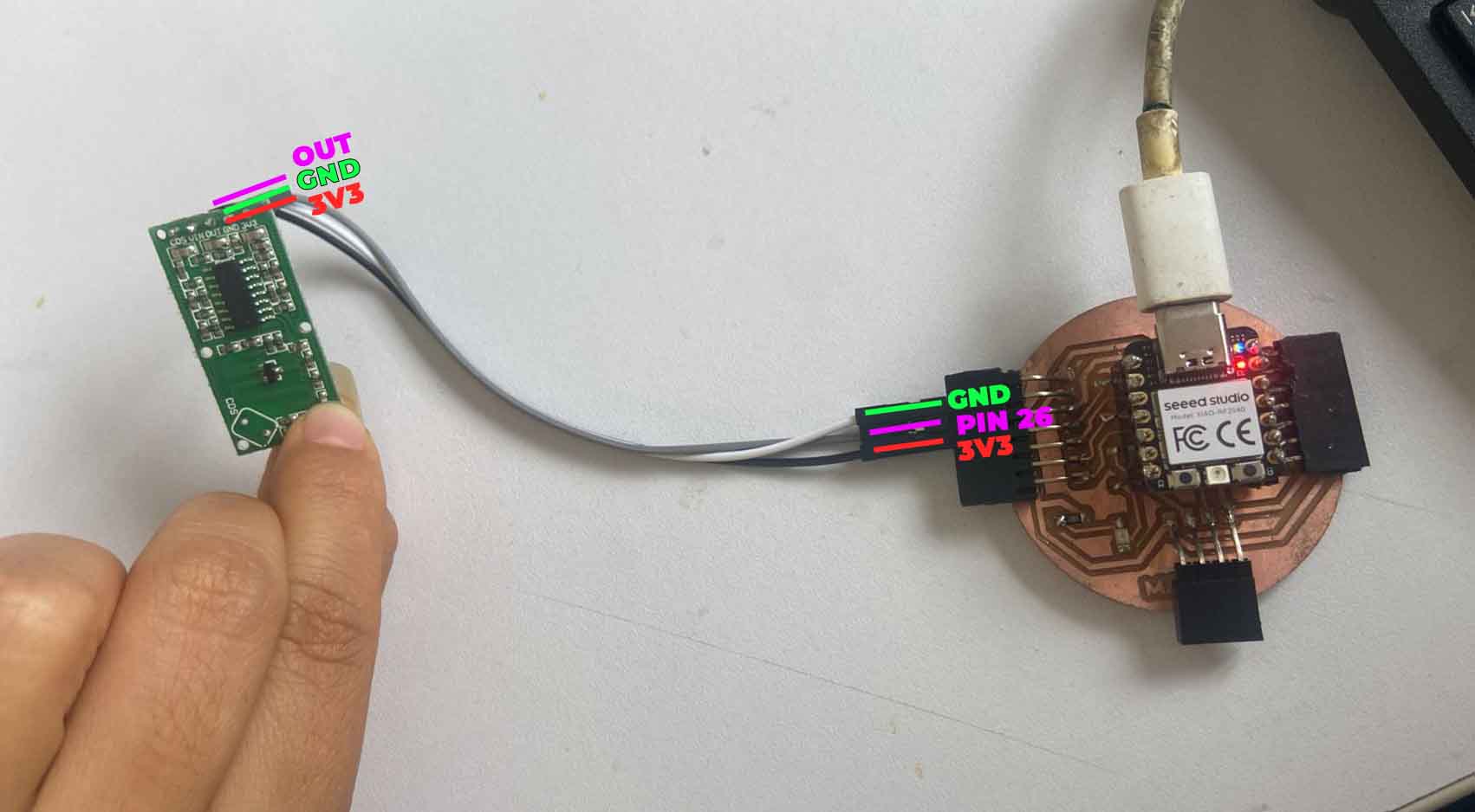
Starting with the motion sensor, it is connected to the development board using the 3 pins of the sensor, the 3V3 power supply, the GND and the OUT to achieve its operation and reading.
First the 3V3 sensor pin is connected to the 3V3 of the development board. In this case I will use black wire for identification as shown in the image.
Next we will connect GND with the GND of our development board, in this case I have used the white cable to identify it as it is seen in the picture.
Finally we will place the OUT pin of the sensor in the connector that has the PIN 26 for this test. For this case I used the gray wire to identify it.
Here you have a summary picture of the connection I made of the sensor with my development board. Now we connect the XIAO RP2040 with our computer to program it.
For programming, I used the ARDUINO IDE, here is the code I used.
// Define the motion distance sensor pin
    const int pinMotion = 26;

    void setup() {
    // Start serial communication
    Serial.begin(9600);
    // Configure the motion distance sensor pin as input
    pinMode(pinMotion, INPUT);
    }

    void loop() {
    // Read the state of the motion distance sensor
    int motionState = digitalRead(pinMotion);

    // If motion is detected
    if (motionState == HIGH) {
    // Print "movement" message on the serial port
    Serial.println("movement");
    } else {
    // Print "off" message on the serial port
    Serial.println("off");
    }

    // Wait for a brief period before reading again
    delay(1000);
    }
Here in the video we see that the ARDUINO code sends the signal in SERIAL when there is movement while it is OFF when it does not perceive it.
Here is an example video, where we see that the sensor sends a signal in SERIAL when it detects MOTION and OFF when it does not detect motion.
Ultrasonic Sensor
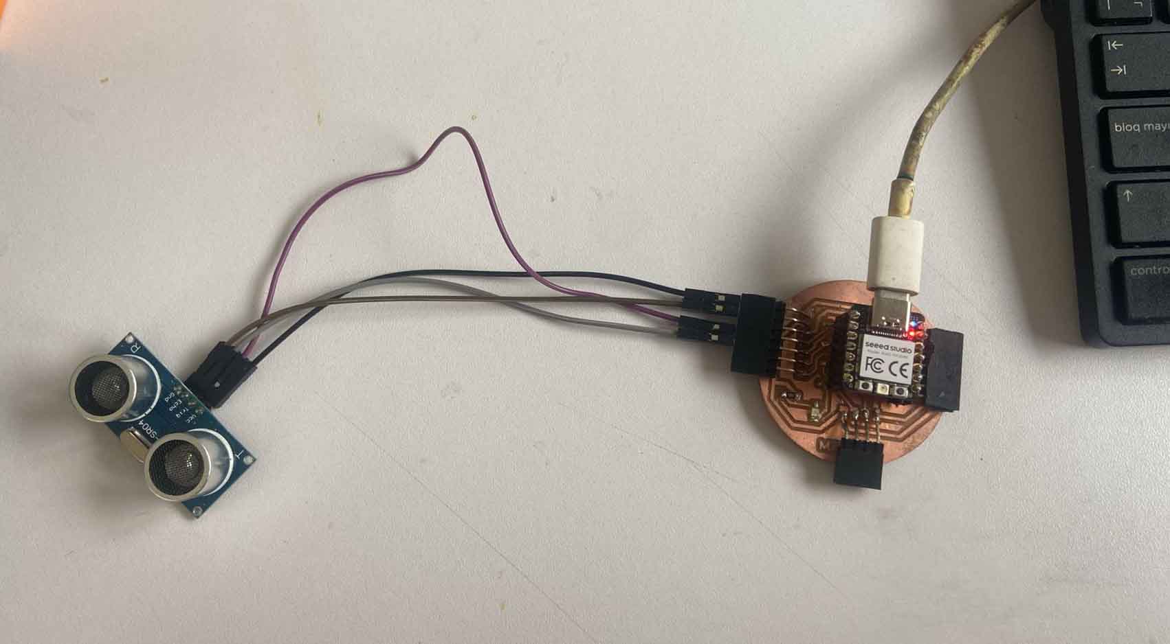
The next one is the ultrasonic sensor, it is a device that uses high frequency sound waves to measure distances between the sensor and an object, commonly used in proximity detection and distance measurement systems.
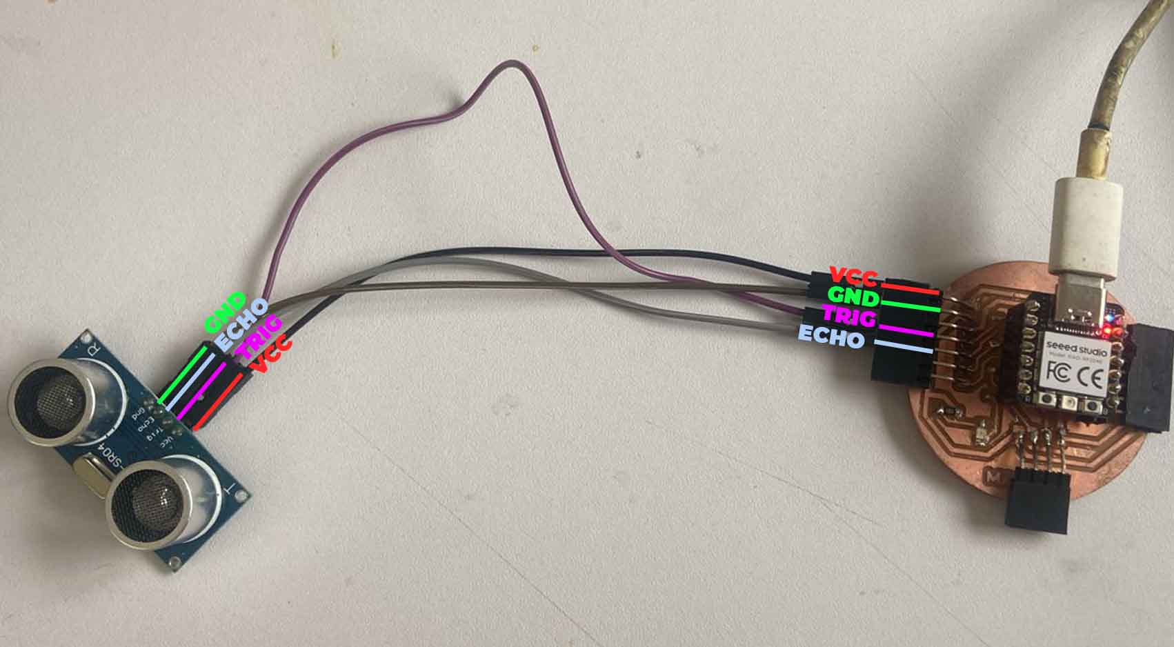
First we connect the VCC pin of the sensor to the 5V pin of the development board, to identify it we will connect it with a black wire.
Then the TRIG pin of the sensor is connected to one of the pins of the development board. For it we will connect it with the PIN 26 of the XIAO RP2040 identified with the light gray cable.
In the same way, we will also place the ECHO PIN of the sensor on one of the pins of the XIAO RP2040. For this I have chosen the connector that communicates with PIN 29.
Finally, we will connect the GND PIN of the sensor to the GND of the development board. To identify it I placed dark gray wire.
Here is a small picture of the ultrasonic sensor connection summary with my HM development board.
// Define the pins for the ultrasonic sensor
        const int pinTrig = 26;
        const int pinEcho = 27;

        void setup() {
        // Start serial communication
        Serial.begin(9600);
        // Configure the pins for the ultrasonic sensor
        pinMode(pinTrig, OUTPUT);
        pinMode(pinEcho, INPUT);
        }

        void loop() {
        // Send a short pulse to the TRIG pin
        digitalWrite(pinTrig, LOW);
        delayMicroseconds(2);
        digitalWrite(pinTrig, HIGH);
        delayMicroseconds(10);
        digitalWrite(pinTrig, LOW);

        // Read the response time from the ECHO pin
        long duration = pulseIn(pinEcho, HIGH);

        // Calculate the distance in centimeters
        int distance_cm = duration * 0.034 / 2;

        // Print the distance on the serial port
        Serial.print("Distance: ");
        Serial.print(distance_cm);
        Serial.println(" cm");

        // Wait for a brief period of time before the next reading
        delay(1000);
        }
Here we have an example video, where we see that the sensor sends a signal in SERIAL when it detects MOTION and in OFF when it does not detect movement.
Time Flight Sensor
Now we will work with the time-of-flight distance sensor is a device that uses the time it takes for a light pulse to travel from the sensor to an object and back to calculate the distance between the sensor and the object, it is used to very accurately measure time.
Now we will work with the time-of-flight distance sensor is a device that uses the time it takes for a light pulse to travel from the sensor to an object and back to calculate the distance between the sensor and the object, it is used to very accurately measure time.
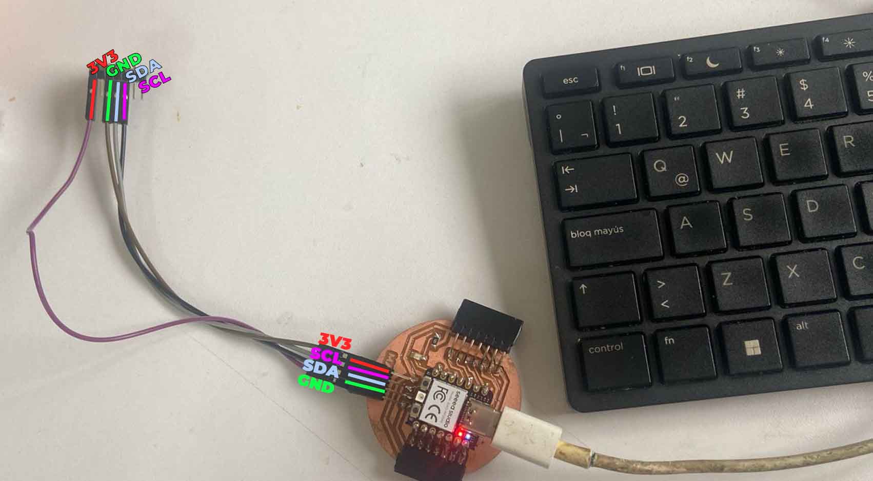
In order to program the time of flight distance, we have to have the I2C inputs, which are the SDA and SCL pins of the XIAO RP2040.
On board, these pins are located at the bottom so:
First we connect the VDD or 3v3 pin of the sensor with the connector that has 3V3, I used the purple colored cable.
Next I connected the GND pins of both the sensor and the development board. The wire color I chose was brown.
Then the SDA PIN that the sensor has with the SDA PIN on our development board and on the XIAO RP2040 it is PIN 6.
Then we connect the SCL pin of our sensor also to the development board. In the case of the XIAO RP2040 the SCL pin is PIN 7.
Now we will move on to programming with ARDUINO IDE. For this we have to install some libraries for programming.
#include Wire.h
        #include VL53L1X.h

        VL53L1X sensor;

        void setup() {
        Serial.begin(115200);
        Wire.begin();
        Wire.setClock(400000); // Use I2C at 400 kHz

        sensor.setTimeout(500);
        if (!sensor.init()) {
        Serial.println("Error detecting and initializing the sensor!");
        while (1);
        }

        // Use long distance mode and allow up to 50000 us (50 ms) for a measurement.
        // You can adjust these values to change the sensor's performance, but
        // the minimum measurement time is 20 ms for short distance mode and 33 ms for
        // medium and long distance modes. See the VL53L1X datasheet for more
        // information on range and timing limits.
        sensor.setDistanceMode(VL53L1X::Long);
        sensor.setMeasurementTimingBudget(50000);

        // Start continuous readings at a rate of one measurement every 50 ms (the
        // period between measurements). This period should be at least as long as the
        // timing budget.
        sensor.startContinuous(50);
        }

        void loop() {
        // Read distance in millimeters
        uint16_t distance_mm = sensor.read();

        // Convert millimeters to centimeters
        float distance_cm = distance_mm / 10.0;

        // Print the distance in centimeters
        Serial.print("Distance: ");
        Serial.print(distance_cm);
        Serial.println(" cm");

        // Wait for a second before the next reading
        delay(1000);
        }
The library is called Pololu as we can see in the picture. Here I leave the link to the page of Adrian Torres that helps you to do the programming, you can see if they have this component or other similar as it presents many more.
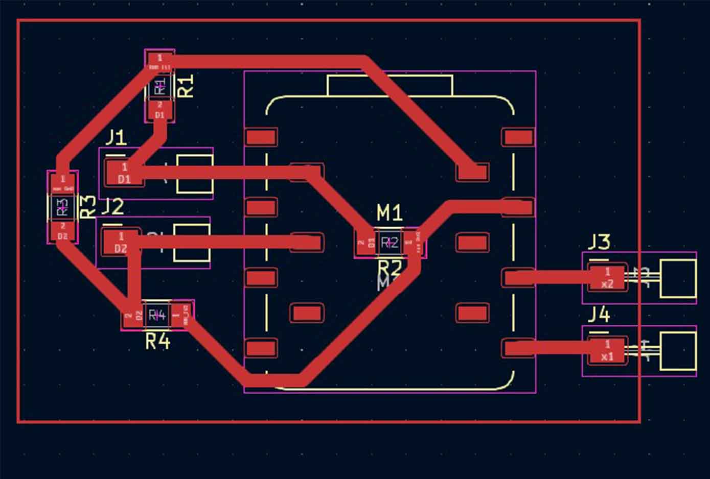
I decided to design a new board because the one I had did not allow me to perform responsive step tests, so I started by separating the comoonents but especially I was guided by the content of the assignment of the week.
We had a first approach to the KidCAD program to begin taking the first steps, I will detail how I started.
These are the steps to follow to be able to download the FAB lib and obtain the components, I leave the FILES here
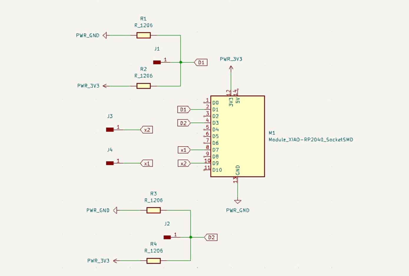
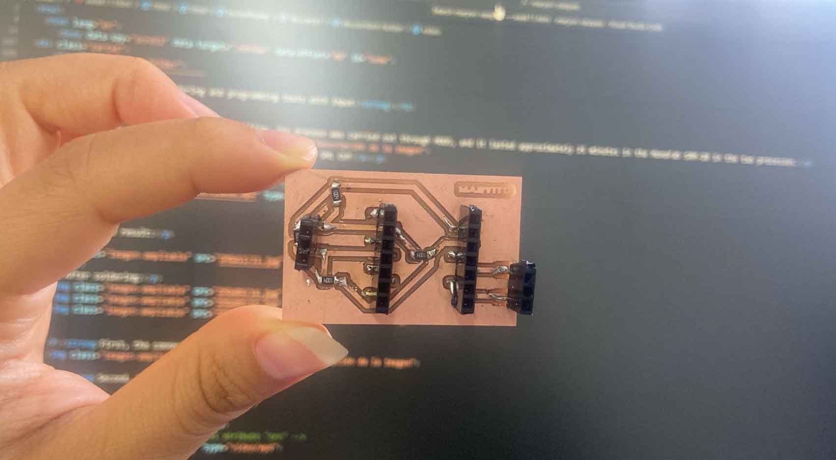
BOM and Schematic for Maryito
For the design, I used 4 x 1004 ohm resistors to go with the pins, plus 2 x 1x01 SMD header connectors, 2 x 1x07 SMD header connectors, and 2 x 1x07 SMD header connectors.
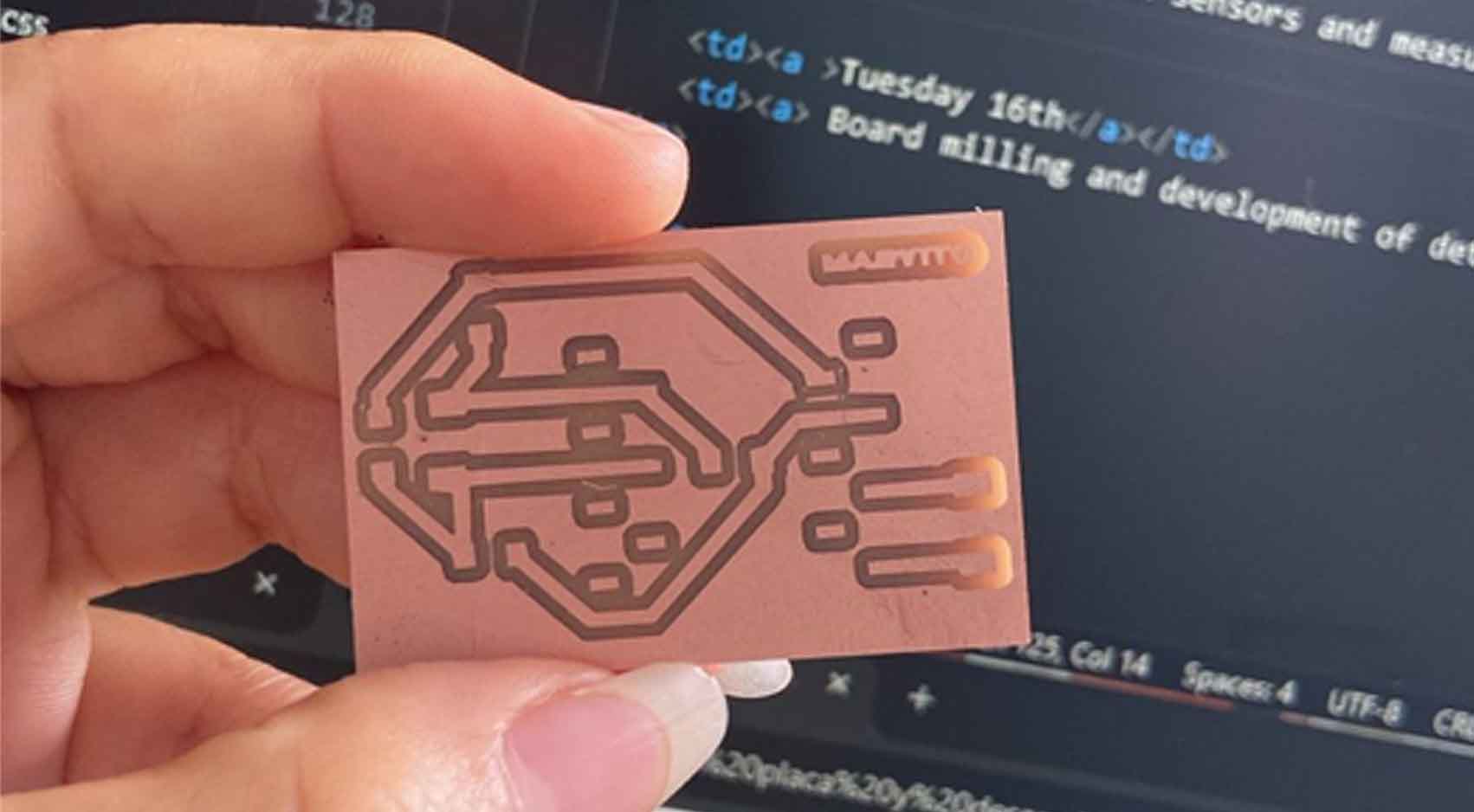
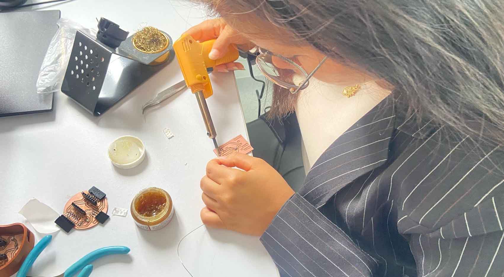
Having the traces and the cut for milling, the process was carried out through MODS, and it lasted approximately 10 minutes in the MonoFab SRM-20 in the two processes.
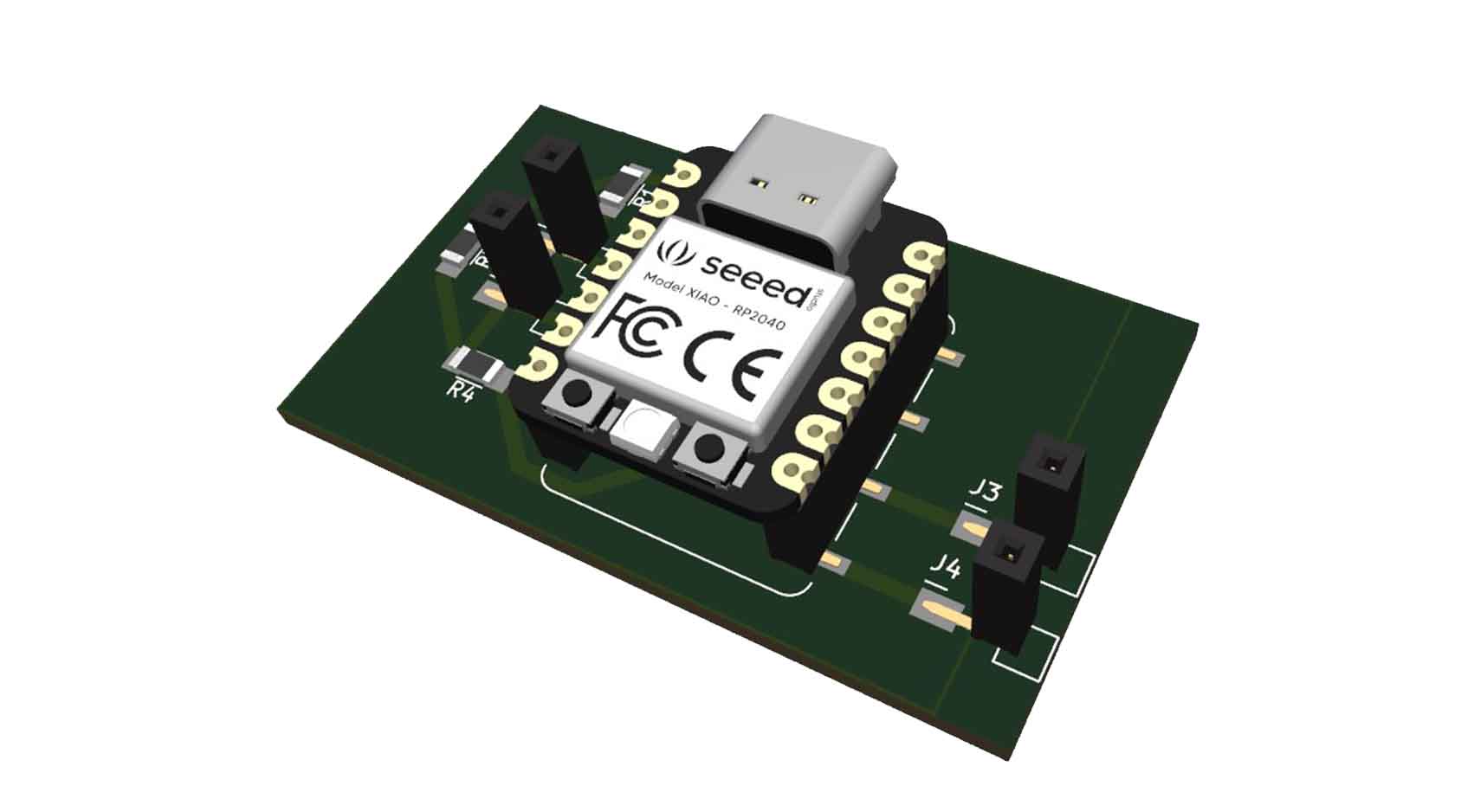
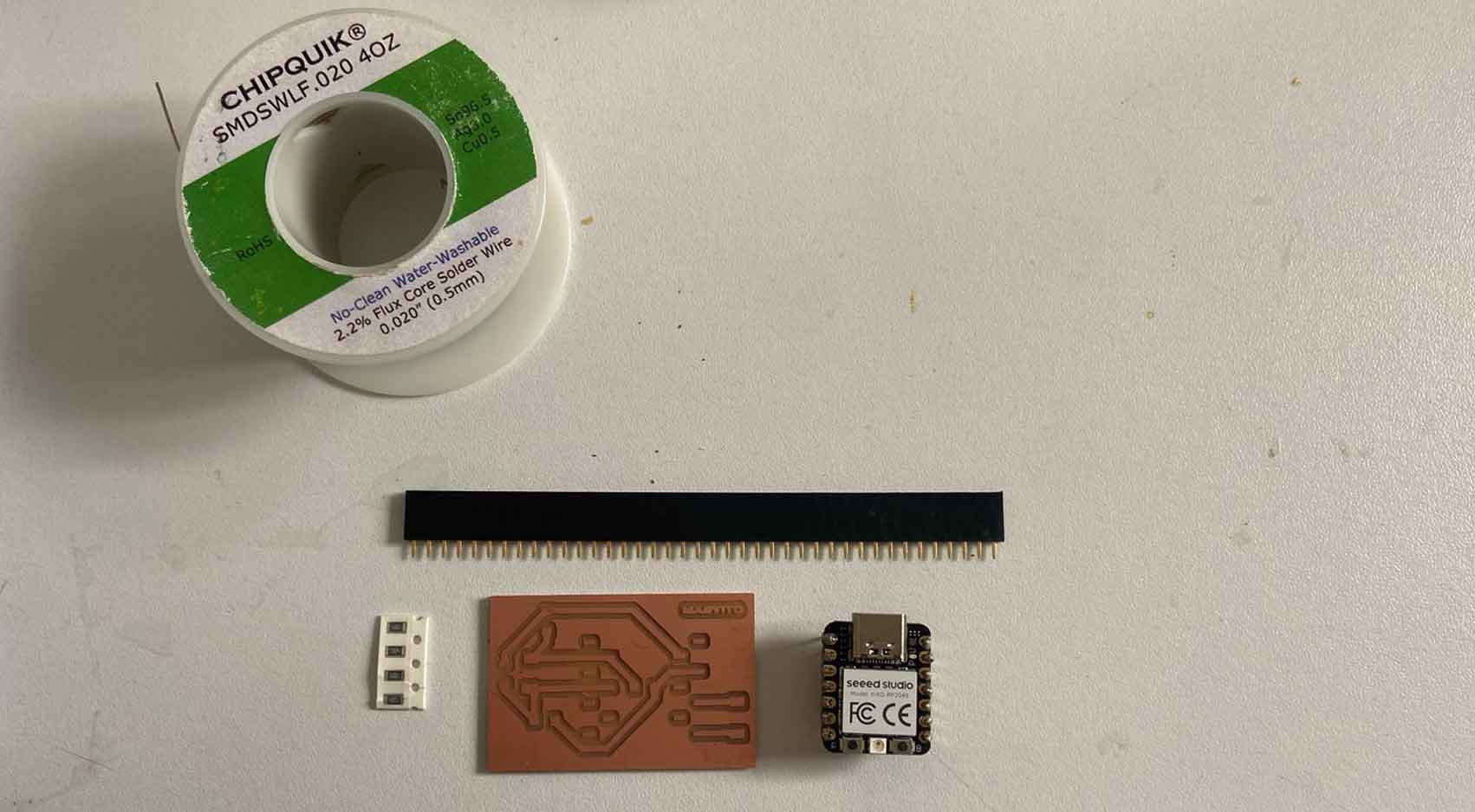
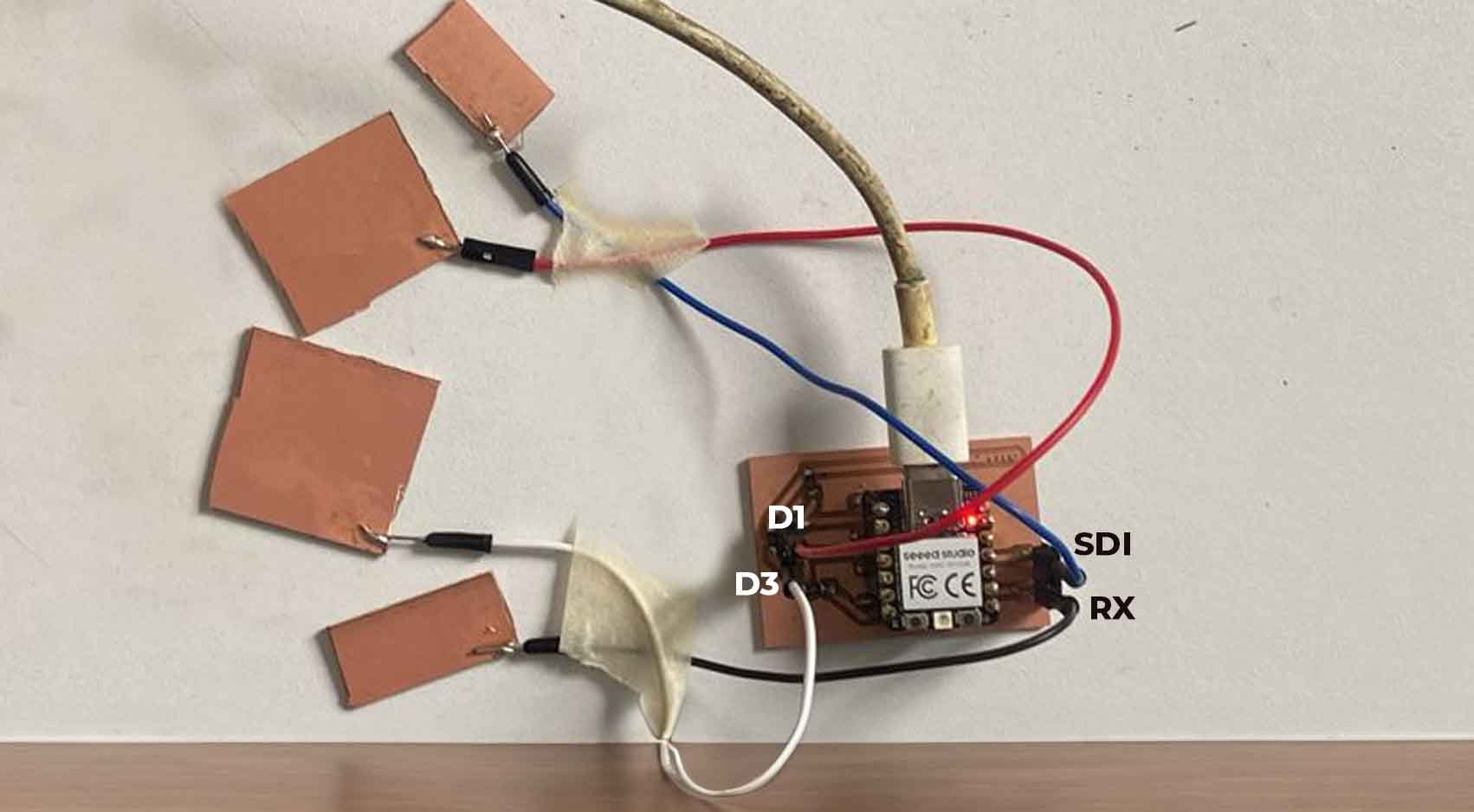
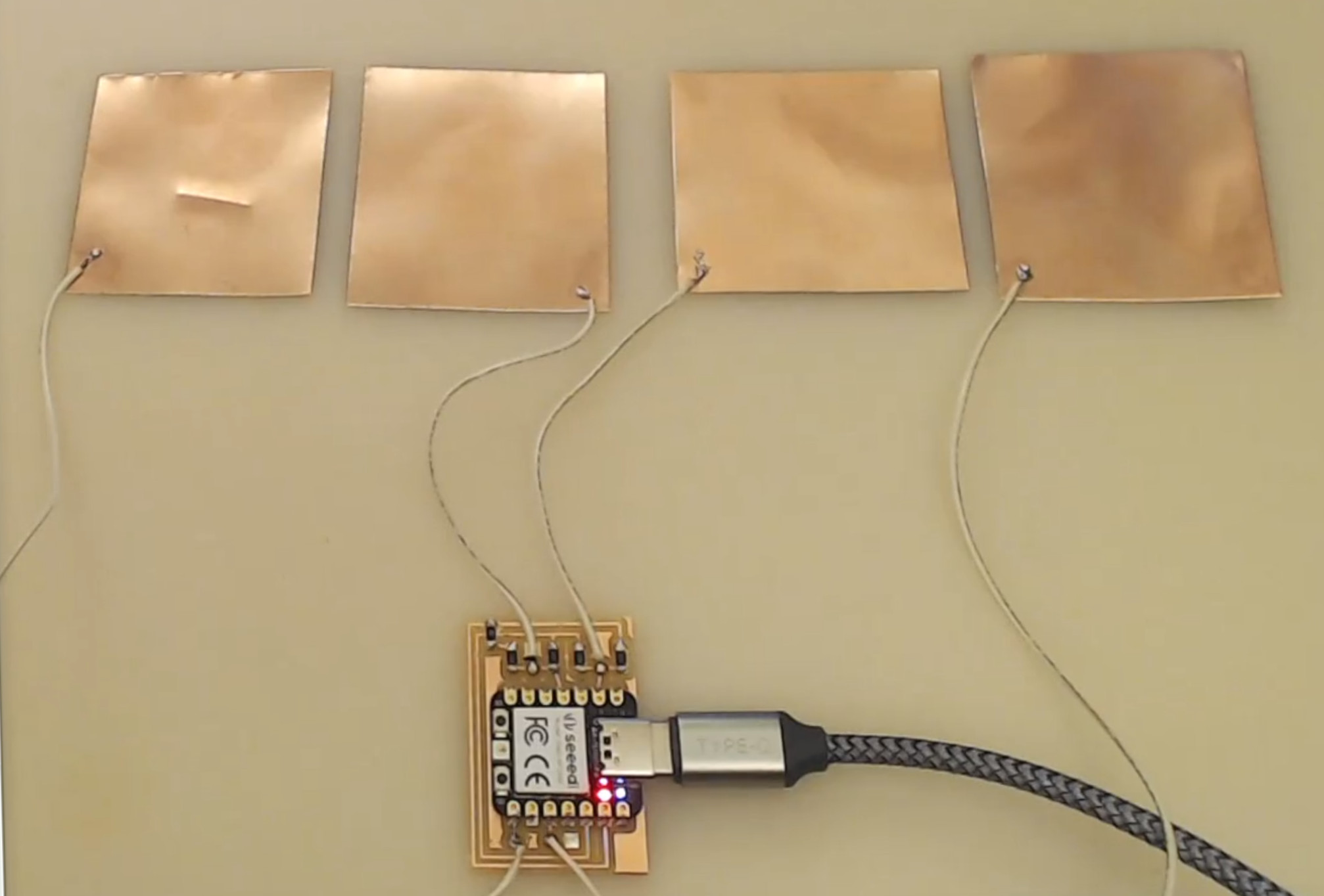
Then, using connector wires, we solder 4 copper plates preferably of equal size, these pick up the pressure signal and connect to the pins of the XIAO RP2040.
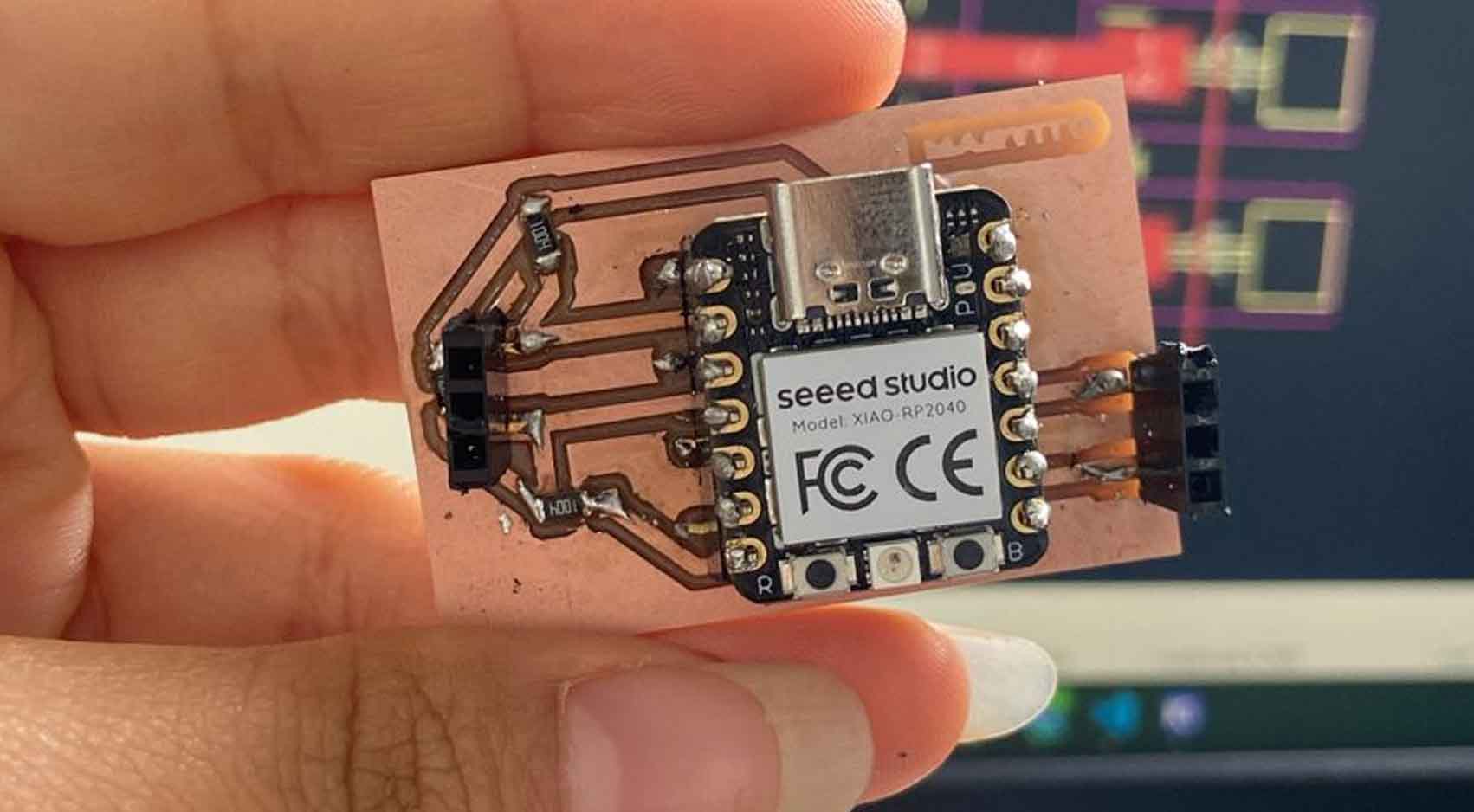
After carefully checking the connection with the multimeter to see if there is continuity in them, we connect the XIAO RP2040 to our pc, here is the ARDUINO code
After programming and reviewing each line in the programming, I was surprised how easy and fast we can get to this result so quickly.
Here is a video of the STEP RESPONSE moment with just a few small copper plates that receive the signal and the pressure level.
I was also able to measure the analog connections with the Oscilloscope, showing wave signals with spectrum, which means that the measurement is prolonged by the pressure exerted for several seconds.