Group Assignment
Take a look:
- Measure the power consumption of an output device
Individual Assignment
First
- Add an output device to a microcontroller board you've designed
Second
- Program it to do something
Group Assignment
Organization
Here is my organization to finish on time:
LINK TO THE ASSIGNMENT WEEKMEASURING CONSUMPTION POWER
We decided to measure the outputs of each of our personal boards, the purpose is to learn how to measure AMPS and VOLTS. In my case, I used the SERVO MOTOR Outputs and an OLED DISPLAY.
For this assignment I decided to improve my board, solving past mistakes, focusing more on the electronic considerations and functions than on the board design itself.
SERVO MOTOR
Torque: 1.2kg / cm @ 4.8v, 1.4kg / cm @ 6v
Weight: 10g
Spline Count:: 20T Gear Material: Plastic
Motor Type: Brushed
Speed: 0.12 / 60deg @ 4.8v, 0.10 / 60deg @ 6v
Voltage: 4.8
Plug v ~ 6v : JR
MORE ABOUT THE SERVO
VOLTAGE
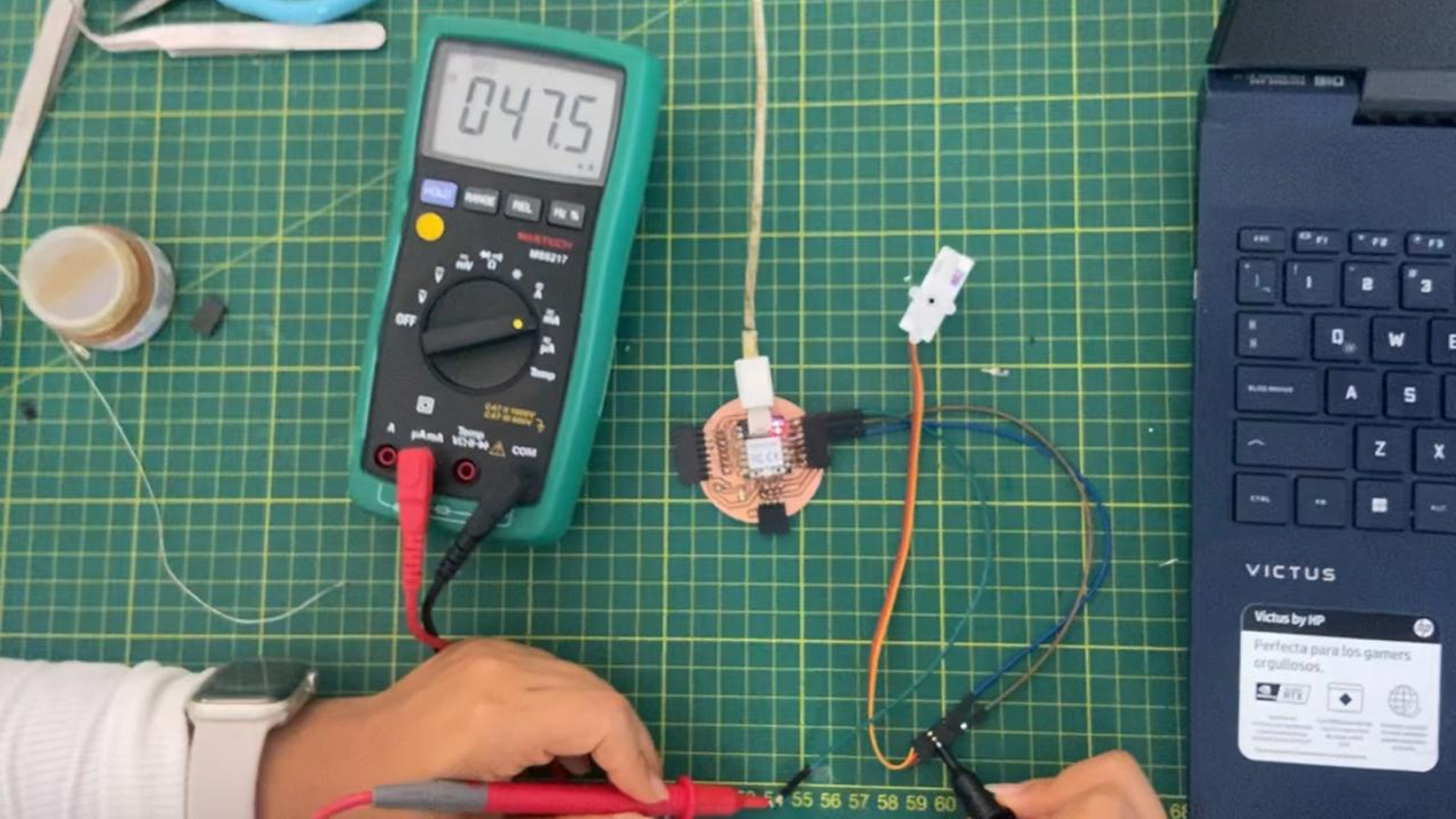
First we measure the VOLTAGE that the SERVOMOTOR needs for its operation, for this we place the COM of the multimeter on the GND of the SERVOMOTOR and the POSITIVE on the 5V of the MOTOR. This will give us a measurement of 4.65 to 4.68 of the voltage that the SERVOMOTOR needs to work. Here are some pictures of how we measure it.
In the video we can see the voltage change that the SERVOMOTOR has when turning or changing degrees. We must correctly place the COM and VOLTAGE points to be able to measure accurately.

AMPS
Now we are going to measure the amperes or intensity of the SERVOMOTOR. For this we need to make a SERIAL connection, where the COM and mA is connected to another point of the 5V, making a bridge. Then we will measure in mA and here the result.
Like the voltages, the amperage of the servomotor changes according to the movement made by the output and we can see the different values we get.
Once we have obtained the values of VOLTAGES (V) and CURRENT (mA), we can calculate the consumption of the SERVOMOTOR using this formula: WATTS = VOLTAGE (V) X CURRENT (mA).
THE SERVOMOTOR CONSUMES 0.14 WATTS
OSCILLOSCOPE
About continuity, from here we test with our Quentorres, fixing a point of the milled copper channel and another on the soldering of one of the pins of our board, the multimeter should make a sound when finding continuity, I leave evidence of the case

All correct with the tracks and their continuity, the plate does not short-circuit.
In the following video, we can see the behavior of the OSCILLOSCOPE when we contact the GND and see the data it gives us.
OLED DISPLAY
Operating voltage: 3V - 5.5V DC
Driver: SSD1306
Resolution: 128*64 pixels
Monochrome: white pixels (black background)
Viewing angle: 160°.
Visible area (display): 23*11.5 mm
Ultra-low power consumption: 0.08W (when all pixels are on)
Working Temperature: -30ºC ~ 70ºC
Dimension: 27*27*4.1mm
Weight: 5 grams
MORE ABOUT THE OLED DISPLAY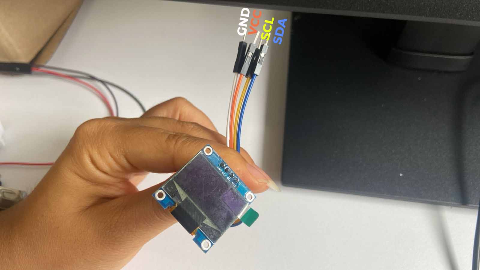
VOLTAGE
With the multimeter we measure the voltages of a Display. To do this we have to place the COM point of the multimeter in the GND and the mA point in the 3.3V point, both of the OLED. Here we can see how when connecting we obtain the voltage that the OLED receives and that it has for its operation.
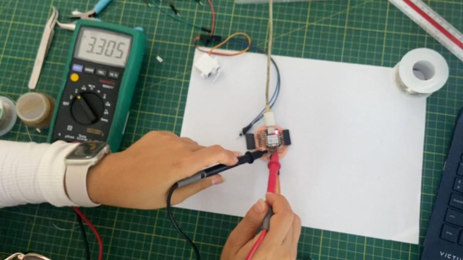
Here I show you a video of how we test with the multimeter. We can see that the value reaches the 3.3V that the OLED needs for its operation.
OSCILLOSCOPE
Now we will use the oscilloscope for the OLED. In this case, we did the tests on each pin of the OLED and it gave us the same wave signal as in the previous OUTPUT, only the intensity varies. Here the test:
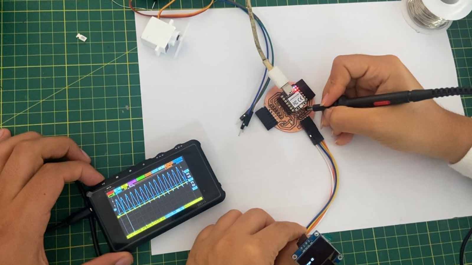
Here is a test video of how we used the oscilloscope on the OLED.
Individual Assignment
What am I going to do?
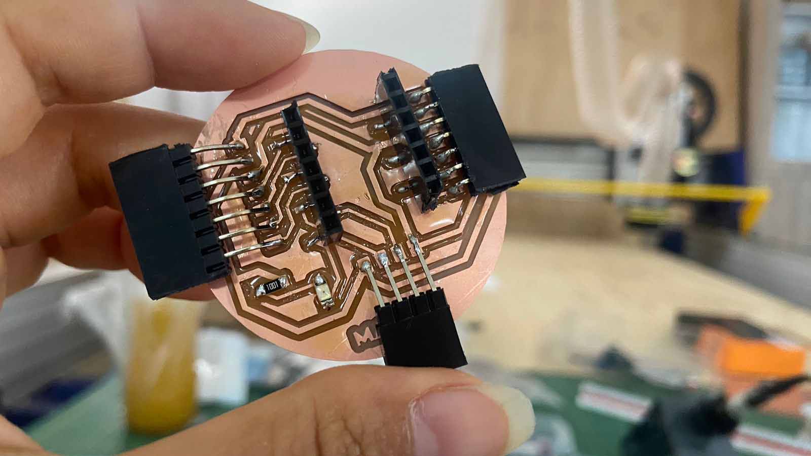
Last week's board (Man-go!) had some failures, first it could not turn on the display, despite using the correct pins for power, therefore, I set out this week to design a new board, with the ability to add 3 outputs.
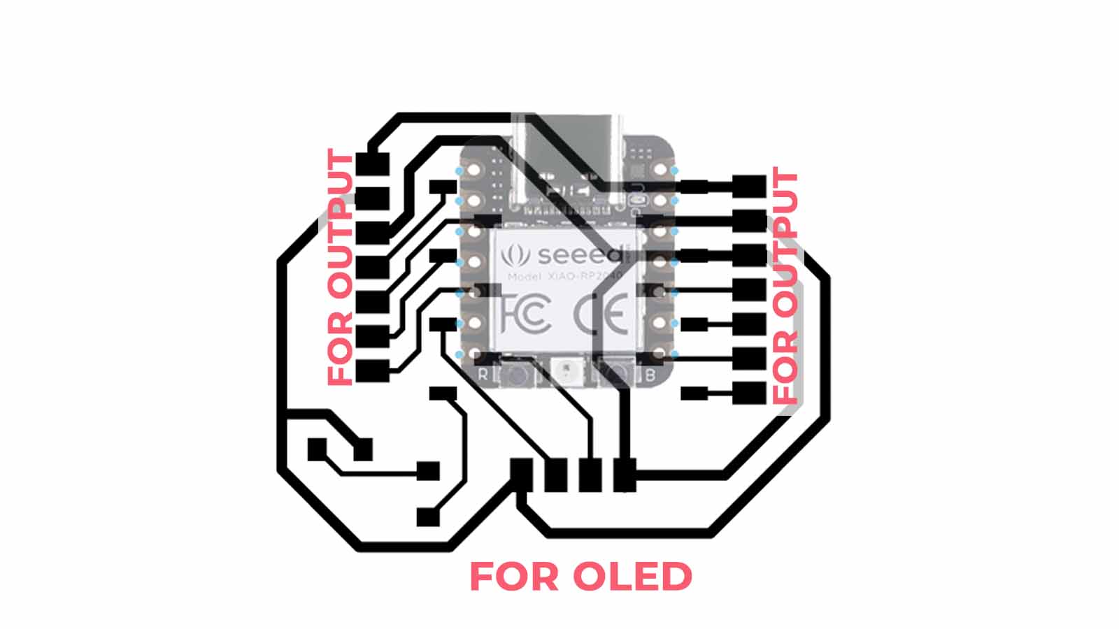
I also added an LED to indicate if the board is receiving a signal or working correctly, so I embedded the design in a circle to make it more compact.
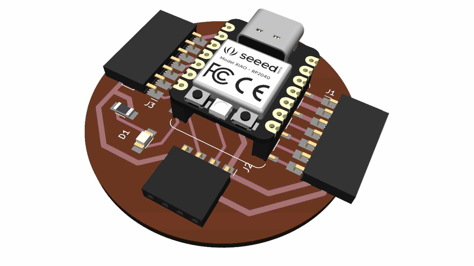
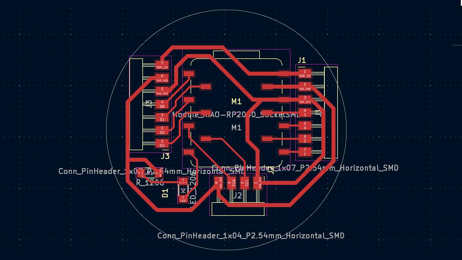
1. PCB design, ready!
We had a first approach to the KidCAD program to begin taking the first steps, I will detail how I started.
These are the steps to follow to be able to download the FAB lib and obtain the components, I leave the FILES here
BOM and Schematic for Maryo
Maryo |
Where to buy? | Amount |
| Seeed Studio XIAO RP2040 | Seeed Studio | 1 |
| 1kΩ resistor | Digikey | 4 |
| LED | Digikey | 4 |
| Male 4 row vertical header | Digikey | 5 |
ALL THE FILES HERE
2. Soldering and programming tests with Output
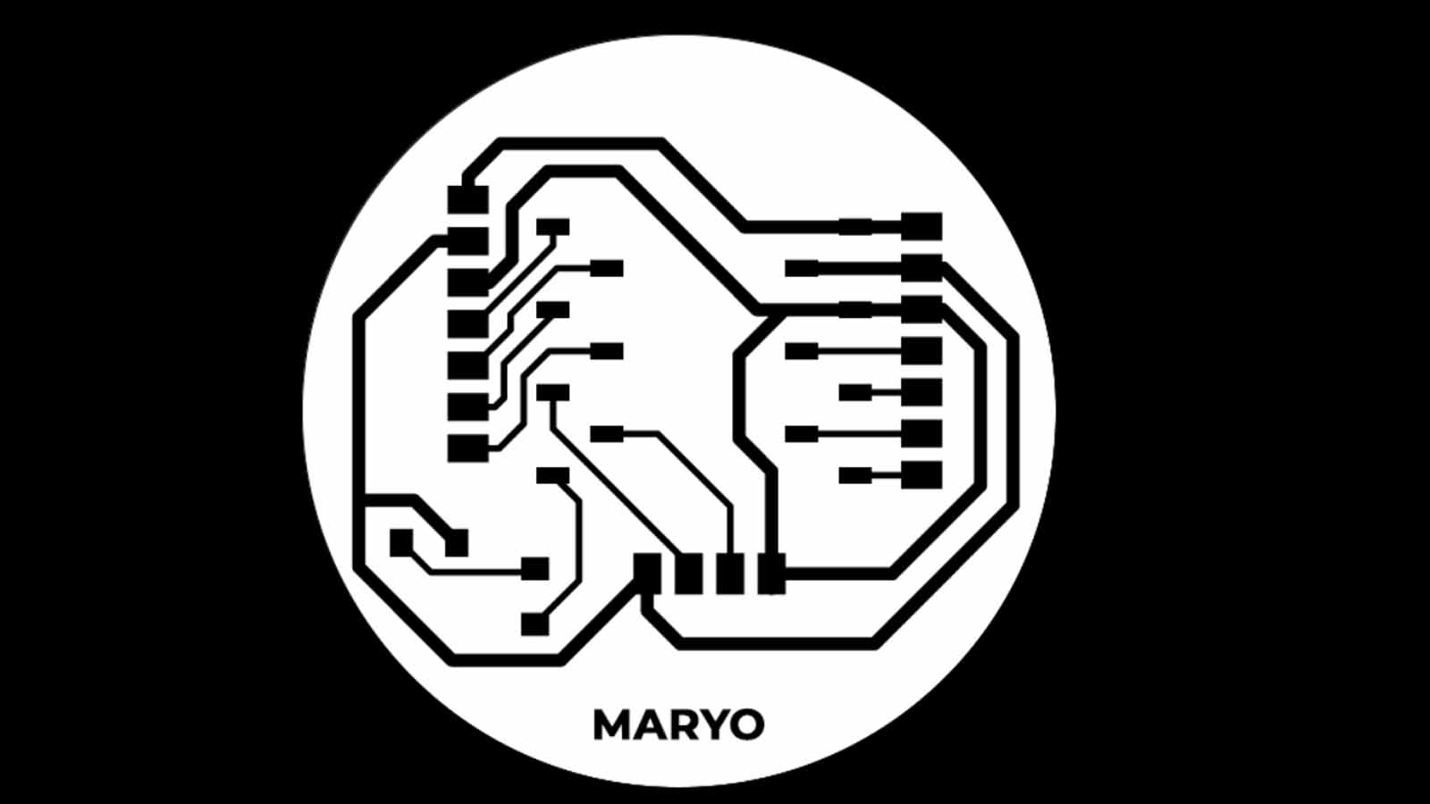
Plate milling
Having the traces and the cut for milling, the process was carried out through MODS, and it lasted approximately 25 minutes in the MonoFab SRM-20 in the two processes.
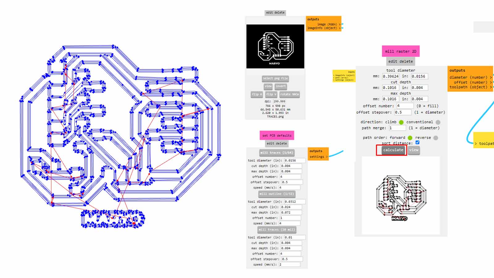
This's the result:
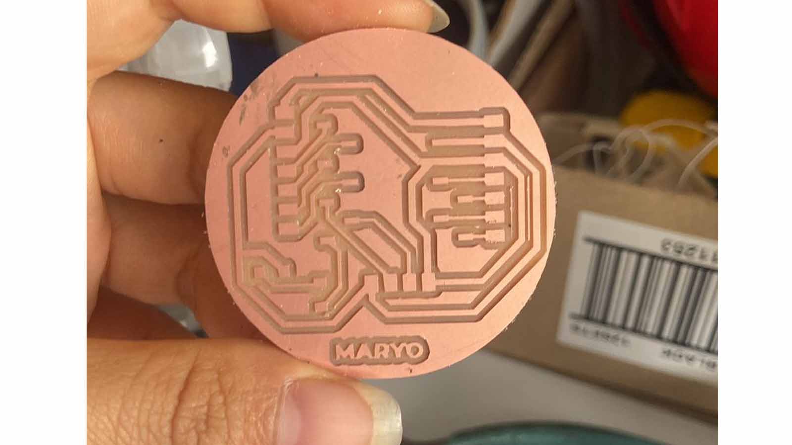
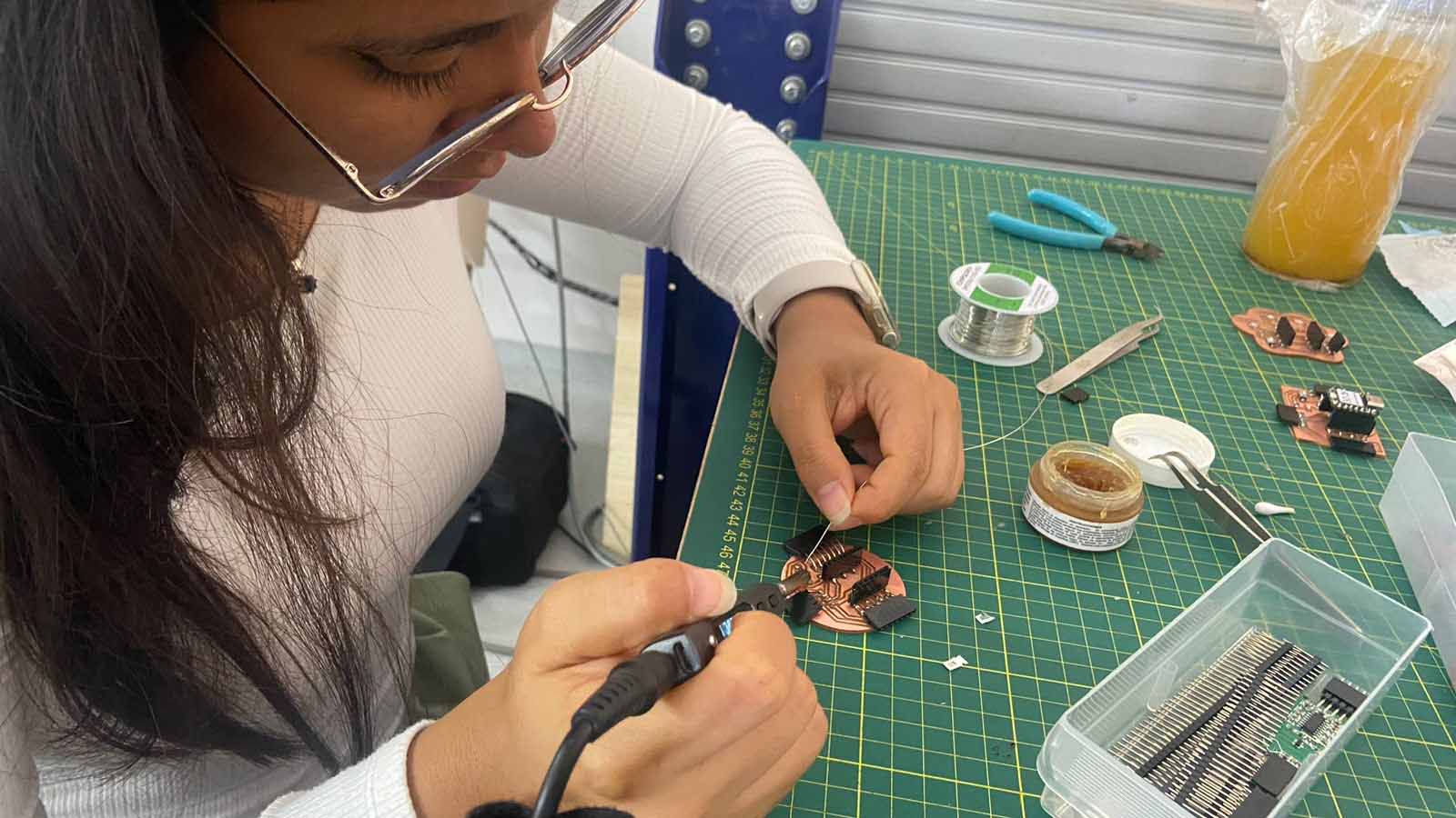
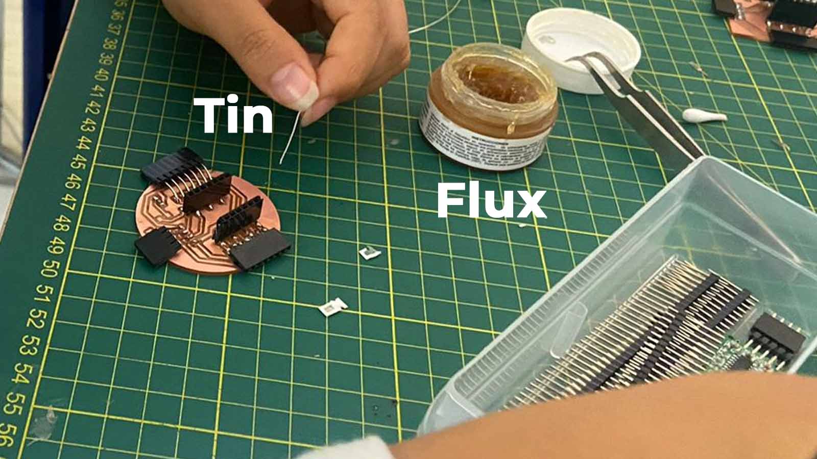
After soldering:
Display
Using the following code and connecting the pins thanks to a reference indicated by Chat GPT, I managed to turn on the Display, it is important to mention that it is important to download in the ARDUINO IDE the Adafruit_SSD1306 library from where we can configure the default power on the Display.
GND (Ground): connect it to the GND (ground) pin of the XIAO RP2040 board.
VCC (Power): Connect it to the 3.3V power pin of the XIAO RP2040 board. This pin will provide the power needed to operate the display.
SCL (Serial Clock Line): This is the clock pin for I2C communication. Connect it to the SCL pin (pin 5) on the XIAO RP2040 board.
SDA (Serial Data Line): This is the data pin for I2C communication. Connect it to the SDA pin (pin 4) on the XIAO RP2040 board.
In the library you use to control the display via I2C, there will likely be a function to enable the RP2040's internal pull-up resistors. For example, in the Arduino Wire library, you can call Wire.begin() to initialize the I2C communication, and this will automatically enable the RP2040's internal pull-up resistors.
I leave the code here
                #include Wire.h
                #include Adafruit_GFX.h.
                #include Adafruit_SSD1306.h

                #define SCREEN_WIDTH 128 // Ancho del display OLED en píxeles
                #define SCREEN_HEIGHT 64 // Alto del display OLED en píxeles

                // Dirección I2C del display OLED
                #define OLED_ADDR   0x3C

                // Declaramos el objeto de la clase Adafruit_SSD1306
                Adafruit_SSD1306 display(SCREEN_WIDTH, SCREEN_HEIGHT, &Wire);

                void setup() {
                    // Inicializamos la comunicación I2C
                     Wire.begin();

                    // Inicializamos el display OLED con la dirección I2C y el tamaño del display
                      if(!display.begin(SSD1306_SWITCHCAPVCC, OLED_ADDR)) {
                        Serial.println(F("No se pudo inicializar el display OLED con la dirección I2C"));
                        while (true);
                      }

                      // Limpiamos el buffer del display
                      display.clearDisplay();

                      // Escribimos un texto en el display
                      display.setTextSize(1);      // Tamaño del texto
                      display.setTextColor(SSD1306_WHITE); // Color del texto
                      display.setCursor(0,0);      // Posición del cursor
                      display.println("¡Hola, Mundo!"); // Texto a mostrar
                      display.display(); // Mostramos el texto en el display
                    }

                    void loop() {
                      // Nada más se ejecutará en el loop
                    }
A short explanation of the code:
       #include Wire.h
       #include Adafruit_GFX.h
       #include Adafruit_SSD1306.h
#include Wire.h: Includes the Wire library for I2C communication.
#include Adafruit_GFX.h: Includes the Adafruit GFX library, which provides basic graphics functions.
#include Adafruit_SSD1306.h: Includes the specific library to drive the SSD1306 OLED displays.
        #define SCREEN_WIDTH 128 // Ancho del display OLED en píxeles
        #define SCREEN_HEIGHT 64 // Alto del display OLED en píxeles

        #define OLED_ADDR 0x3C // Dirección I2C del display OLED
These directives define the width and height of the OLED screen in pixels and the I2C address (0x3C) of the display.
Adafruit_SSD1306 display(SCREEN_WIDTH, SCREEN_HEIGHT, &Wire);
A display object of class Adafruit_SSD1306 with the specified screen size and I2C communication is declared.
        void setup() {
            Wire.begin(); // Inicializamos la comunicación I2C

            if(!display.begin(SSD1306_SWITCHCAPVCC, OLED_ADDR)) {
              Serial.println(F("No se pudo inicializar el display OLED con la dirección I2C"));
              while (true); // Si no se puede inicializar, detener el programa
            }

            display.clearDisplay(); // Limpiamos el buffer del display

            display.setTextSize(1); // Tamaño del texto
            display.setTextColor(SSD1306_WHITE); // Color del texto
            display.setCursor(0,0); // Posición del cursor
            display.println("¡Hola, Mundo!"); // Texto a mostrar
            display.display(); // Mostramos el texto en el display
          }
Wire.begin(); Initialises I2C communication.
display.begin(SSD1306_SWITCHCAPVCC, OLED_ADDR): Initialises the OLED display with the specified I2C address. If it fails, prints a message on the serial port and stops the program.
display.clearDisplay(); : Clears the screen buffer, preparing it to display new content.
display.setTextSize(1);: Sets the text size to 1 (the smallest size).
display.setTextColor(SSD1306_WHITE); : Sets the text colour to white.
display.setCursor(0,0); : Sets the initial position of the cursor at the top left of the screen.
display.println("Hello, World!"); : Writes "Hello, World!" to the display buffer.
display.display(); : Sends the contents of the buffer to the screen for display.
        void loop() {
        // Nada más se ejecutará en el loop
         }
The loop function is empty, which means that no additional operations are continuously performed after the initial configuration.
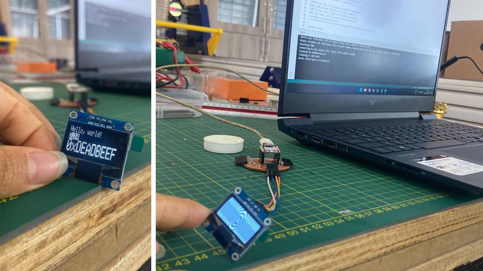
Here are some messages on the Display:
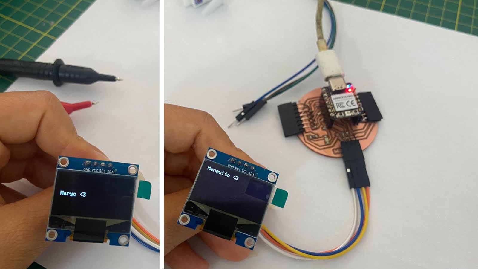
I leave here the ARDUINO sketch and a video test of its operation.
Servo-Motor
For the Servo motor, I requested the code to Chat GPT for the operation, it should be noted that the first code was for slow motion, after some adjustments I could make it faster, I leave the code here
                #include Servo.h

                Servo myservo; // Create a Servo object to control the servo motor

                #define SERVO_PIN 3 // Pin to which the servo is connected

                void setup() {
                myservo.attach(SERVO_PIN); // Assign the pin to the servo object
                }

                void loop() {
                // Move the servo motor to the 0 degree position
                myservo.write(0);
                delay(1000);

                // Move the servo motor to the 90 degree position
                myservo.write(90);
                delay(1000);

                // Move the servo motor to the 180 degree position
                myservo.write(180);
                delay(1000);
                }
Explanation of the code
#include Servo.h
This line includes the Servo library, which provides functions to control servo motors.
Servo myservo;
This line creates a Servo object named myservo that will be used to control the servo motor.
#define SERVO_PIN 3
This line defines a constant named SERVO_PIN with a value of 3. This indicates that the servo motor is connected to pin 3 of the Arduino.
void setup() {
            myservo.attach(SERVO_PIN);
          }
The setup function runs once when the program starts. Inside this function, the attach method is called on the myservo object, which attaches the servo motor to the pin defined by SERVO_PIN.
            void loop() {
                myservo.write(0);
                delay(1000);

                myservo.write(90);
                delay(1000);

                myservo.write(180);
                delay(1000);
              }
The loop function runs repeatedly. Inside this function:
- The servo motor is moved to the 0-degree position with myservo.write(0);.
- The delay(1000); function pauses the program for 1 second.
- The servo motor is then moved to the 90-degree position with myservo.write(90);.
- Another 1-second pause occurs with delay(1000);.
- Finally, the servo motor is moved to the 180-degree position with myservo.write(180);.
- The program pauses again for 1 second before repeating the process.
I leave here a video test of its operation.