Scroll to Top
CAD

Computer-Controlled Cutting


Group Assignment

  • 1. Characterize your lasercutter's focus, power, speed, rate, kerf, joint clearance and types

Individual Assignment

  • 1. Cut something on the vinylcutter

  • 2. Design, lasercut, and document a parametric construction kit, accounting for the lasercutter kerf, which can be assembled in multiple ways, and for extra credit include elements that aren't flat

Group Assignment


Click here: Characterizing the lasercutter's focus, power, speed, rate, kerf, joint clearance and types


Vinyl Cutting


Vinyl cutting stands out as an intriguing process, allowing us to precisely cut any 2D images or vectors into vinyl using a computer-controlled CNC machine equipped with a customizable pen knife.


Roland GX-24 Vinyl cutter machine

In the lab, we utilize a specific type of vinyl cutting machine. When discussing vinyl cutting machines, there are primarily two types: active and passive. In an active machine, the cutting blade's rotations are controlled by a servo mechanism. On the other hand, in a passive machine, the technology resembles that of a roller coaster tire. When the entire head moves across a plane, the blade turns accordingly. The Roland GX-24 exemplifies a passive blade type machine. More details here.

Project Management
Project Management


  1. Begin by activating the machine and placing the material to be cut onto it. Whether it's a Roll, Piece, or an edge, ensure that the rollers securely grip the sheet. Proper gripping is indicated when the material aligns with the white markers. Without this alignment, the machine will not initiate. Identify the type of material being used, whether it's a sheet, edge, or roll. Use the arrow keys to position the sheet appropriately. To determine the ideal cutting force for the material, conduct test cuts by pressing and holding the "Test" button.
  2. Project Management
  3. A successful cut is characterized by the outer circle peeling off cleanly without affecting the inner rectangle like in the figure above. This outcome signifies the perfect cutting force. For instance, in the case of vinyl, the optimal cutting force was found to be 110gf.
  4. Project Management
  5. Set the origin for cutting.
  6. Project Management
  7. Different blades available
  8. Project Management


Designing with Inkscape

Inkscape is a freely available and open-source software tool designed for creating vector graphics. Its primary function is to generate images in the Scalable Vector Graphics (SVG) format. However, it also supports importing and exporting various other file formats, enhancing its versatility and compatibility with different design applications.


  1. First, I used the logo I created duing the previous week (refer here).

  2. Next, I used bitmap trace and vectorized some images of swimming, roblox and Fab Foundation.
  3. Project Management


Fab Mods

Mods is a modular digital manufacturing CAM (Computer-Aided Manufacturing) software that is open-source and developed by MIT’s Center for Bits and Atoms (CBA). This software allows for the unified control of various machines directly from a computer. It facilitates communication with a range of manufacturing equipment including laser cutters, vinyl cutters, and CNC mills, making it a versatile tool for digital fabrication processes..


  1. The subsequent step involves initiating Fab Mods locally due to issues with the online USB port of the machine. To commence locally, navigate to the Fab Mods directory in the terminal and execute the "start-servers" file using the following command:

  2. 
      bash start-servers  
                                

    Project Management

  3. Next, I followed these steps. So, right-click on the screen>programs>open program and this page appears, from this choose cut under Roland GX-GS 24 vinyl cutters
  4. Project Management

  5. Choose the appropriate program compatible with the machine and import the image file in either .png or .svg format. Adjust the size of the image solely by modifying the DPI (dots per inch) setting. Once all settings are confirmed suitable, proceed to initiate the calculation process. Transmit the calculated data to the machine using the USB port interface.
  6. Project Management

  7. The cutting process

  8. So, I've cut in red, blue and green. The cuts can be seen if observed correctly.
  9. Project Management

  10. Remove and apply to a surface using a transfer sheet. In our case, which is a masking tape. When applying multiple layers on each other use tweezers for good precision.
    Project Management
    I gave my sister swimming stickers, while I decided to keep the Fab Foundation Logo for myself. However, my laptop was already covered in stickers. To accommodate the new addition, I placed it on top of an existing sticker, making it somewhat obscured from view.
  11. Project Management
  12. This is how my sister stuck the stickers I gave her. This is not how I imagined it but it is what it is.
  13. Project Management


Laser Cutting


Laser cutting is a thermal cutting process that employs a concentrated laser beam within the cutting area to melt the material. Subsequently, a gas or air is utilized to expel the molten material, resulting in the desired cut.


Laser Cutting Machines

In our FAB LAB, we have two different types of Laser cutting machines. One is the Trotec Speedy100, which is primarily used for the FAB academy and is capable of cutting materials like acrylic, wood, and cardboard. The other machine is the Trotec Speedy400, which is part of the Super Fab Lab. This machine is specifically designed for engraving circuits to create PCBs. Both machines are manufactured by Trotec, with the Speedy400 being slightly more powerful than the Speedy100.


We encountered an issue with the first machine, the Trotec Speedy100, which is currently out of operation. Consequently, we've been utilizing the second machine, the Trotec Speedy400, for engraving purposes. The cutting part was out of operation. More details are available here

Project Management

Focusing methods


Automatic Focus: Sonar Technology TM (automatic focusing with ultrasonic sensor), ensure the ultrasonic sensor is clean. Choose the appropriate lens in the software settings. Position the laser pointer onto the workpiece surface for focusing. Press both keys of the Z-axis control button to move the table to the focus position, aligning the laser beam. With focus achieved, commence laser processing.


Focus tool: position the processing head using the X/Y Laser head control buttons. Hang the focus tool on the laser head. Adjust the working table upwards with the Z-axis button, avoiding collisions. Elevate slowly, tapping the Z-axis button to ensure the focus tool's alignment before it reaches the material surface.


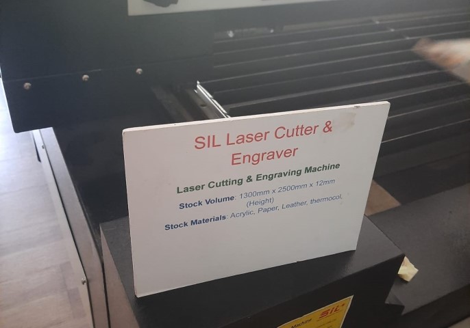
Additionally, we've been utilizing the SIL Laser Cutter and Engraver for both engraving tasks and group assignment. However, this is an open machine and the pungent smell, makes it very difficult to use the machine.

Project Management
Project Management


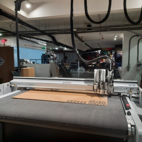
ZUND G3 L-2500 Digital Cutter

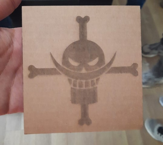
A Zund cutting machine represents a digital cutting system utilized for cutting a diverse range of materials including paper, cardboard, textiles, and plastics. This machine employs a computer-controlled cutting head capable of movement along multiple axes, enabling it to execute precise and intricate cuts. Zund cutting machines are available in several models, each offering distinct cutting capabilities such as cutting, creasing, and routing.

Project Management

  1. To initiate cutting using a DXF file format, begin by accessing the cut editor. Navigate to the file menu and select "Add job" to incorporate the desired file for cutting.
  2. Project Management
  3. Next, proceed to optimize the spacing between individual sketches. To achieve this, press the space key and manipulate the geometry as necessary. Additionally, select all figures and navigate to "Objects" followed by "Numerical Geometry." Here, offset the X and Y axes from the origin to establish an initial clearance before the cutting process commences.
  4. Project Management
  5. To optimize the design, either press "O" or navigate to "Tools" and select "Optimize." Confirm the optimization by clicking "OK." Starting from the rightmost corner, define the type of operation required. Choose from a variety of operations such as creasing or cutting. After selection, specify the material to be used for cutting from the options available in the right-hand corner. The machine features a scanner that automatically scans the bed and locates the corners of the inserted sheet. Alternatively, manual adjustment is possible. While creating a Job register is not mandatory, it can significantly reduce manual effort. To create one, add another step and select "Register." Choose the desired starting cutting position. Ensure the register process occurs first by moving up the job using the arrow mark. Activate the job and close the application. Then, navigate to the Soft Cut Queue where the activated job will be visible. Double-click the job to open job settings.
  6. Project Management
  7. In the job settings, select the appropriate tool and adjust the base depth to ensure the sheet is cut through without affecting the bed.
  8. Project Management
  9. Set the starting point for the Zund to cut. Once all settings are confirmed, start the job.
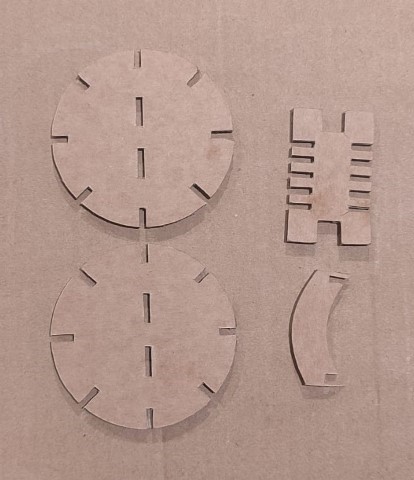
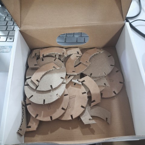
  10. Project Management
  11. Cutting process


Parametric Construction Kit


Parametric Modelling

In Fusion 360, parametric modeling enables precise design through parameters and constraints. Users define dimensions and relationships, maintaining associativity for easy modification. Design history records operations, facilitating iterative changes. Design parameters offer flexibility for exploring design variations efficiently, making Fusion 360 a powerful tool for 3D modeling.


  1. I added dimensions i.e. width and height to define the size of my rectangle. This step helped make my design adjustable later on.
  2. Project Management
  3. I created a 2D sketch on a plane of a rectangle and added the defined parameters as dimensions.
  4. Project Management
  5. Once my sketch was ready, I used the extrude command to turn it into a 3D shape. I simply selected the sketch and pulled or pushed it to create the desired thickness which was defined as parameter.
  6. Project Management
  7. Next, I updated the values of my parameters and got the updated 3D model.
  8. Project Management
  9. To create female slot in the rectangle I took the 2D sketch again and drew a rectangle with defined parameters i.e (thickness+kerf) and length of the slot. Kerf was found during the group assignment. But here I just added a standard value of 0.24.
  10. Project Management
  11. Now I tried to create a hexagon with slots. So go to create>polygons>inscribed polygon and sketch a hexagon. To add slot, create a sketch of rectangle, give dimenisons and constraints so that the slot is at the appropiate position. Next, use circular pattern to repeat the slots on six sides of the hexagon.
  12. Project Management
  13. Extrude the sketch to get this.
  14. Project Management
  15. Duplicate the hexagon using move/copy and use align tool to select the centers of slots to be connected.
  16. Project Management
  17. To create a parametric construction in mutliple configurations, I used references for some inspiration. And now I started designing the parts for the kit using the previous steps.
  18. Project Management
  19. Here's all the parts.
  20. Project Management
  21. Next I arranged the parts.
  22. Project Management
  23. Then I saved it as a DXF file.
  24. Project Management
  25. Next I set up Zund for cutting. First attempt to gather the components. Some pieces weren't fitting.
  26. Project Management
  27. Ready to get started! After a few attempts to gather all the components, maneuvering around the bends in the cardboard, I'm finally set to begin building something out of them.
  28. Project Management
  29. First configuration
  30. Project Management

  31. Other configurations
  32. Project Management

References


Here are the designs I referred for designing my construction kit:

Design 1

Design 2

Design 3

Design Files