Write a program for a microcontroller development board that you made,
to interact (with local input &/or output devices)
and communicate (with remote wired or wireless devices)
Extra credit: use different languages &/or development environments
Extra credit: connect external components to the board
Group Assignment
Browse through the data sheet for your microcontroller
Compare the performance and development workflows for other architectures
Embedded programming refers to the process of writing software for embedded systems.
Embedded systems are specialized computing systems that are designed to perform specific functions within a larger system. Unlike general-purpose computers, embedded systems are typically dedicated to a particular task or set of tasks and are often built into a larger device or product.
Embedded programming involves writing code that controls the behavior of the embedded system. This code is typically written in languages such as C, C++, or sometimes assembly language, depending on the specific requirements of the system and the hardware it uses.
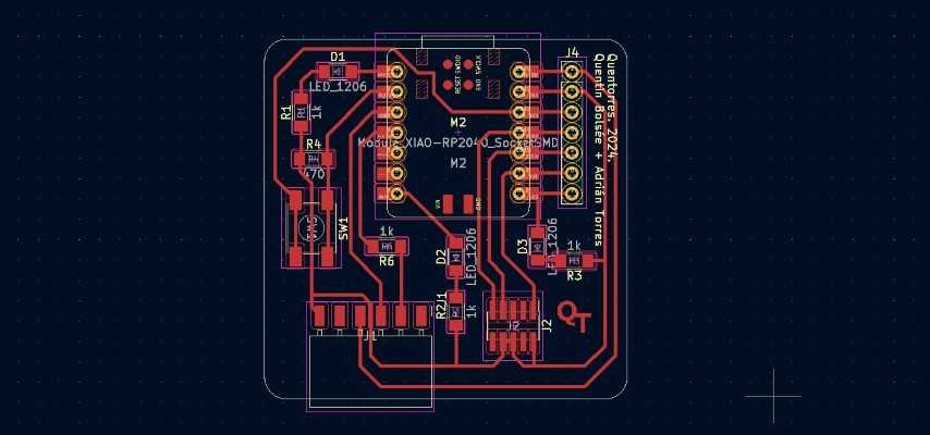
Quentorres Board
The Quentorres board, initially conceptualized by Quentin Bolsée, underwent a significant redesign spearheaded by Adrián Torres in 2024 during the Instructors Bootcamp held in León.
This revamped iteration of the board boasts versatility, specifically tailored for programming both AVR (Automatic Voltage Regulators) Series 1 and 2, along with ARM (Advanced RISC Machines) microcontrollers.
Equipped with fundamental input-output functionalities such as buttons and LEDs, it also incorporates breakout pins facilitating seamless integration with external components.
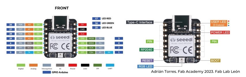
Seeed Studio XIAO RP2040
The Seeed Studio XIAO RP2040 is a compact development board powered by the RP2040 microcontroller.
With dual ARM Cortex-M0+ cores running at up to 133MHz, it offers ample processing power for embedded projects.
Featuring onboard USB-C connectivity for programming and power, it includes various I/O interfaces like digital, analog, PWM, UART, I2C, and SPI, facilitating versatile connectivity with external peripherals.
Arduino compatibility allows easy programming using the Arduino IDE, leveraging its extensive ecosystem and community support.
Despite its small size, the XIAO RP2040 provides expansion options through GPIO pins, making it suitable for diverse embedded applications with space constraints.
More details are available here.
Programming on microcontroller development board
During week four
I had already tested out programming on my PCB but since it is the embedded programming week, I'll start with the basics of programming.
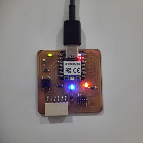
So, firstly after making sure all the libraries were properly installed, I loaded the blink program as shown below.
It worked correctly.
Button controlled LED ON/OFF
I tried to program the LED ON/OFF via the action of pressing the button. So referring the PCB diagram and datasheet of Seeed Xiao RP2040
I understood that the button is connected to pin 27 and the LEDs are connected to pin 26, 0 and 1.
To start, I tried to control the LED at pin 0 by pressing the button. Firstly, we need to understand the logic of the program.
So here's an algorithm to understand the flow of the code.
    1. Define BUTTON_PIN as pin 27 and LED_PIN as pin 0.
    2. Set up LED_PIN as an output and set up BUTTON_PIN as an input.
    3. If buttonState is HIGH, turn on the LED and If buttonState is LOW, turn off the LED.
    4. Repeat 3
Based on the algorithm, I tried to develop a program with my previous experience in coding.
    // Define the pin numbers
    #define BUTTON_PIN 1  // Pin D1
    #define LED_PIN 0     // Pin D0

    void setup() {
        // Initialize the LED pin as an output
        pinMode(LED_PIN, OUTPUT);
        // Initialize the button pin as an input with internal pull-up resistor enabled
        pinMode(BUTTON_PIN, INPUT_PULLUP);
    }

    void loop() {
        // Read the state of the button
        int buttonState = digitalRead(BUTTON_PIN);

        // If the button is pressed (buttonState is LOW)
        if (buttonState == LOW) {
        // Turn on the LED
        digitalWrite(LED_PIN, HIGH);
        } else {
        // Turn off the LED
        digitalWrite(LED_PIN, LOW);
        }
    }
Here's the output of the code:
Button controlled LED ON/OFF (with and without flag)
As you can see in the video, the LED only lights up when the button is pressed and is immediately off when the button is released.
But like in practical cases, the LED should stay in ON/OFF position when the button is pressed. So, I need to make some changes in the code and introduce a
variable to store the state of the LED. Here's the code:
    // Define the pin numbers
    #define BUTTON_PIN 27
    #define LED_PIN 0

    // Variable to store LED state
    bool ledState = false;

    void setup() {
    // Initialize the LED pin as an output
    pinMode(LED_PIN, OUTPUT);
    // Initialize the button pin as an input with internal pull-up resistor enabled
    pinMode(BUTTON_PIN, INPUT_PULLUP);
    }

    void loop() {
    // Read the state of the button
    int buttonState = digitalRead(BUTTON_PIN);

    // If the button is pressed (buttonState is LOW)
    if (buttonState == LOW) {
        // Toggle the LED state
        ledState = !ledState;
        // Update the LED accordingly
        digitalWrite(LED_PIN, ledState ? HIGH : LOW);
    }
    }
To simply this program without the state variable, I wrote a small algorithm to understand the flow of code and its logic.
    1. Define BUTTON_PIN as pin 27 and LED_PIN as pin 0.
    2. Set up LED_PIN as an output and set up BUTTON_PIN as an input.
    3. If the button is pressed, turn on led if it's off and turn off it’s on.
    4. Repeat 3
Based on the algorithm, here is the program written without flag/state variable.
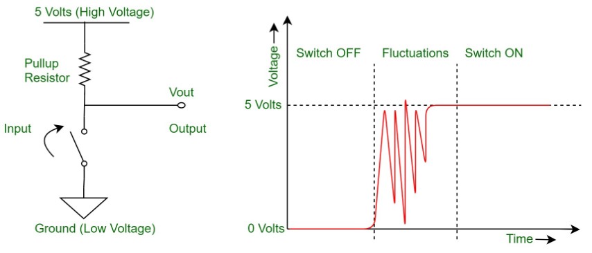
"Button bounce" refers to a phenomenon that occurs when a mechanical button or switch is pressed or released.
When a button is physically pressed or released, the metal contacts inside it make momentary but rapid electrical connections and disconnections.
This process can create multiple rapid transitions in the electrical signal instead of a single clean transition.
These rapid transitions, known as "bounces," can cause unreliable or erratic behavior in electronic circuits that are meant to respond to button presses.
As it can be seen in the video, pressing of the button doesnot alter the state of the LED effectively.
Sometimes it stays in its previous state without changing and this is due to bouncing effect. Also,
if we long press the button, the LED will also start to flicker. To recify that,
we need a debounce delay.
Button debouncing is a technique used in electronics to ensure reliable detection of button presses.
Debouncing involves smoothing out these transitions to provide a stable and accurate signal.
So here's the modified code:
    #define BUTTON_PIN 27
    #define LED_1 0

    void setup() {
        pinMode(LED_1, OUTPUT);
        pinMode(BUTTON_PIN, INPUT_PULLUP);

    }

    void loop() {

        int buttonState = digitalRead(BUTTON_PIN);
        if (buttonState == HIGH) {
            if ((digitalRead(LED_1) == HIGH) ) {
                digitalWrite(LED_1, LOW);

            }
            else {
                digitalWrite(LED_1, HIGH);

            }
            while(digitalRead(BUTTON_PIN) == HIGH); //wait until the button is released
            delay(50); //debounce delay
        }
    }
I tried to implement the same to all three LEDs. Here's the modified code:
In Arduino IDE, serial communication refers to the process of sending and receiving data between an Arduino board and a connected computer or another device via a serial interface.
The Serial Monitor is a built-in tool in Arduino IDE that allows users to view and interact with the data being transmitted through serial communication.
Baud rate refers to the rate at which data is transmitted over the serial connection, measured in bits per second (bps)
Serial Communication in Arduino IDE: Arduino boards typically have one or more hardware serial ports that can be used for serial communication.
The most commonly used serial port is Serial, which communicates via the USB connection to the computer running the Arduino IDE.
Users can also use SoftwareSerial library to create additional software-based serial ports on other digital pins.
Serial Monitor: The Serial Monitor tool in Arduino IDE allows users to monitor and interact with the data being sent and received over the serial port.
It displays the data in text format, enabling users to debug and analyze their Arduino sketches by observing the output of print statements or other serial communication commands.
Baud Rate: When establishing serial communication between an Arduino board and a computer or another device, both devices must use the same baud rate.
The baud rate specifies the speed at which data is transmitted over the serial connection. Common baud rate values include 9600, 115200, and 57600, among others.
The baud rate must be set the same in both the Arduino sketch (using the Serial.begin() function) and the Serial Monitor in Arduino IDE.
I tried get information about LED on and off state on my serial monitor at baud rate 9600. Here's the code:
    #define BUTTON_PIN 27
    #define LED_1 0
    #define LED_2 1
    #define LED_3 26

    void setup() {
        pinMode(LED_1, OUTPUT);
        pinMode(LED_2, OUTPUT);
        pinMode(LED_3, OUTPUT);
        pinMode(BUTTON_PIN, INPUT_PULLUP);
        Serial.begin(9600); //start serial communication at baud rate 9600
        delay(2000);
        Serial.println("This is LED button example for FAB ACADEMY 2024"); //prints on serial monitor
    }

    void loop() {

        int buttonState = digitalRead(BUTTON_PIN);
        if (buttonState == HIGH) {
        if ((digitalRead(LED_1) == HIGH) && (digitalRead(LED_2) == HIGH) && (digitalRead(LED_2) == HIGH)) {
            digitalWrite(LED_1, LOW);
            digitalWrite(LED_2, LOW);
            digitalWrite(LED_3, LOW);
            Serial.println("LEDs OFF"); //prints on serial monitor
        }
        else {
            digitalWrite(LED_1, HIGH);
            digitalWrite(LED_2, HIGH);
            digitalWrite(LED_3, HIGH);
            Serial.println("LEDs ON"); //prints on serial monitor
        }
        while(digitalRead(BUTTON_PIN) == HIGH);
        delay(50);
        }
    }
You can see the LED states getting printed on the serial monitor.
Recursive Functions
Recursive functions in programming call themselves within their definition to solve problems by breaking them into smaller, similar sub-problems. Each recursive call operates on a smaller input until reaching a base case, which halts the recursion.
This technique is used to solve problems with repetitive structures efficiently.
I tried to toggle the LEDs using the button as a recursive function. Here's the code of the first toggle:
    #define BUTTON_PIN 27
    #define LED_1 0
    #define LED_2 1
    #define LED_3 26

    int buttonPressCount = 0; // Global variable to keep track of the number of button presses

    void setup() {
        pinMode(LED_1, OUTPUT);
        pinMode(LED_2, OUTPUT);
        pinMode(LED_3, OUTPUT);
        pinMode(BUTTON_PIN, INPUT_PULLUP);
        Serial.begin(9600);
        delay(2000);
        Serial.println("This is LED button example for FAB ACADEMY 2024");
    }

    void loop() {
        int buttonState = digitalRead(BUTTON_PIN);
        if (buttonState == HIGH) {
        buttonPressCount++; // Increment the button press count
        toggleLED(); // Call the recursive function to toggle the LEDs
        // Wait for the button to be released
        while(digitalRead(BUTTON_PIN) == HIGH);
        delay(50);
        }
    }

    void toggleLED() { //recursive function
        if (buttonPressCount == 1) {
        digitalWrite(LED_1, HIGH);
        digitalWrite(LED_2, LOW);
        digitalWrite(LED_3, LOW);
        Serial.println("LED 1 ON");
        }
        else if (buttonPressCount == 2) {
        digitalWrite(LED_1, HIGH);
        digitalWrite(LED_2, HIGH);
        digitalWrite(LED_3, LOW);
        Serial.println("LED 2 ON");
        }
        else if (buttonPressCount == 3) {
        digitalWrite(LED_1, HIGH);
        digitalWrite(LED_2, HIGH);
        digitalWrite(LED_3, HIGH);
        Serial.println("LED 3 ON");
        }
        else if (buttonPressCount == 4) {
            digitalWrite(LED_1, LOW);
            digitalWrite(LED_2, LOW);
            digitalWrite(LED_3, LOW);
            Serial.println("LEDs OFF");
            }


        if (buttonPressCount >= 4) { // Reset to 1 to start from the first LED again after the fourth press
        buttonPressCount = 0;
        }
    }
You can see the LED states getting printed on the serial monitor.
Here's the code of the second toggle using recursive functions:
    #define BUTTON_PIN 27
    #define LED_1 0
    #define LED_2 1
    #define LED_3 26

    int buttonPressCount = 0; // Global variable to keep track of the number of button presses

    void setup() {
        pinMode(LED_1, OUTPUT);
        pinMode(LED_2, OUTPUT);
        pinMode(LED_3, OUTPUT);
        pinMode(BUTTON_PIN, INPUT_PULLUP);
        Serial.begin(9600);
        delay(2000);
        Serial.println("This is LED button example for FAB ACADEMY 2024");
    }

    void loop() {
        int buttonState = digitalRead(BUTTON_PIN);
        if (buttonState == HIGH) {
        buttonPressCount++; // Increment the button press count
        toggleLED(); // Call the function to toggle the LEDs
        // Wait for the button to be released
        while(digitalRead(BUTTON_PIN) == HIGH);
        delay(50);
        }
    }

    void toggleLED() { //recursive function
        if (buttonPressCount == 1) {
        digitalWrite(LED_1, HIGH);
        digitalWrite(LED_2, LOW);
        digitalWrite(LED_3, LOW);
        Serial.println("LED 1 ON");
        }
        else if (buttonPressCount == 2) {
        digitalWrite(LED_1, LOW);
        digitalWrite(LED_2, HIGH);
        digitalWrite(LED_3, LOW);
        Serial.println("LED 2 ON");
        }
        else if (buttonPressCount == 3) {
        digitalWrite(LED_1, LOW);
        digitalWrite(LED_2, LOW);
        digitalWrite(LED_3, HIGH);
        Serial.println("LED 3 ON");
        }

        if (buttonPressCount >= 3) { // Reset to 1 to start from the first LED again after the third press
        buttonPressCount = 0;
        }
    }
You can see the LED states getting printed on the serial monitor.
Wireless Communication
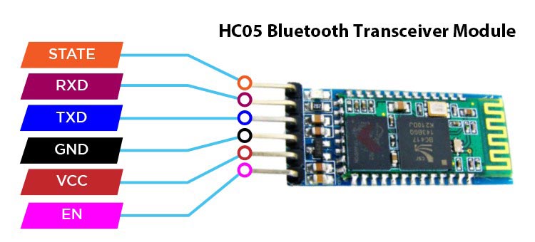
Now, we try to control an LED using Bluetooth module from the phone. For that, we need to understand the bluetooth module.
First we used the UART port to connect the Bluetooth module but it didn't work, receiver was displayed gibberish in the serial monitor.
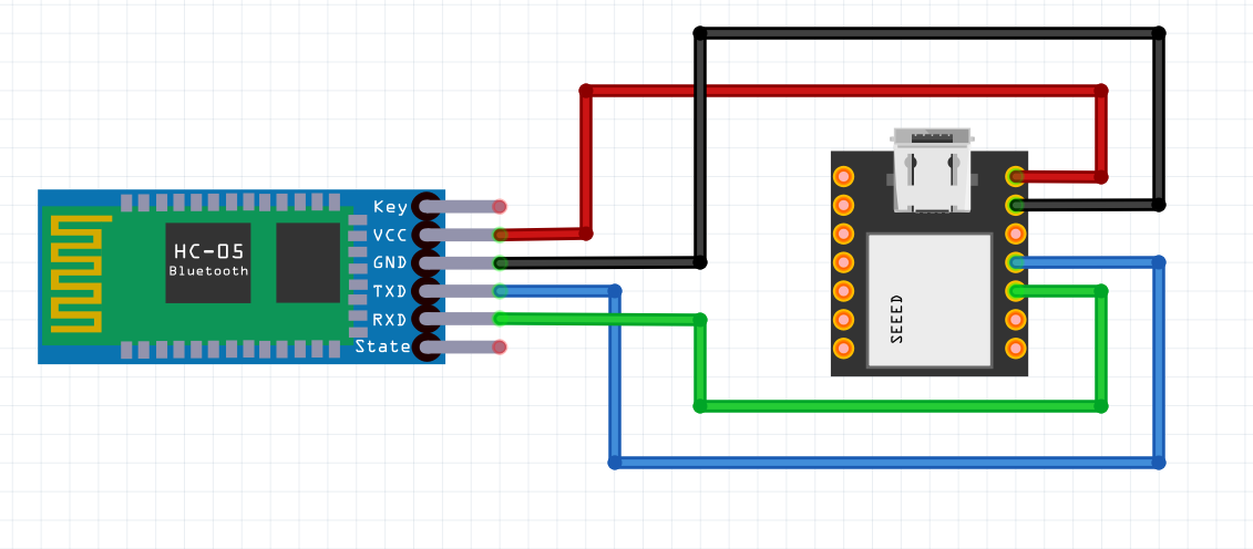
So we used the GPIO pins available and made the appropriate connections.
Connect RX of HC-05 to D7 of Quentorres board. In the same way connect TX to D6, GND to GND and VCC to VCC.
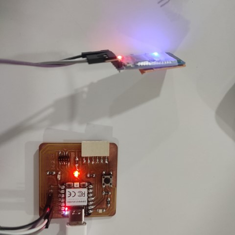
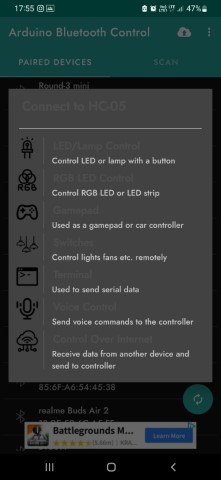
Connect via bluetooth to the module. The name is HC-05 and using the app Arduino Bluetooth control, we can have a lot of options.
I chose used to send serial data.
Here is a snippet of led on and off via the values 1 and 0 entered from phone in arduino bluetooth control app.
    #include < SoftwareSerial.h >

    const int ledPin = 0; // GPIO pin for the LED
    SoftwareSerial bluetoothSerial(3, 4); // RX, TX pins for HC-05

    void setup() {
        Serial.begin(9600);          // Initialize the serial communication for debugging
        bluetoothSerial.begin(9600); // Initialize Bluetooth serial communication
        pinMode(ledPin, OUTPUT);      // Set the LED pin as an output
    }

    void loop() {
        if (bluetoothSerial.available() > 0) {
        char command = bluetoothSerial.read();

        // Toggle LED based on received command
        if (command == '1') {
            digitalWrite(ledPin, HIGH); // Turn on LED
            Serial.println("LED ON");
        } else if (command == '0') {
            digitalWrite(ledPin, LOW);  // Turn off LED
            Serial.println("LED OFF");
        }
      }
    }
Extras
MicroPython
MicroPython is a specialized Python implementation for embedded systems, offering partial native code compilation for improved performance and reduced resource usage.
Unlike CPython, it's optimized for microcontrollers and constrained devices. While it supports a subset of Python 3.5 features, it excels in tasks requiring low-level hardware control and interfacing with sensors, making it ideal for IoT applications.
MicroPython's unique features cater to embedded development needs, but its limitations compared to CPython should be considered. Detailed comparisons between MicroPython and other implementations provide insights into their differences and suitability for various use cases.
I referred this documentation and followed the same steps.
You can see the LED light turn on and off once a second. And the output of the increasing number is displayed in the Shell.
    from machine import Pin, Timer
    led = Pin(25, Pin.OUT)
    Counter = 0
    Fun_Num = 0

    def fun(tim):
        global Counter
        Counter = Counter + 1
        print(Counter)
        led.value(Counter%2)

    tim = Timer(-1)
    tim.init(period=1000, mode=Timer.PERIODIC, callback=fun)
You can see the RGB LED light convert and flash the lights. And the output of the text "Beautiful Color" is displayed in the Shell.
    from ws2812 import WS2812
    import utime
    import machine
    power = machine.Pin(11,machine.Pin.OUT)
    power.value(1)
    BLACK = (0, 0, 0)
    RED = (255, 0, 0)
    YELLOW = (255, 150, 0)
    GREEN = (0, 255, 0)
    CYAN = (0, 255, 255)
    BLUE = (0, 0, 255)
    PURPLE = (180, 0, 255)
    WHITE = (255, 255, 255)
    COLORS = (BLACK, RED, YELLOW, GREEN, CYAN, BLUE, PURPLE, WHITE)

    led = WS2812(12,1)#WS2812(pin_num,led_count)

    while True:
        print("Beautiful color")
        for color in COLORS:
            led.pixels_fill(color)
            led.pixels_show()
            utime.sleep(0.2)
CircuitPython
CircuitPython is a programming language designed to simplify experimenting and learning to program on low-cost microcontroller boards.
It makes getting started easier than ever with no upfront desktop downloads needed.
Once you get your board set up, open any text editor, and get started editing code. It's that simple.
I referred this documentation and followed the same steps.
You can see the LED light turn on and off once a second.
    import time
    import board
    import digitalio

    led = digitalio.DigitalInOut(board.LED)
    led.direction = digitalio.Direction.OUTPUT

    while True:
        led.value = True
        time.sleep(0.5)
        led.value = False
        time.sleep(0.5)
PlatformIO
PlatformIO is an open-source ecosystem for IoT development, offering a unified environment for microcontroller projects.
Compatible with Windows, macOS, and Linux, it supports various platforms like Arduino, ESP8266, and STM32. Integrated with popular code editors, it simplifies code writing, compilation, and upload processes. With a built-in library manager, terminal, and project configuration file, it streamlines development tasks. Highly extensible, PlatformIO enables custom platform, board, and framework creation, catering to diverse project needs.
Ideal for hobbyists and professionals, PlatformIO provides a versatile solution for embedded systems development.
I created a new project and selected board as Raspberry Pi Pico since our board wasn't available on the list.
I wrote code for blinking LED and build the code sucessfully but I wasn't able to upload due to an error.
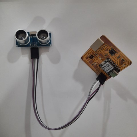
External Component
To integrate an ultrasonic sensor with a Seeed Xiao RP2040 we need to understand the pinout of the sensor.
1. Connect the trigger pin of the ultrasonic sensor to digital pin D9 on the Seeed Xiao RP2040.
2. Connect the echo pin of the ultrasonic sensor to digital pin D10 on the Seeed Xiao RP2040.
3. Connect the ground (GND) pin of the ultrasonic sensor to a ground pin (GND) on the Seeed Xiao RP2040.
4. Connect the VCC pin of the ultrasonic sensor to a 5V pin on the Seeed Xiao RP2040.
5. Next we need to write that code sets up the trigger pin (D9) as an output and the echo pin (D10) as an input. It sends a trigger pulse,
measures the time taken for the pulse to bounce back (which corresponds to the distance), and then calculates and prints the distance in centimeters and duration of pulse received.
    #define TRIG_PIN D9
    #define ECHO_PIN D10

    void setup() {
        Serial.begin(9600);
        pinMode(TRIG_PIN, OUTPUT);
        pinMode(ECHO_PIN, INPUT);
    }

    void loop() {
        long duration, distance_cm;

        // Clear the trigger pin
        digitalWrite(TRIG_PIN, LOW);
        delayMicroseconds(2);

        // Send a 10 microsecond pulse to trigger ranging
        digitalWrite(TRIG_PIN, HIGH);
        delayMicroseconds(10);
        digitalWrite(TRIG_PIN, LOW);

        // Measure the pulse duration on the echo pin
        duration = pulseIn(ECHO_PIN, HIGH);

        // Print debug information
        Serial.print("Duration: ");
        Serial.print(duration);
        Serial.println(" microseconds");

        // Calculate distance in centimeters
        distance_cm = duration * 0.034 / 2;

        // Print debug information
        Serial.print("Distance: ");
        Serial.print(distance_cm);
        Serial.println(" cm");

        // Check for valid readings (within range of the sensor)
        if (distance_cm >= 2 && distance_cm <= 400) {
        Serial.print("Valid Distance: ");
        Serial.print(distance_cm);
        Serial.println(" cm");
        } else {
        Serial.println("Out of range");
        }

        delay(1000); // Delay for readability
    }
Next, I tried to write a program using the NewPing library for Arduino, which simplifies the task of interfacing with ultrasonic sensors. You'll need to install the NewPing library through the Arduino Library Manager if you haven't already.
    #include < NewPing.h >

    #define TRIGGER_PIN 9
    #define ECHO_PIN 10
    #define MAX_DISTANCE 200 // Maximum distance we want to ping for (in centimeters). Maximum sensor distance is rated at 400-500cm.

    NewPing sonar(TRIGGER_PIN, ECHO_PIN, MAX_DISTANCE); // NewPing setup of pins and maximum distance.

    void setup() {
        Serial.begin(9600); // Open serial monitor at 9600 baud to see distance readings.
    }

    void loop() {
        delay(50);                      // Wait 50ms between pings (about 20 pings/sec). 29ms should be the shortest delay between pings.
        unsigned int distance_cm = sonar.ping_cm(); // Send ping, get distance in centimeters and print result (0 = outside set distance range)

        if (distance_cm == 0) {
        Serial.println("Out of range");
        } else {
        Serial.print("Distance: ");
        Serial.print(distance_cm);
        Serial.println(" cm");
        }
    }
.png)
.png)
.png)
.png)
.png)
.jpg)
.png)
.png)
.png)
.png)
.png)