Networking & Communications
Objectives for Week 13
- Design, build, and connect wired or wireless node(s) with network or bus addresses and local input &/or output device(s)
- Group Assignment:
- Send a message between two projects
This week was to create communication between boards either wired or wireless.
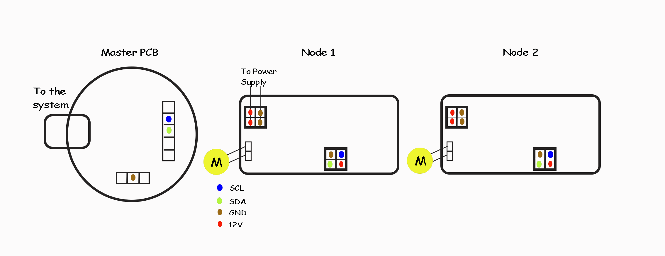
I chose I2C connection and planned on using DC Motors as the output device so that I could check if it can be used for my final project. I plan to use a board that I have created previously as the master and two Node boards that I'll be designing this week which will house the motor drivers as well.
I2C Serial Communication
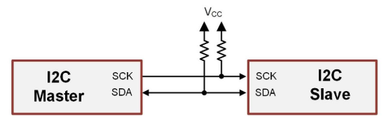
The Inter-Integrated Circuit (I2C) standard is a serial interface implementation with a two-wire link that can support multiple masters and multiple Nodes. An I2C bus contains a clock line (SCL) and data line (SDA).
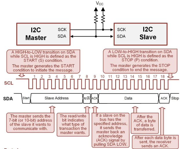
I2C Protocol
An I2C bus ALWAYS needs external pull-up resistors on each of its lines. These can’t be implemented on the MCU because the resistor function is only available when the port is configured as an INPUT. Since I2C is bidirectional, we never know wither the pin will be an input or output.
Master: device that initiates communication and controls the clock.
Node: device on the bus that is read or written to, but does not initiate transmission or provide a clock.
A master initiates a new message by generating a START (S) condition by pulling SDA LOW while SCL is still HIGH. As soon as the START condition is generated, the SCL will be pulled LOW and start pulsing to provide the clock message.
Master PCB
I'm using the board that I designed during Electronics Design week as the master.
I have taken out the I2C pins out along with other required pins.
Refer documentation of Week 8 to know about the board.
Node PCB
The board I'll be creating this week houses ATtiny412 as the microcontroller with A4953 as the motor driver for DC Motor.
ATtiny412
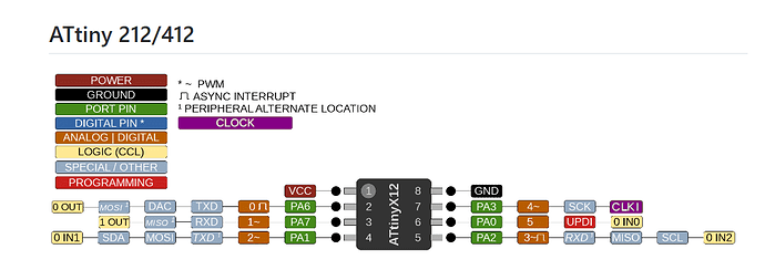
The ATtiny412 is based on the AVR processor architecture, and it is specifically designed for applications where space and power efficiency are critical.
Features:
- 8-bit AVR microcontroller
- Flash memory: 4 KB
- Wide operating voltage range (1.8V to 5.5V)
- UPDI (Unified Program and Debug Interface) for programming and debugging
DC Motor
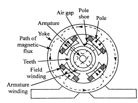
The DC motor is the motor which converts the direct current into the mechanical work. It works on the principle of Lorentz Law, which states that “the current carrying conductor placed in a magnetic and electric field experience a force”. And that force is the Lorentz force.
There are two main parts of the DC motor.
- Armature
- Stator
The rotating part is the armature and the Stator is their stationary part. The armature coil is connected to the DC supply.
A4953 Motor Driver
For my current final project idea, I plan to use DC motor for flipping the tiles, hence, I plan to use DC as this weeks output week. To use this motor, we require a driver motor and I'm using A4953.
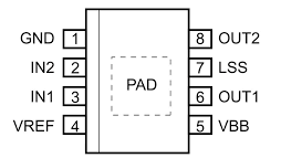
Pin Configuration and Description
- VBB - Load supply voltage
- GND - Ground
- IN1 and IN2 - Logic inputs
- OUT1 and OUT2 - DMOS full bridge output
- LSS - Power return (sense resistor connection)
- PAD - Exposed pad for enhanced thermal dissipation
- VREF - Analog input
Features:
- Output Current: The A4953 is capable of driving up to 3.5 A peak output current per phase.
- Supply Voltage: Operates across a broad range of supply voltages, typically from 8 V to 40 V, making it versatile for various application needs.
- PWM Control: Supports PWM control inputs, which are commonly used for adjusting motor speed and torque in various applications.
- Full-Bridge Output: Capable of driving a single bipolar stepper motor or two DC motors with forward and reverse control.
PCB Design
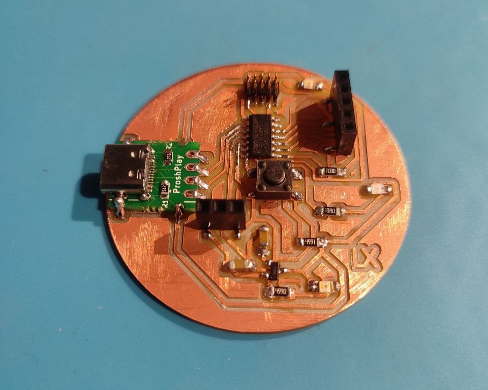
The Node boards I'm creating this week consists of the microcontroller, motor driver, I2C Serial communication pins, voltage regulator, one LED and other basic requirements. Here's the schematic diagram showcasing all the components.
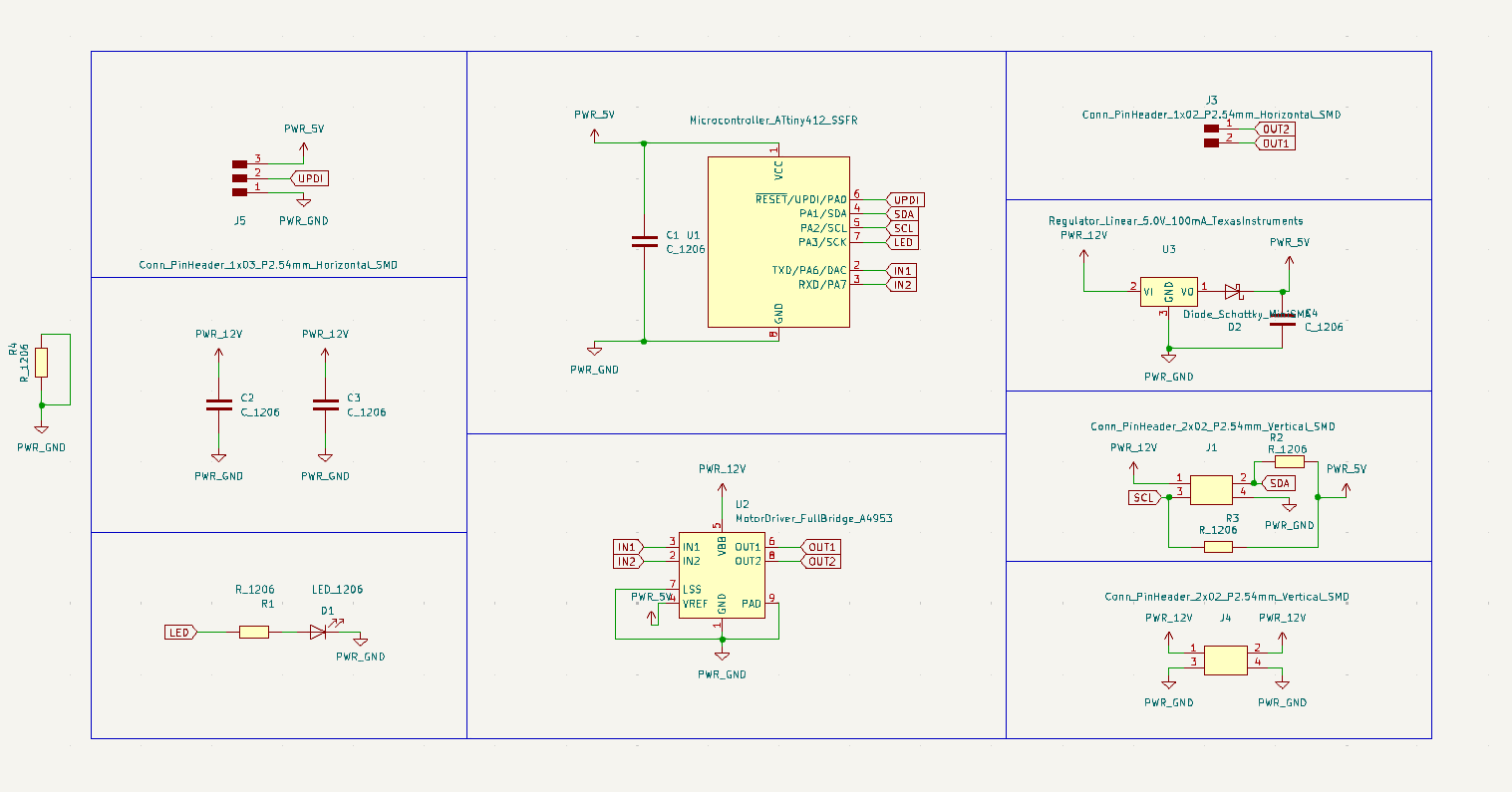
This is the final schematic diagram. In between there has been several editions. Things like adding the Schottky diode for Voltage Regulator, pull-up resistors for I2C were actually forgotten and had to be added in between and routed. Once, all the necessary components were added, I moved to tracing.
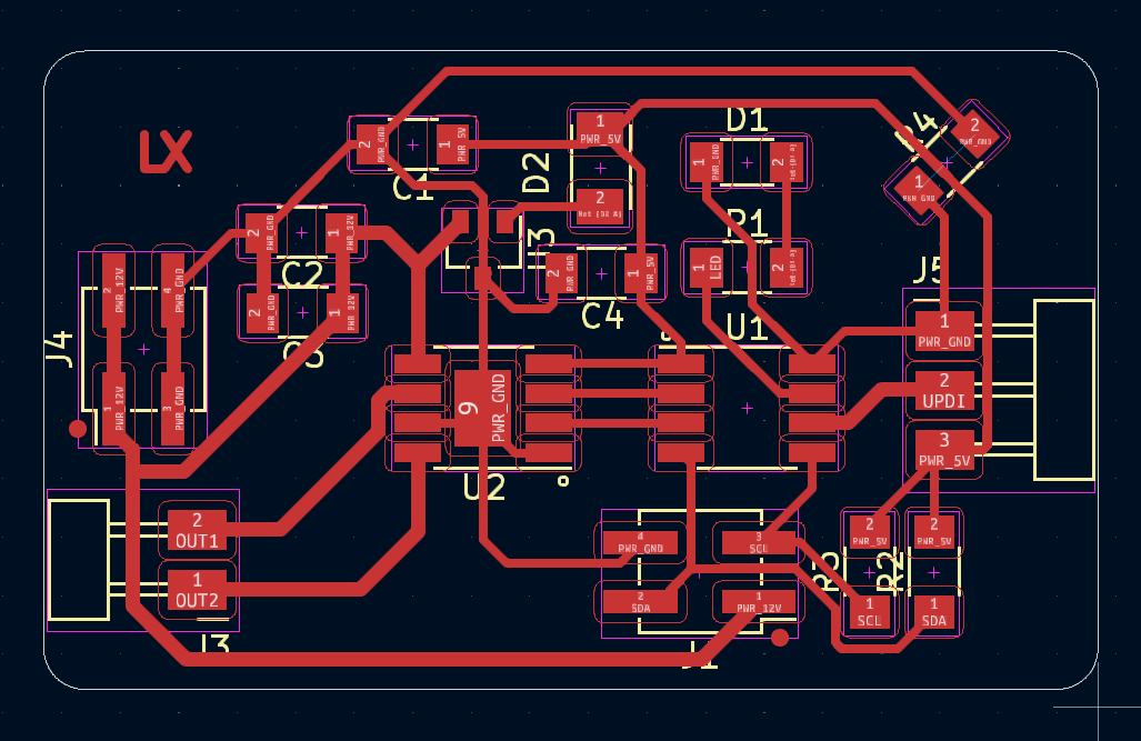
First, I set all the required constraints and then arranged the components so that the routing would be less complicated.
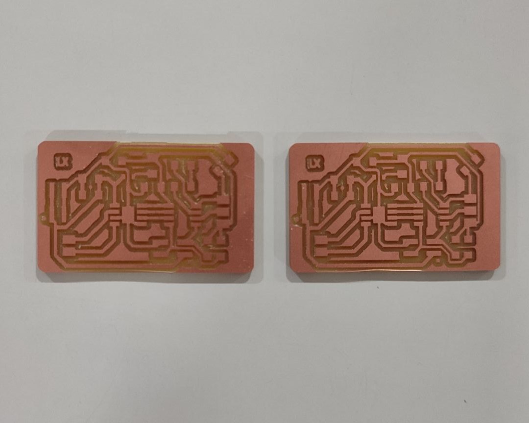
Here's the final PCB layout.
PCB Milling
The next step is milling the PCB. I am using Roland Modela MDX20 along with MODs for the purpose. I have been using the same machine so far for milling all the boards I have created. So, milling process went quite easy.
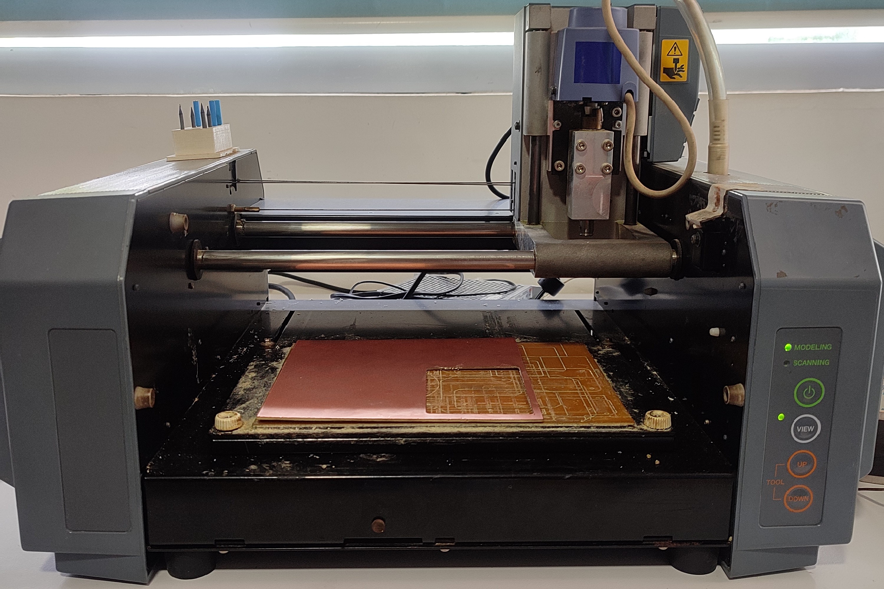
Refer documentation of Week 4 to know about the working processes of Roland Modela MDX20 and MODs.
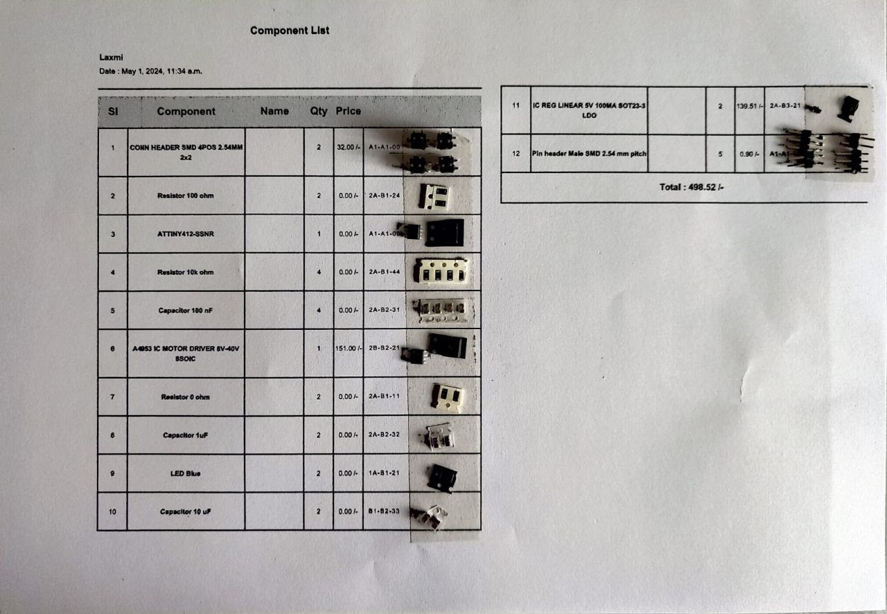
The next step is to request for the required components from Fab Inventory. The component list is as below:
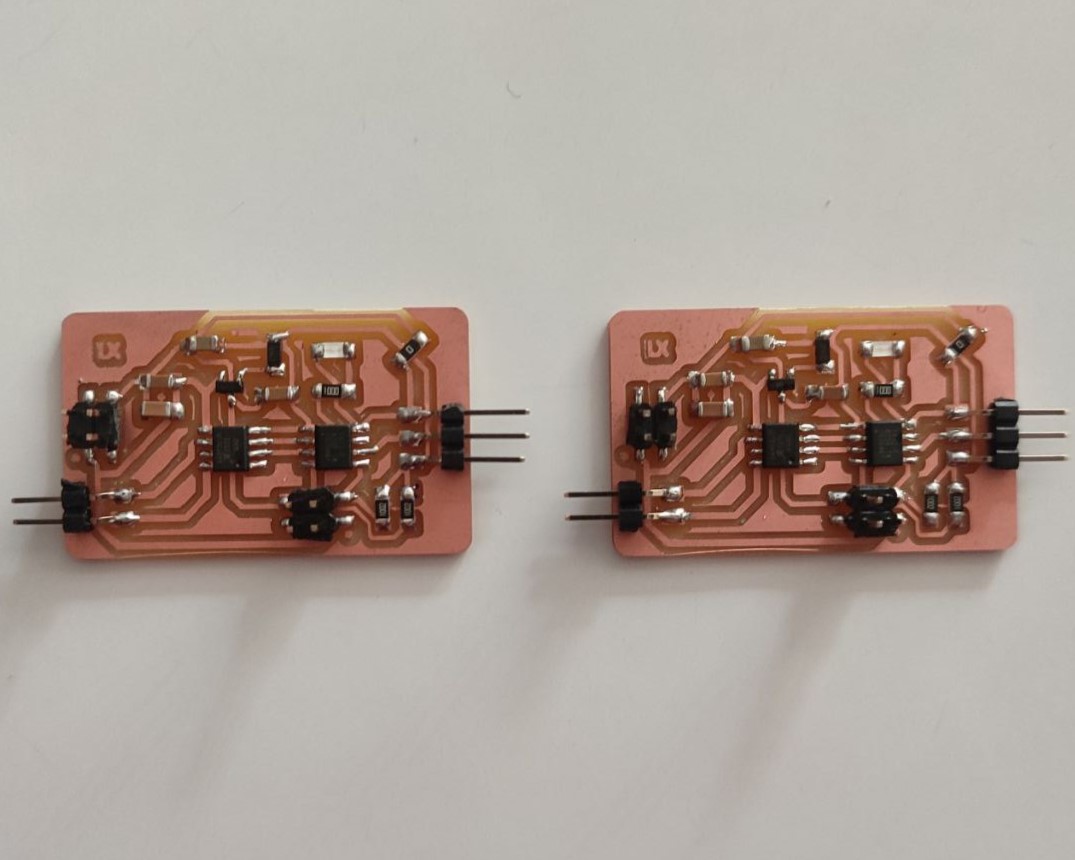
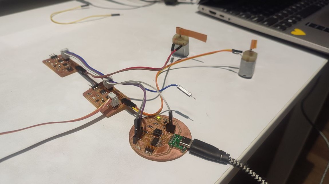
Then I started soldering the components to the two boards and this is how it finally turned out.
Programming
After creating the board, I tried uploading the 'Blink' code from example with Quentorres as the programmer to light up the LEDs I have provided to see if the board is working. Both the boards were working fine.
Since both my Nodes has LED, next, I tried communicating using these LED. I used ChatGPT to generate the codes for my master and Nodes. I gave ChatGPT the following prompt:
Write an arduino code for master and two Nodes where master has SAMD11C14A as microcontroller and has a button; I have two same Node PCBs with ATtiny412 microcontroller with 1 LED each and they are working in I2C Serial Communication; when the button on master is pressed first, it will print 1 and the LED in the first Node PCB will light up; when the button is pressed again, it will print 2 and the LED in second Node PCB lights up; on pressing the button the third time, it prints 3 and both LEDs goes off, and this goes on loop.
And just as it, ChatGPT gave the codes. I modified the code according to my requirement and here's the modified code.
Code for Master PCB
    #include < Wire.h>

      #define BUTTON_PIN 4   // Referred from my schematic diagram
      #define Node_ADDRESS1 0x08 //I2C Address for Node 1
      #define Node_ADDRESS2 0x09 //I2C Address for Node 2

      int currentState = 0;
      bool lastButtonState = HIGH; // Assuming button is pulled-up

      void setup() {
        pinMode(BUTTON_PIN, INPUT_PULLUP);
        Wire.begin(); // Start I2C as master
        Serial.begin(9600);
      }

      void loop() {
        bool currentButtonState = digitalRead(BUTTON_PIN);

        // Check for button press
        if (currentButtonState == LOW && lastButtonState == HIGH) {
          delay(50); // Debounce delay
          currentState = (currentState + 1) % 3; // Cycle through states 0, 1, 2
          handleStateChange(currentState);
          Serial.println(currentState + 1);
          while(digitalRead(BUTTON_PIN) == LOW); // Wait until button is released
        }

        lastButtonState = currentButtonState;
      }

      void handleStateChange(int state) {
        switch(state) {
          case 0:
            sendCommand(Node_ADDRESS1, 1); // LED on
            sendCommand(Node_ADDRESS2, 0); // LED off
            break;
          case 1:
            sendCommand(Node_ADDRESS1, 0); // LED off
            sendCommand(Node_ADDRESS2, 1); // LED on
            break;
          case 2:
            sendCommand(Node_ADDRESS1, 0); // LED off
            sendCommand(Node_ADDRESS2, 0); // LED off
            break;
        }
      }

      void sendCommand(int address, int command) {
        Wire.beginTransmission(address);
        Wire.write(command);
        Wire.endTransmission();
      }
Code for Node 1 PCB
    #include < Wire.h>

      #define LED_PIN 4 // Referred from my schematic diagram
      #define I2C_ADDRESS 0x08 //I2C Address of Node 1

      void setup() {
        pinMode(LED_PIN, OUTPUT);
        Wire.begin(I2C_ADDRESS); // Set this device's address
        Wire.onReceive(receiveEvent); // Register event for receiving data
      }

      void loop() {
      }

      void receiveEvent(int howMany) {
        if (Wire.available()) {
          int received = Wire.read(); // Read the command sent by the master
          if (received == 1) {
            digitalWrite(LED_PIN, HIGH); // Turn LED on
          } else {
            digitalWrite(LED_PIN, LOW); // Turn LED off
          }
        }
      }
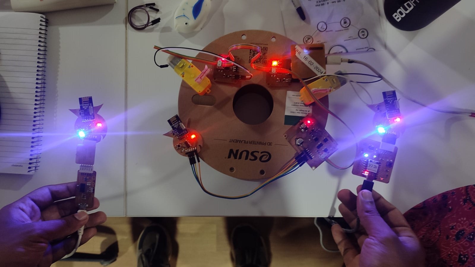
Same goes for Node 2. Only the I2C address changes. You can download the code from below. Here's the result.
Code for DC Motors
As I have done for the LED communication, with the help of ChatGPT, I generated codes for running DC motors with the Nodes. The working of the codes is as following: When the button on the Master PCB is pressed, the DC motor on Node 1 starts running; when the button is pressed again, the DC Motor on Node 1 stops and DC Motor on Node 2 starts running; on pressing the button the third time, DC Motor on Node 2 stops. Here's the codes for the following process.
Code for Master PCB
    #include < Wire.h>

      const int buttonPin = 4;   // The pin where the button is connected
      int lastButtonState = LOW; // The previous reading from the input pin
      int currentState = 0;      // State of the application

      void setup() {
        pinMode(buttonPin, INPUT);
        Wire.begin(); // Start I2C as master
        Serial.begin(9600);
      }

      void loop() {
        int buttonState = digitalRead(buttonPin);

        // Check if the button has been pressed
        if (buttonState == HIGH && lastButtonState == LOW) {
          delay(50); // Debouncing
          currentState++;
          if (currentState > 2) currentState = 0;

          switch (currentState) {
            case 0:
              sendCommand(0x08, 0); // Stop motor on Node 1
              sendCommand(0x09, 0); // Stop motor on Node 2
              break;
            case 1:
              sendCommand(0x08, 1); // Start motor on Node 1
              sendCommand(0x09, 0); // Ensure motor on Node 2 is stopped
              break;
            case 2:
              sendCommand(0x08, 0); // Stop motor on Node 1
              sendCommand(0x09, 1); // Start motor on Node 2
              break;
          }
        }

        lastButtonState = buttonState; // Save the current state as the last state, for next time through the loop
        delay(10);
      }

      void sendCommand(byte address, byte command) {
        Wire.beginTransmission(address);
        Wire.write(command);
        Wire.endTransmission();
      }
Code for Node 1 PCB
    #include < Wire.h>
      #include < avr/io.h>

      const int motorPin1 = 0; // Example motor control pin 1 (OUT1)
      const int motorPin2 = 1; // Example motor control pin 2 (OUT2)

      void setup() {
        pinMode(motorPin1, OUTPUT);
        pinMode(motorPin2, OUTPUT);
        Wire.begin(0x08); // Set this ATTiny as I2C Node with address 0x08
        Wire.onReceive(receiveEvent);
      }

      void receiveEvent(int howMany) {
        while (Wire.available()) {
          int command = Wire.read();
          if (command == 1) {
            // Turn motor in one direction
            digitalWrite(motorPin1, HIGH);
            digitalWrite(motorPin2, LOW);
          } else {
            // Stop motor
            digitalWrite(motorPin1, LOW);
            digitalWrite(motorPin2, LOW);
          }
        }
      }

      void loop() {

      }
Same goes for Node 2. Only the I2C address changes. You can download the code from below. Here's the result.
External power has to be supplied for the motor to run. Therefore, a DC Power Supply was used.
- Voltage: 8V
- Current: 0.1A
Group Assignment
This week's group assingment was to send a message between two projects. We chose Ansu's project, which is a wireless communication between NRF modules and Nihal's project, which works on I2C protocol.
For further details, click on the link below.
Group Assignment-Week 13Download Files
Node Schematic DiagramNode PCB Layout
Codes
• LED Communication (zip)
• DC Motor Communication (zip)