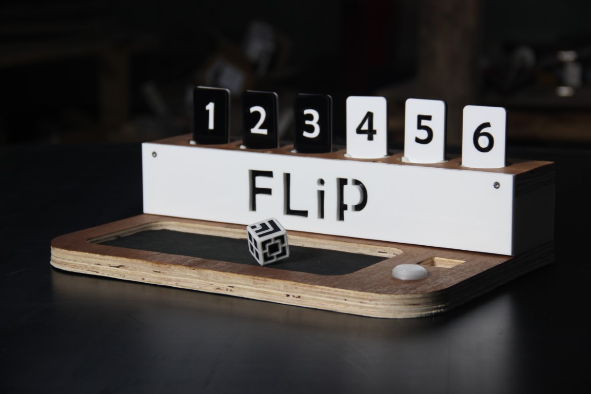
FLiP
I was planning to make an automated version of Snake & Ladder. Sometimes after Machine week, I came to the realization that the project could become hectic. Mainly because I find programming really difficult and it contains a lot of coding according to each sequences. So, I thought of changing my final project. I wanted to incorporate the die anyway because I found it really interesting and wants to give it a try. I started looking for games that can be played with dice and I came across 'Shut The Box'.
Shut The Box is a traditional dice game. It is typically played with one or more players.
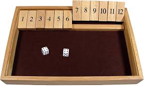
For my final project, I have modified the rules for the game. I named the game FLiP.
Who's done what beforehand?
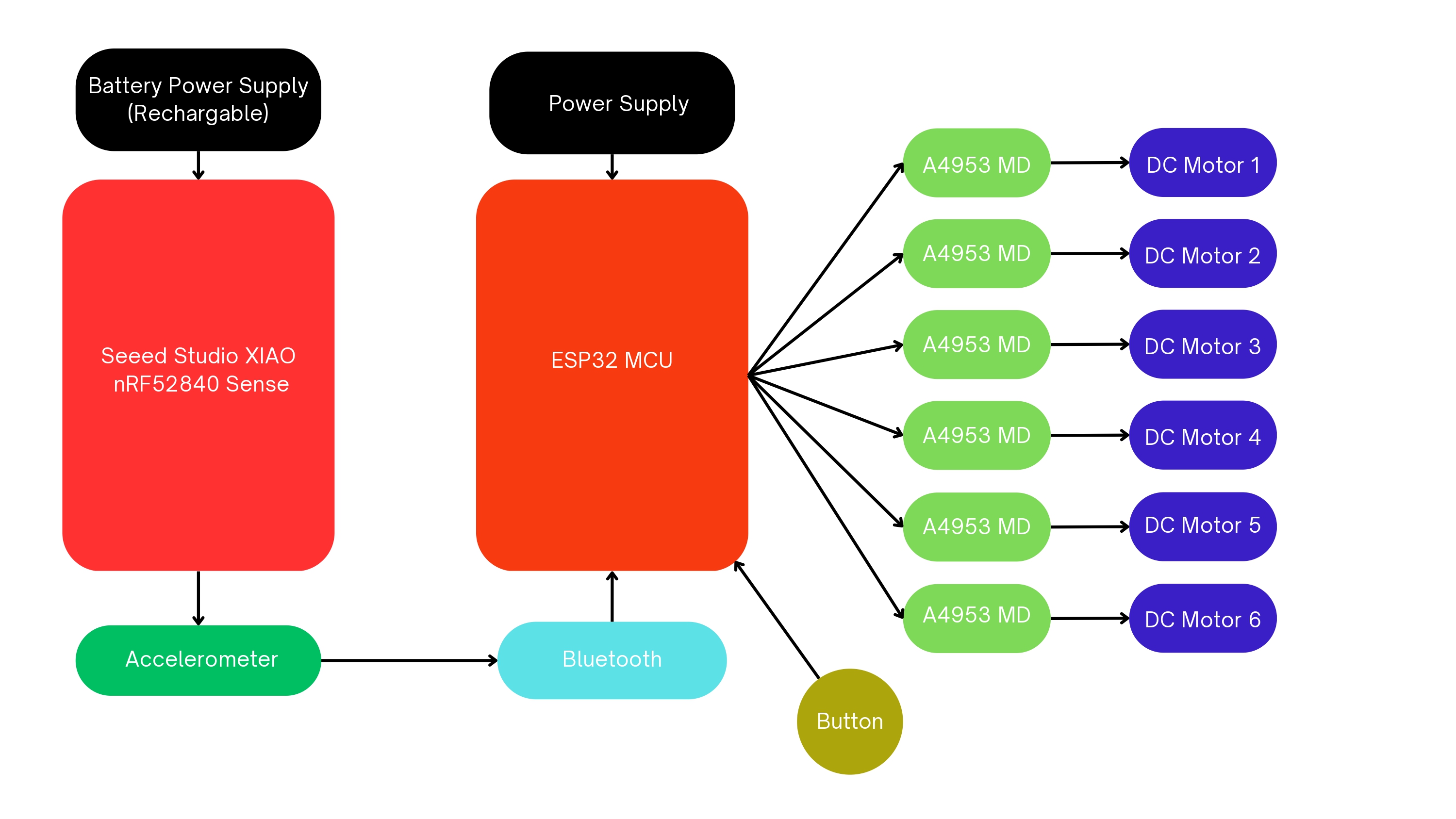
Smart Dice is a final project by Jonathan Bobrow from How to Make (Almost) Anything. He has made a dice that reports its orientation and value when rolled. I took the same concept but changed the components I'll be using to make the process easier. I'm using XIAO nRF52840 Sense for the orientation detection where I can also utilize its bluetooth connectivity as well as the Type-C out to charge the battery.
Shut the Box Web App Game
This is an online Shut the Box game developed by Mark Ledbetter using HTML, CSS, JavaScript and jQuery. My work will be a physical game set.
How to play FLiP?
The game is played between two players. The board will be having 6 two-sided tiles with numbering from 1 to 6. Let’s say the two sides of the tiles are black and white in colour. In the beginning of the game, tiles numbered from 1 to 3 will be showing its black colour and 4 to 6, white.
Players each choose a colour. Let's say player 1 chose black. So, their aim is to make all the tiles black by throwing the dice and flipping the corresponding number. Likewise, for player 2 with white.
As for flipping, from 3 to 6 there are different additional combination. See below for the different combinations available for each number. The combinations are in such a way that the sum of the number corresponds to the sum of the rolled number.
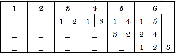
By pressing on the button, it shows the available combinations. If no combination along with the corresponding number is available, then that chance is skipped. On pressing the button each time, each combination will be shown by flipping the corresponding tile and for finalizing the position all you have to do is to lift the dice.
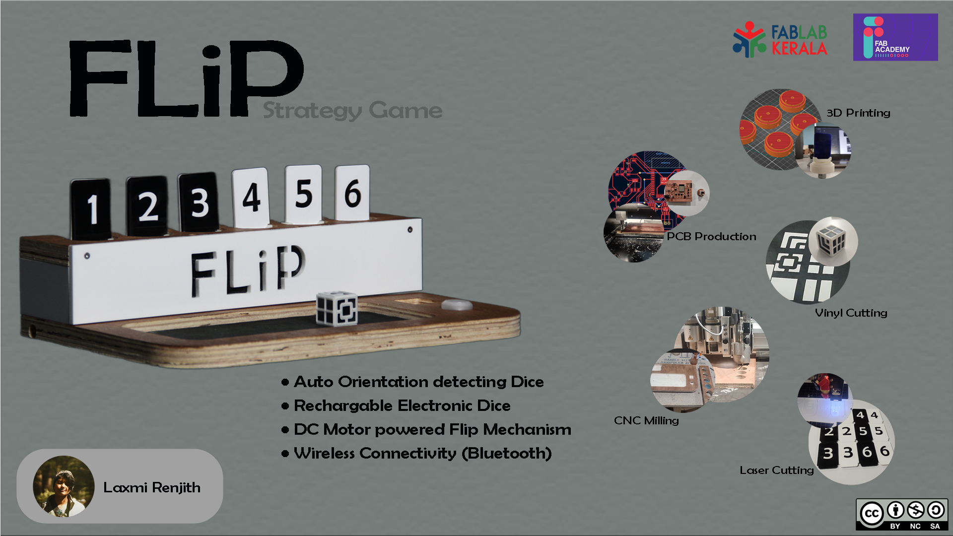
Features of FLiP
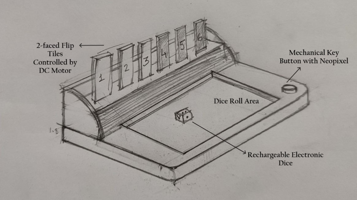
- A Type-C rechargable Dice that auto detects its orientation.
- 6 two-faced Flip Tiles controlled by DC Motors.
- Communication between Dice and Main Board via Bluetooth.
- Button (Mechanical Keyboard Switch) to view the available combinations.
- Neopixel to show the status of bluetooth connectivity at the begin of the game as well as to showcase each players' chance.
What processes were used?
- Laser Cutting: Cutting all the 6 tiles (Black and White 3mm thickness acrylic sheets), front panel (White 6mm thickness acrylic sheet), side panels (White 6mm thickness acrylic sheet) and back panel (Black 6mm thickness acrylic sheet) using Trotec Speedy 400 flexx.
- Wood CNC Milling: Milling plywood for the enclosure using Zund.
- PCB Milling and Soldering: Generate the PCBs required for the project using Roland Modela MDX20
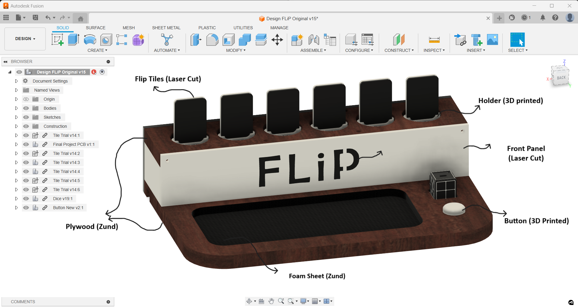
- Designing: 3D designing of the final project using Autodesk Fusion.
- 3D Printing: 3D printing the holders, base using Prusa i3 MK3 and dice using Bambu Labs.
- Vinyl Cutting: Vinyl cutting black stickers for Dice using Roland GX-24 Camm-1 Servo.
Dice
I wanted to make a dice that can auto detect its orientation. During Week 11, I tested out two different modules for detecting the orientation: MPU6050 and Seeed Studio XIAO nRF52840 Sense. I chose nRf52840 for my dice. Refer Input Devices to know how I used XIAO nRF52840 to get the orientations right.
Flip Mechanism
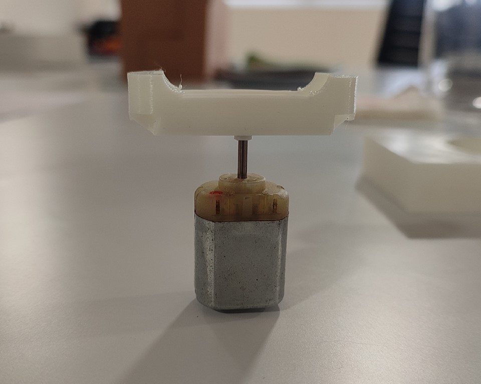
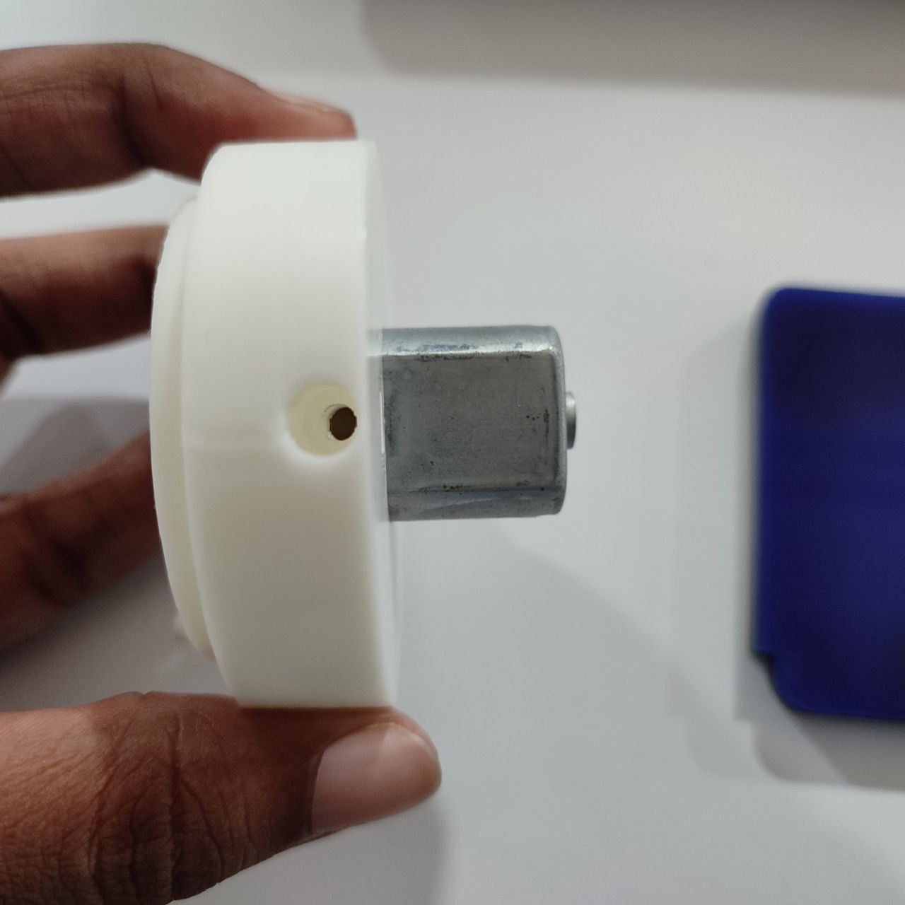
For my project, I have 6 tiles that have to flip 180° in vertical axis both the directions. First thought was to use servo motors because it requires only 1 pin per motor and the angle of rotation can be controlled. But the main problem that made me choose is the speed with which it rotates. Servo is much slower than DC Motor, thereby, it loses the lively effect of turning the tiles.
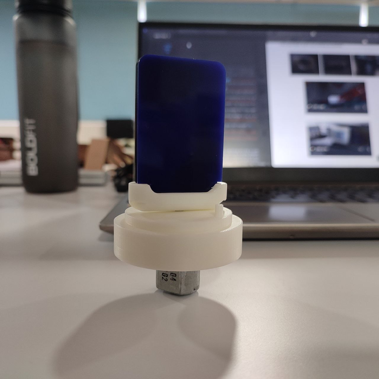
I 3D printed the parts to test the flip mechanism. I connected the motor to the system and tested it using the interface I had created during Week 14, where I was able to run the motor in both the direction to see if it stops at 180 (at the notch provided). And it was working successfully!
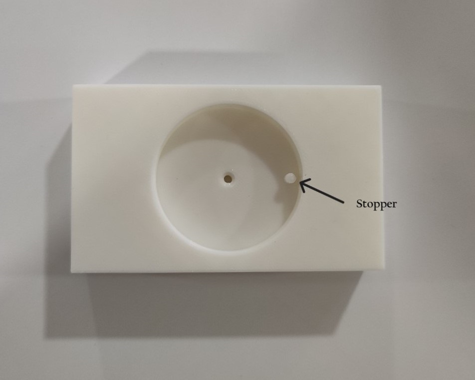
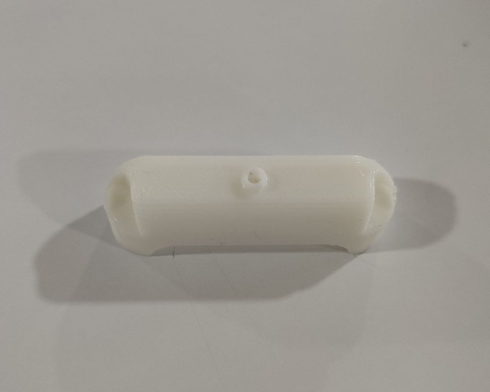
I later designed a separate base for the each module that can be glued to the plywood and also provision to hold the motor with the help of M3 is also provided. The sample acrylic tile was laser cut.
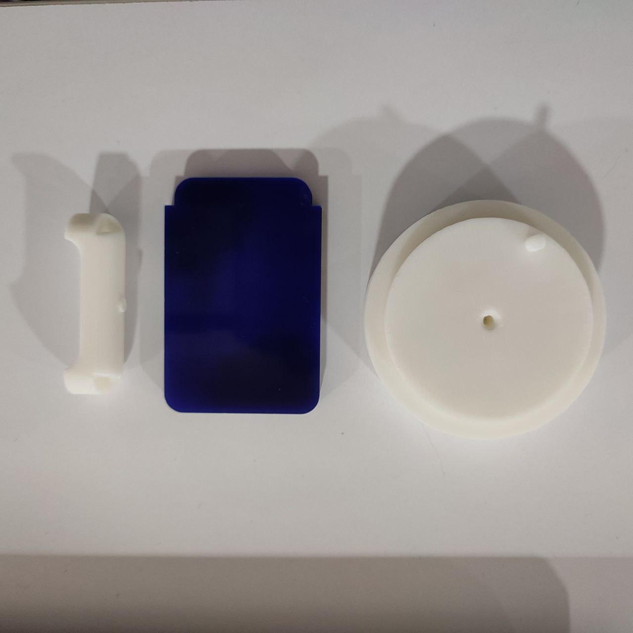
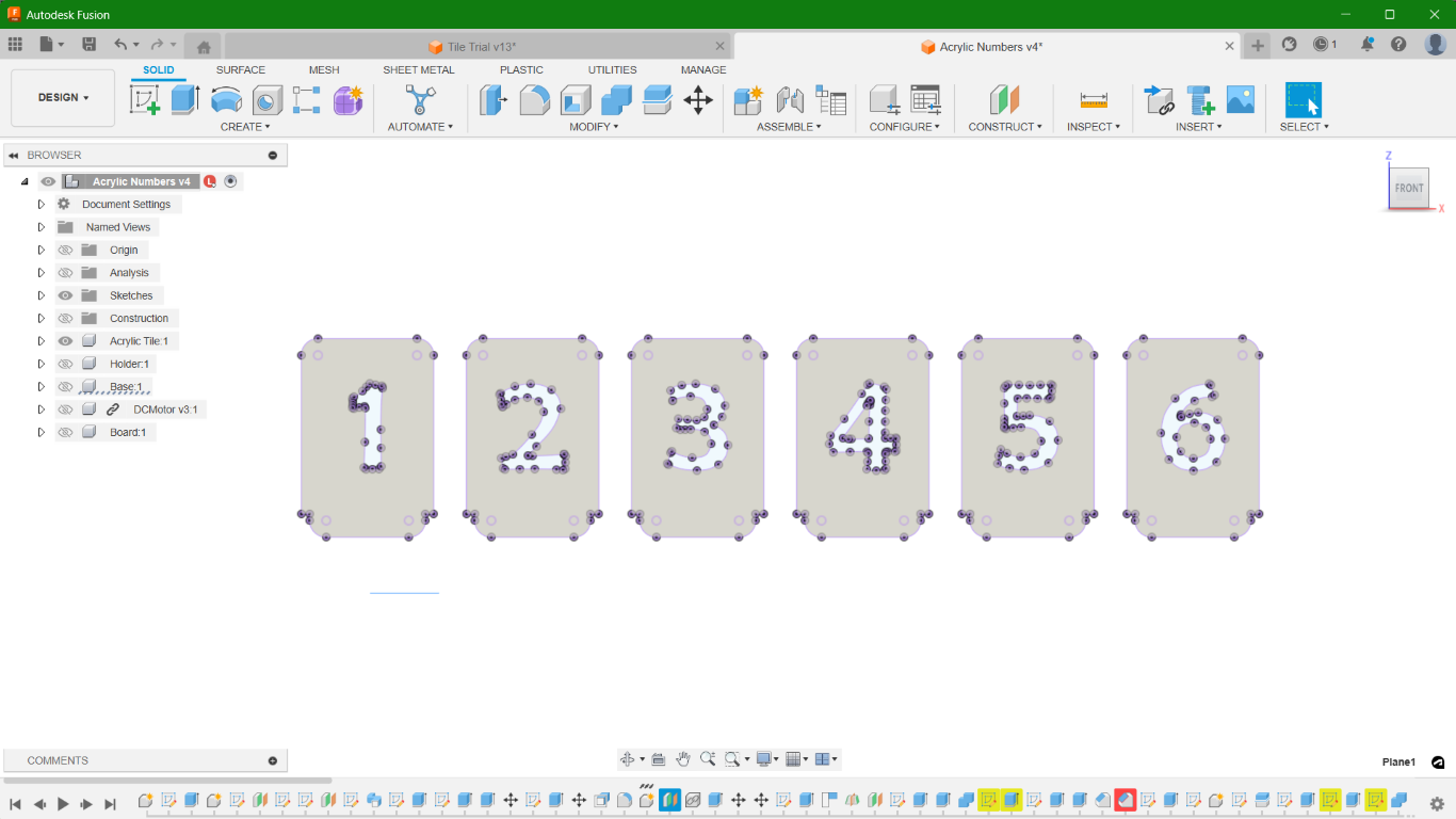
I 3D printed 6 of each and for the tiles. I created DXF of the numbers along with the tile and laser cut the pieces in both black and white acrylic sheet of 3mm thickness.
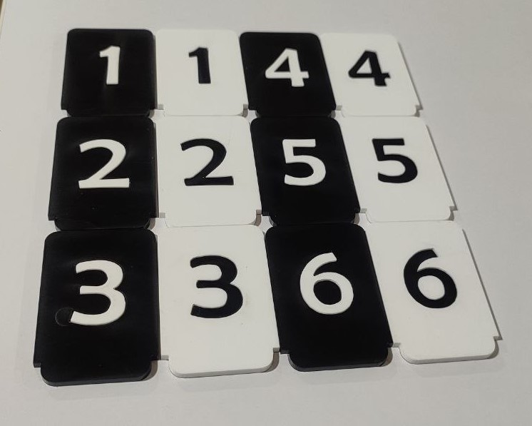
I glued them back to back and swapped the numbers across.
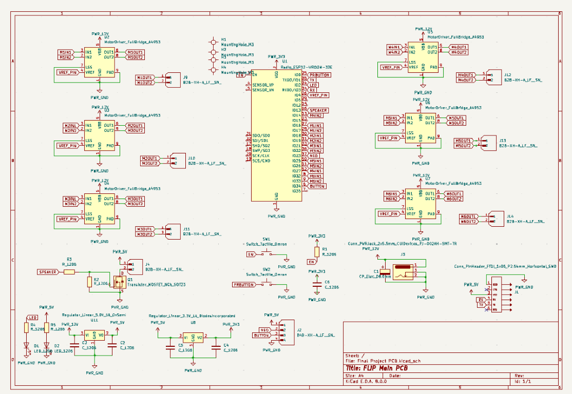
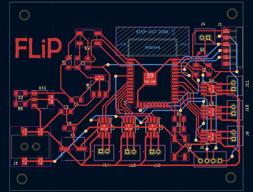
PCB Design
For FLiP, I have 3 PCB boards. One for the dice, the other one for a button and a neopixel and one main board. I designed all the three boards in KiCAD. All the design files including its gerber files are available to download from the bottom of this page.
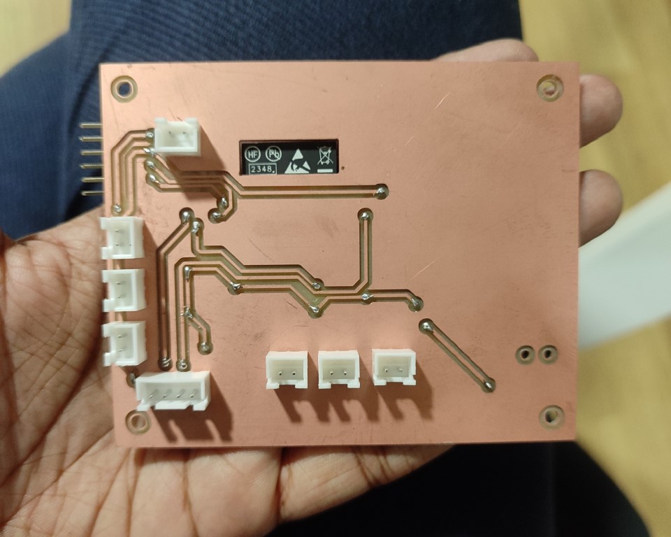
• Main Board
The main board controls all the 6 DC motors along with the A4953 motor driver and ESP32 WROOM 32E Microcontroller. The board also houses pin out for the other PCB (Neopixel and Button) and a power jack to connect the external 12V power supply.
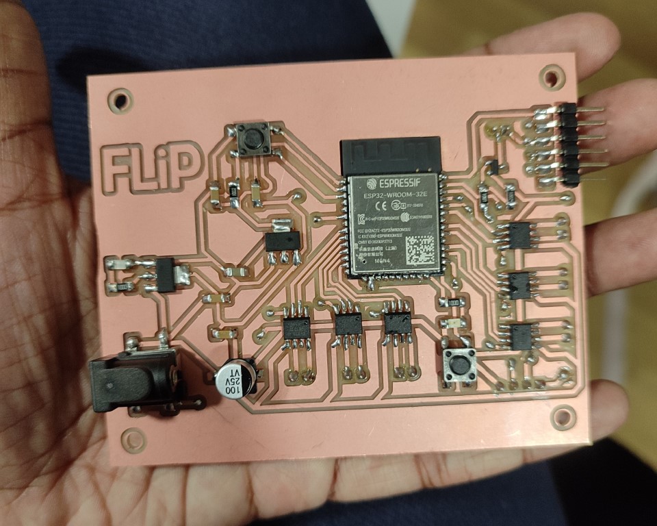
I checked if the board is working by uploading a simple blink code from the example. The board was working fine!
• PCB for Button & NeoPixel
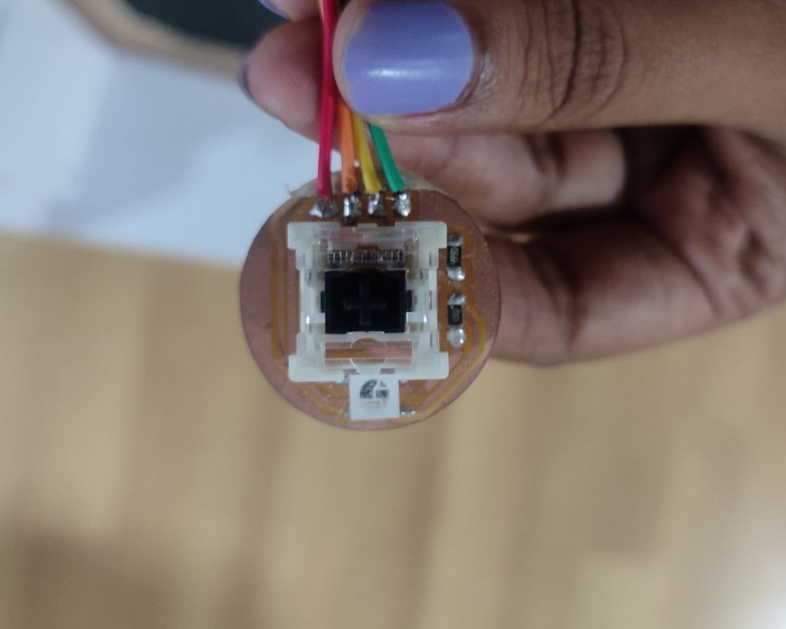
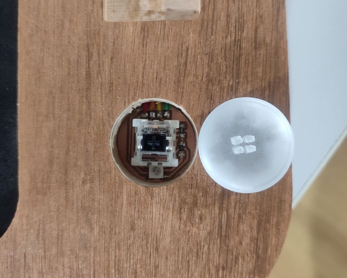
This PCB only includes mainly just the button, a neopixel and pads to connect to the main board. This board had to be separately made because it should be accessed from the outside. For the button I used a mechanical keyboard key switch.
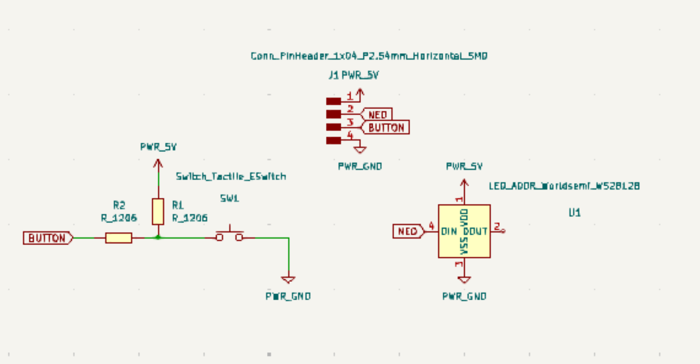
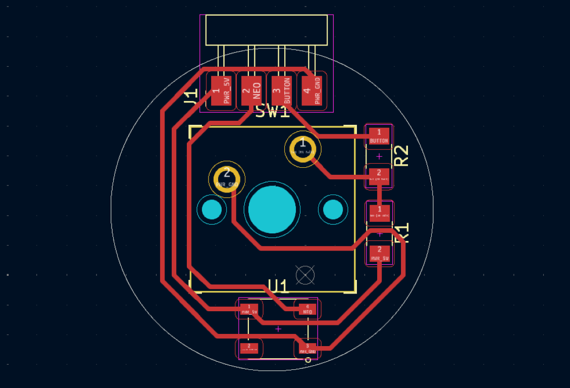
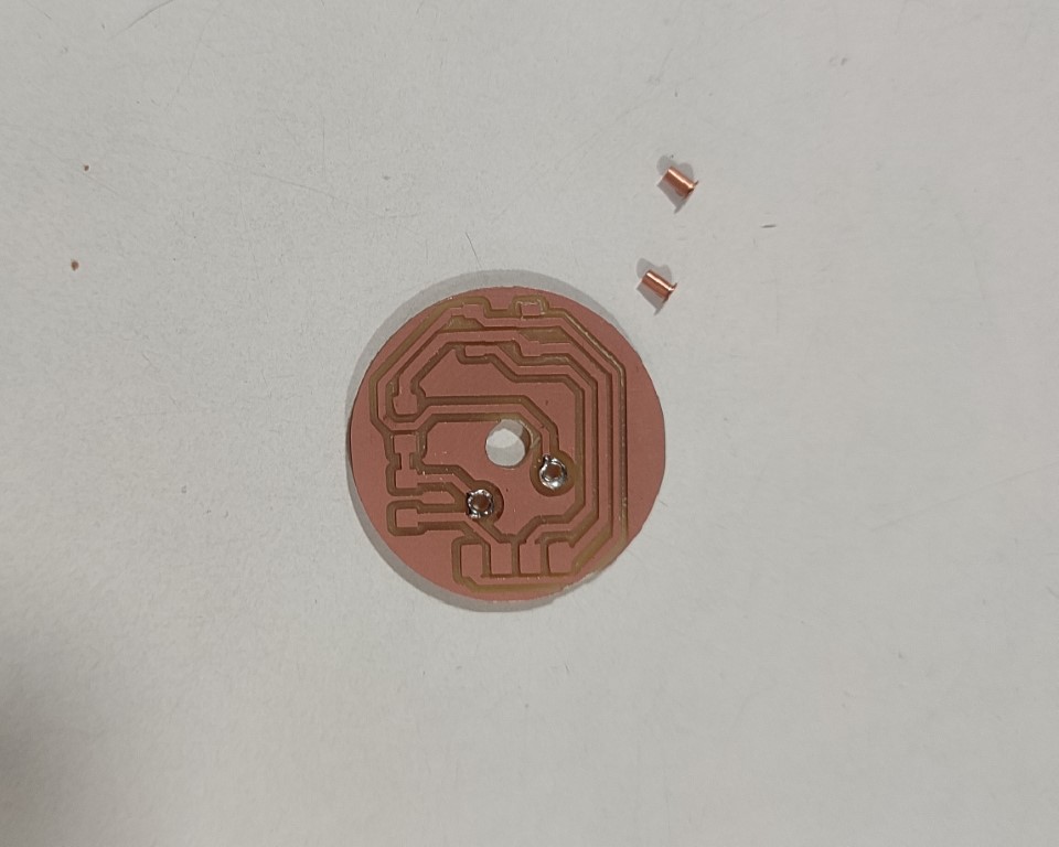
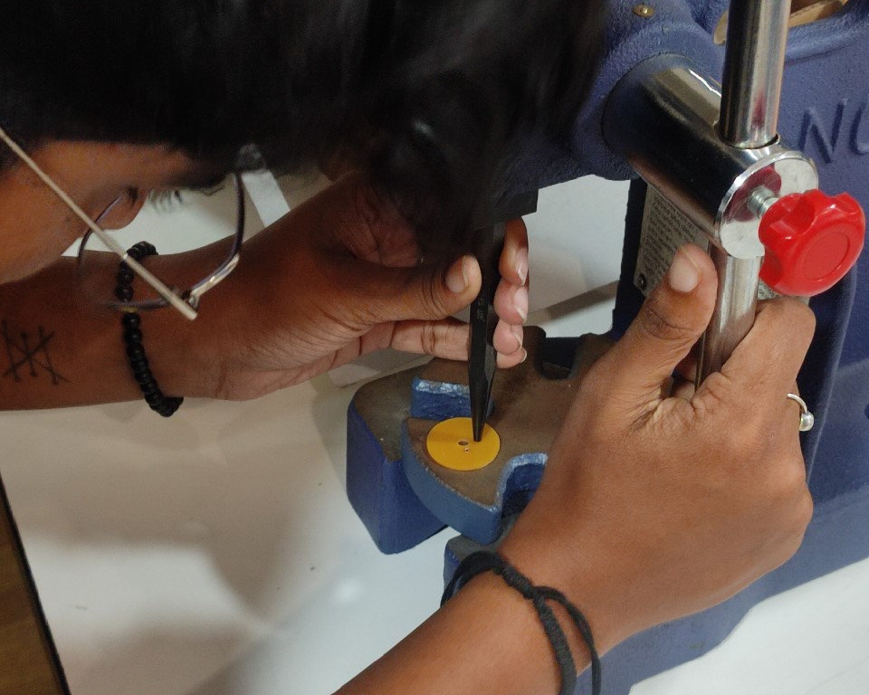
The PCB for the mechanical key switch was made single side and copper rivets were added for the switch.
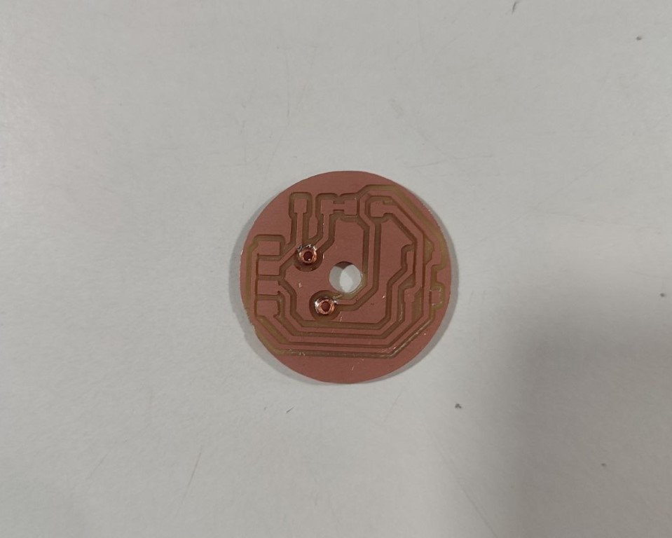
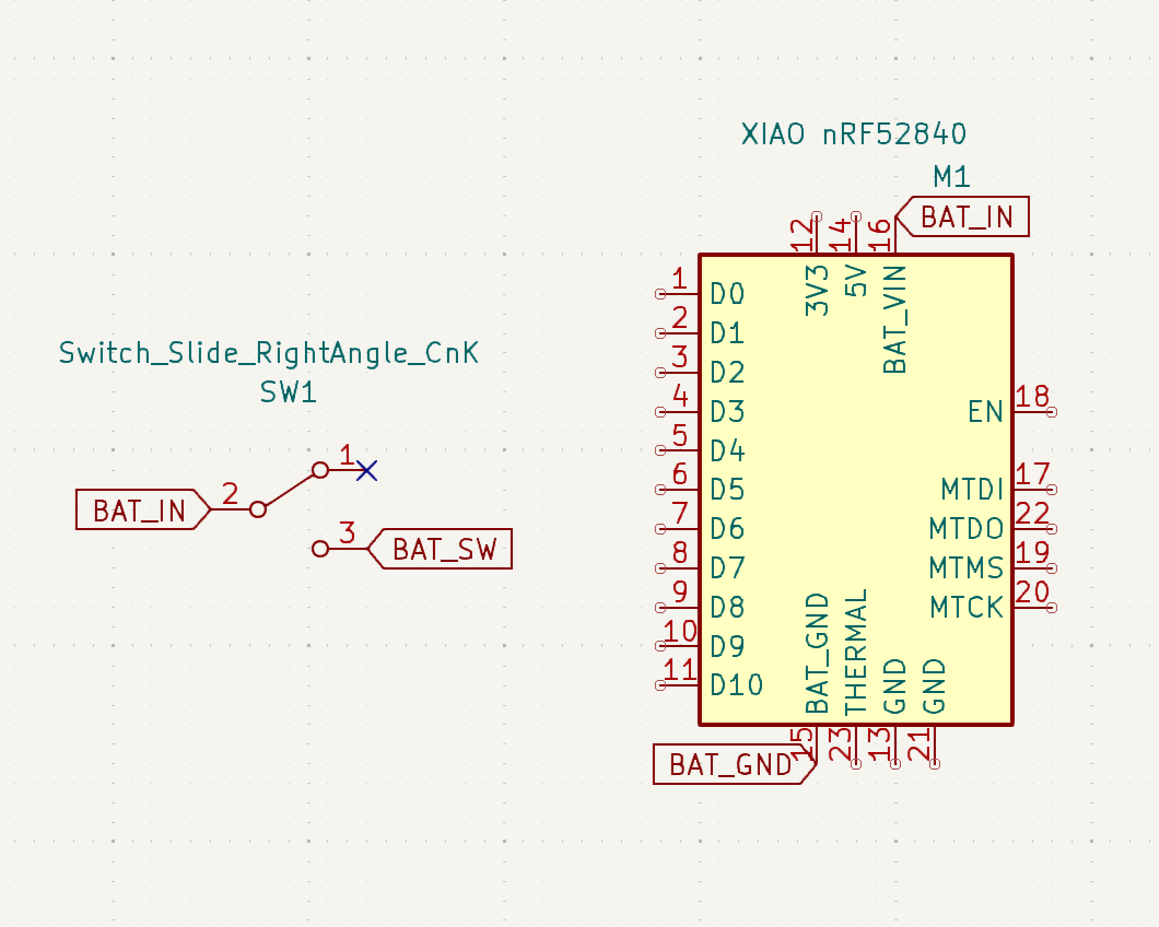
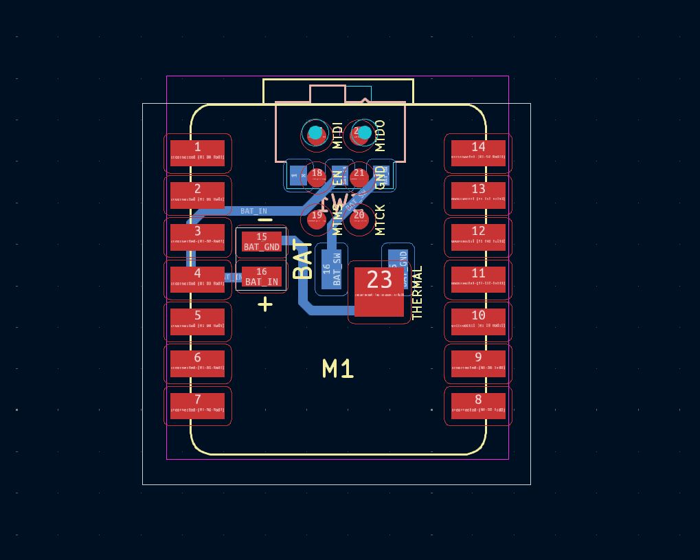
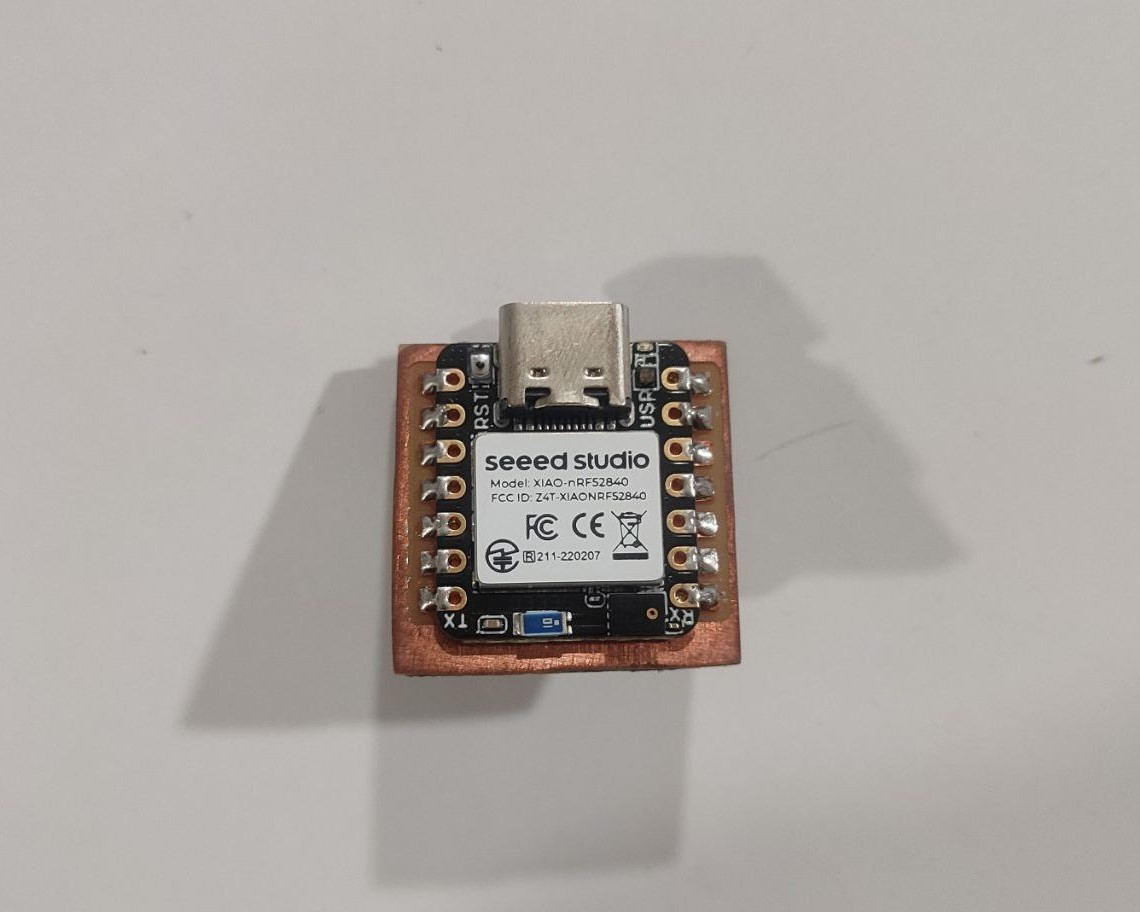
• PCB for Dice
The dice is made using Seeed Studio XIAO nRF52840 Sense. For it to be rechargable, 3.7 LiPo battery has to be provided and also a sliding switch to switch it off so that the battery doesn't drain unnessecarily. Both the Type C connector of the XIAO and the sliding switch should be accessible from the outside but should not project out so that it doesn't affect the normal working of the dice.
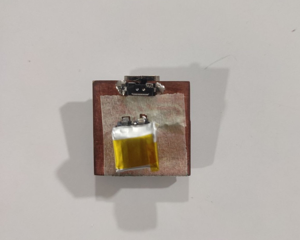
I checked if the PCB along with the battery are working by uploading a simple blink code and removing the serial connection.
Design & Manufacturing
Dice
Once the PCB was completed, I started with the outer shell design. The constraints were that it should be compact, the Type C connector as well as the sliding switch should be accessible from outside. My design is inspired from a dice I saw on Pinterest. The dice should hold the PCB in place, i.e., it should not have any tilt or move its position while the dice is being rolled.
A slot was provided to insert the PCB and keep it in place. Since, the other side is vacant, there is a chance of improper weight balance which may impact the roll. Hence, a solid infill of 5% was given.
The first idea was to 3D print the dice in double colour as seen in the design using Bambu Labs. But it failed twice because the white portion was too thin and it doesn't hold well with the rest of the body.
Hence, I decided to print the whole dice in white and then use black vinyl cut stickers to show the numbers. I created offsets to the design and took out the dxf and then imported it in Inkscape to get the SVG file for Vinyl Cutting.
Once everything was ready, I assembled the dice.
Game Board
The next are the parts I designed for the Flip Mechanism. Design and the 3D printed parts are mentioned above.
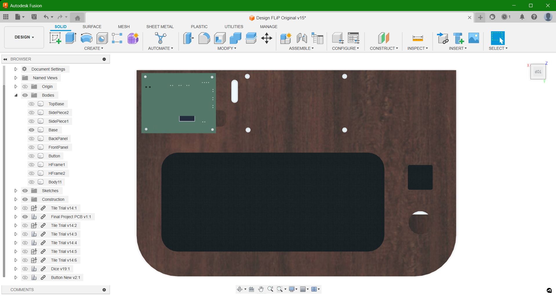
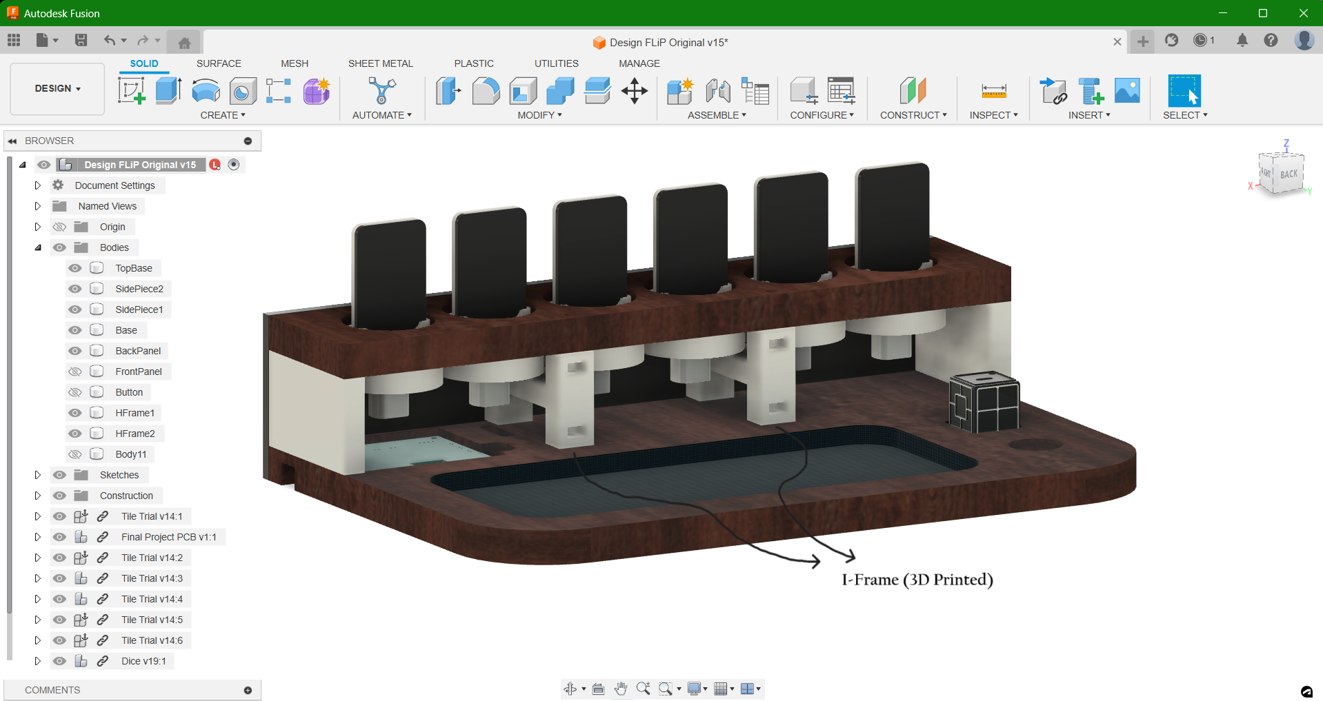
The main design is for the Game board itself. It houses the PCBs and the 6 complete flip modules. The main PCB is placed at one of the edges so that the power jack can be accessed from outside.
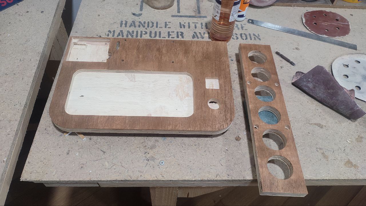
- The base of the board as well as the top base that holds the flip modules are plywood milled using Zund Digital Cutter.
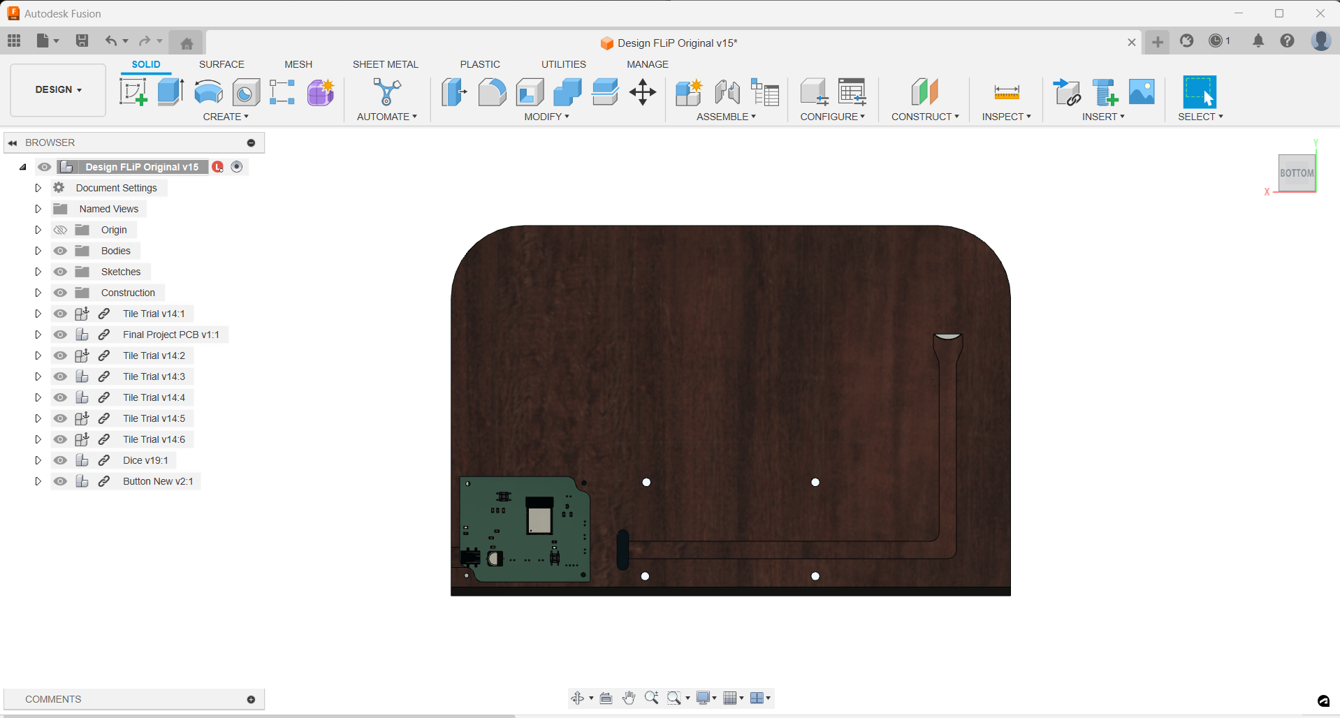
- The bottom side of the base has a pocket that connects from the position of button to the main PCB.
- Hole has been provided at the side where the button will be held so that the wires could pass through it.
- Two I-Frame 3D printed structures were placed inside for stability.
- I stained the plywood bit.
- The button is 3D printed in clear PLA filament. But once printed, it wasn't much clear which actually helped to disperse the light from neopixel.
- The front, side and back panels were laser cut. The front panel is connected to the top base with the help of two M4 counter-sunk screws. The side panels were glued in.
- The main PCB board is placed upside down so that the JST Connectors can be connected properly.
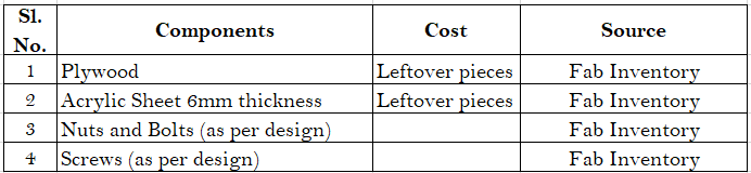
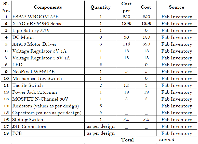
Materials and Components used, its cost and source?
• Material List
• Electrical and Electronics Components
Assembly
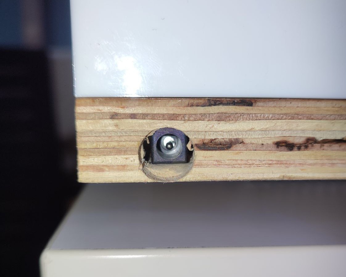
Manually drilled a hole on the side corresponding to the power jack's position.
Here's how the inside looks after connecting all the wires to the motors and the other PCB.
.jpg)
.jpg)
Programming
What Can the Code Do?
- When the board is powered, the tiles rotate and comes into a fixed position: 1 to 3 will be black and rest will be white.
- Next bluetooth communication is to be established between the dice and the board.
- The neopixel will blink in yellow if connection not established.
- The neopixel will lit up in green if connection established.
- Long press on the button to start the game.
- Player 1 is blue and Player 2 is red.
- Task of Player 1 is to make all the tiles face white.
- Task of Player 2 is to make all the tiles face black.
- If no possible combinations are there, the chance is automatically skipped.
- If only 1 combination is there, it is automatically flipped.
- If there is more than 1 combinations, green along with the player's colour blinks.
- Single press on the button shows each combinations. Lifting the dice fixes the chosen combination and light changes to opponent's colour to indicate their chance.
- Once a player wins, it showcases a visual cue to celebrate the winner's success.
- The tiles then go back to its initial position.
Here's Thej's celebration and FLiP's visual cue when she won!
My instructor, Jogin, helped me come up with the final codes. The codes are available to be downloaded from below.
Presentation Slide
Presentation Video
Gratitude Note
I want to take a moment to express my deepest gratitude to Super Fab Lab Kochi. The environment the lab provided was incredibly inspiring and really nurtured my creativity and learning. I would like to extend my heartfelt thanks to everyone who has helped me in the creation of FLiP.
A special shout-out to my amazing instructors, Saheen, Jogin, and Mufeed. Your patience, knowledge, and dedication made all the difference in my journey. I'm truly grateful for the time and effort they put into helping me grow.
I also want to thank all my fab mates. Their support, camaraderie, and collaboration made the experience so much more enriching. Working alongside such a talented and enthusiastic group was both inspiring and rewarding.
Download Files
• 3D Design File (.f3z file)• DXF Files for Laser Cut (zip file)
• Vinyl Stickers for Dice (.svg file)
• PCB Design & Gerber Files (zip file)
• Programming Codes (zip file)