Output Devices
Objectives for Week 9
- Add an output device to the microcontroller board we have designed and program it to do something
- Group Assignment: Measure the power consumption of an output device
This week I thought of starting with the basics for my Final Project. The project consists of a board on which the game pieces or the tokens are controlled using CNC XY table whose primary output device is Stepper Motor. So for this week I am designing and creating a new PCB that can help run a stepper motor.
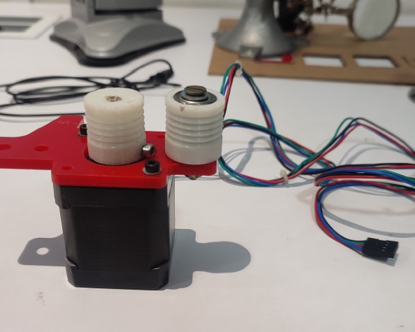
NEMA 17 Stepper Motor
In our FabLab, we have two kinds of stepper motor: 28BYJ-48 and NEMA 17. After a brief discussion with my instructor, Saheen, I planned to use NEMA 17 because I got to know that the other motor is quite slow compared to NEMA 17.
Features of NEMA 17 Stepper Motor
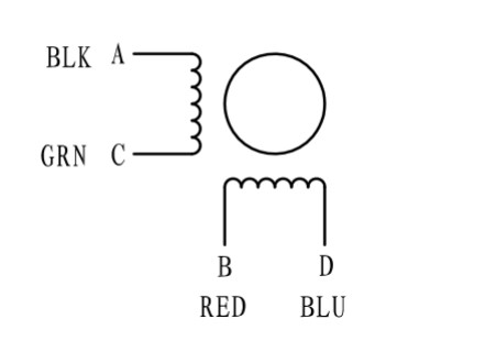
- 2 phase motor with bipolar configuration
- Requires a driver that can reverse the current direction to achieve motion.
- It has a step angle of 1.8 degrees, which translates to 200 steps per full revolution contributing to precise control of movements
- The holding torque varies from 12 N.cm to over 50 N.cm. Holding torque is a critical factor since it determines the maximum load the motor can handle without losing position when stationary.
Biploar and Unipolar
      NEMA 17 stepper motors can be designed as either bipolar or unipolar:
      • Bipolar motors have two coils (or two groups of coils) and require a change in the direction of current flow to change the magnetic field polarity, typically requiring more complex driving circuits like H-bridges.
      • Unipolar motors have an additional tap in the middle of each winding, allowing simpler driving circuits but often resulting in lower torque for the same size motor.

      The motor I am using is having bipolar configuration with 4 leads.
DRV8825
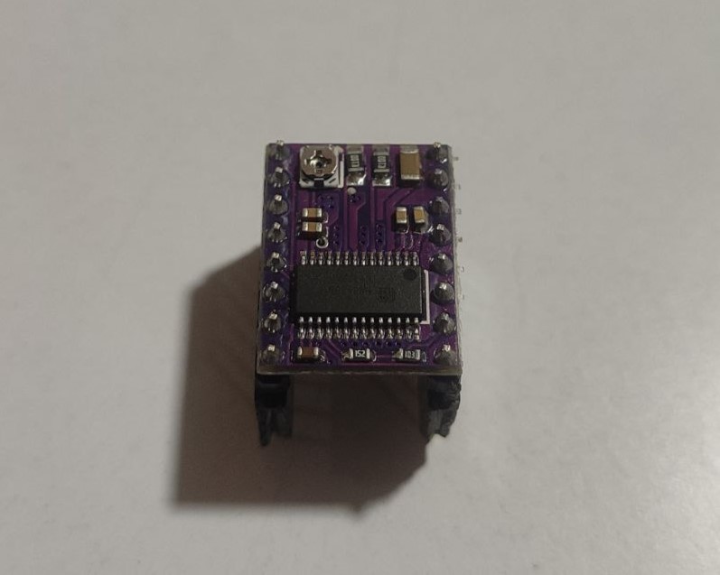
The motor driver can provide higher output power, more accurate output current voltage, frequency control, more precise position control, and higher efficiency.
DRV8825 is a propular choice for controlling NEMA 17 because of the following reasons:
- It can handle motor supply voltages up to 45V and can deliver up to approximately 2.5A per phase (1.5A without overheating). This range is suitable for NEMA 17.
- It supports adjustable current limiting and offers up to 1/32-step microstepping. Microstepping allows for smoother motor motion, higher step resolution, and reduced mechanical resonance, which are crucial for applications that demand precise motion control and low vibration.
- Includes features like thermal shutdown, under-voltage lockout, and crossover-current protection.
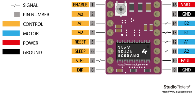
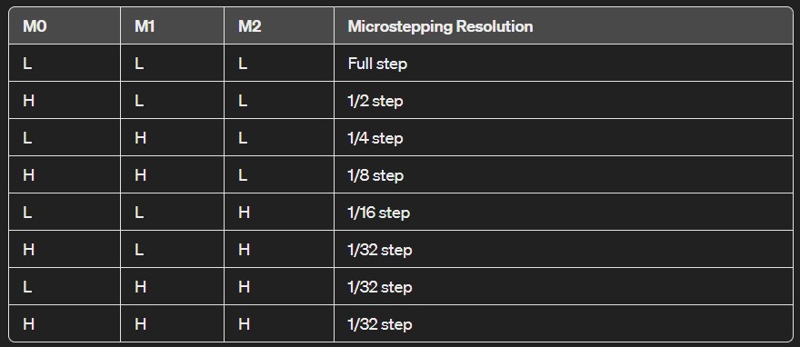
- It offers improved performance compared to some other drivers, such as the A4988, in terms of driving capability and heat dissipation. The microstepping resolution of the DRV8825 is configured by setting the logic levels of three pins: M0, M1, and M2. The combination of these pins' states (high or low) determines the microstepping mode.
Microstepping
Microstepping is a method used in stepper motor control that allows a motor to make finer steps than its basic step size, leading to smoother motion, reduced resonance, and increased positional accuracy. The DRV8825 stepper motor driver supports microstepping up to 1/32 steps.
The DRV8825 achieves microstepping by proportionally controlling the current in the two coils of the stepper motor. The microstepping resolution of the DRV8825 is configured by setting the logic levels of three pins: M0, M1, and M2. The combination of these pins' states (high or low) determines the microstepping mode.
Refer Last Minute Engineers to know more about the driver module.
ATtiny1614
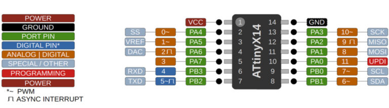
At first thought, I wanted to create a separate PCB with the driver module that can be compatible with the SAMD11C14A board I have created last week. But my instructor suggested I try using a different microcontroller. During the past weeks, I have tried using XIAO RP2040 and SAMD11C14A, and for this week I used ATtiny1614.
Features of ATtiny1614
- Utilizes the high-performance, low-power AVR RISC architecture.
- 16 KB of flash memory.
- Supports up to 20 MHz clock speed, providing a good balance between processing power and power consumption.
- Provides support for I2C, SPI, and UART communication, enabling the microcontroller to connect with a wide range of sensors, actuators, and other microcontrollers or microcomputers.
- Includes high-resolution timers and multiple PWM channels for precise control over timing and output modulation, suitable for tasks ranging from simple time-keeping to complex motor control.
- ATtiny1614 can be programmed via UPDI (Unified Program and Debug Interface), simplifying the development process with only a single wire for programming and debugging.
PCB Design
During 'Electronics Design' week, I was introduced to KiCad to design PCBs. So I used the same tool this week. The first task is to identify the required components apart from the driver and the microcontroller. Once that was done, I started with the schematic diagram.
I started off with designing a board just for the driver module thinking that I could use the microcontroller board I have created last week for the purpose. Here's the PCB I had designed.
I converted the gerber files to png files using Gerber Viewer. Refer the documentation of Week 8 to know how I did it. Once I got the files, I milled the PCB. But soon enough I realized my mistake.
The footprint for the driver module I used was through-hole. So, in order to solder the pins, the module has to be inserted from the bottom side, thereby, the footprint had to be flipped during the design process and I had forgotten to do so. Hence, I had to edit the design again.
And this is when my instructor suggested I create an entirely new board with an ATtiny1614 microcontroller. And I did so. I was hesitant at first as this meant the number of components will be larger and the thought of routing all these components made me weak at the knees😣. But then I thought I'll give it a chance as anyway I have to create new boards for my upcoming weeks and final project and this would be an added experience.
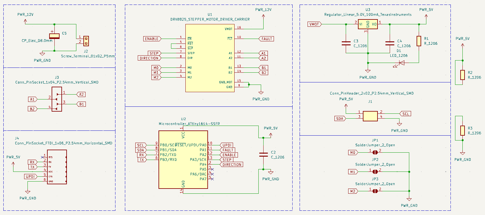
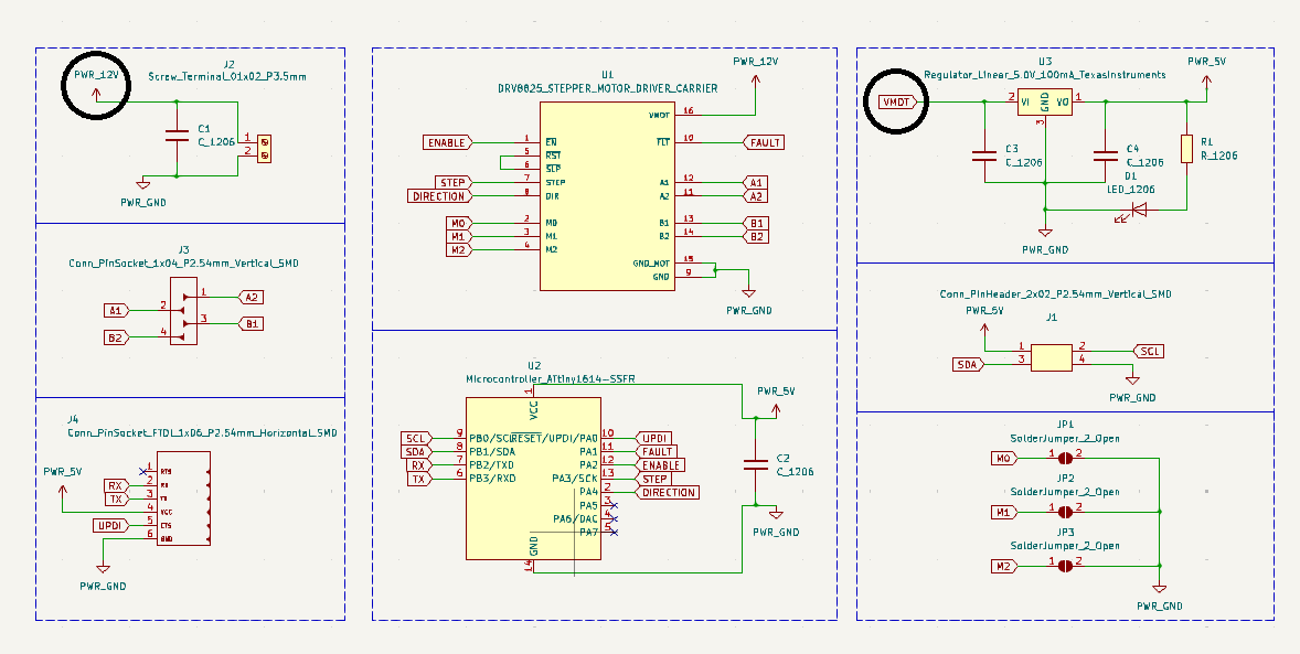
I made the schematic diagram with all the required components.
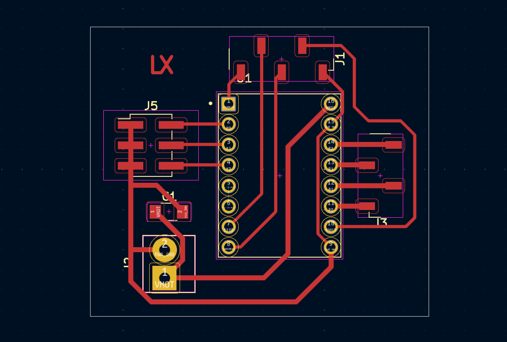
Once I completed the schematic, since the driver was through-hole, I designed a new footprint for the driver making it SMD so that I can connect them using headers.
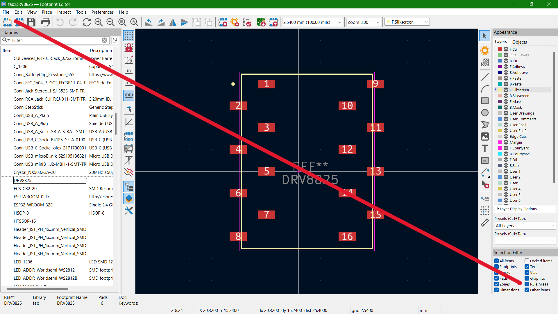
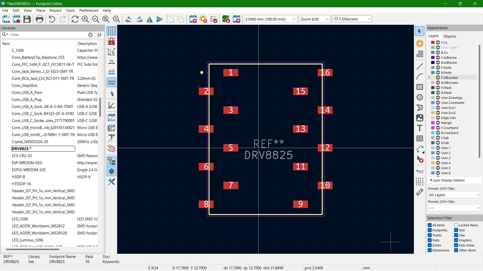
But while programming I realized a major mistake in my footprint created. I gave the pin numbers in wrong order, and it was too late so I had to modify the board I had milled with cuts and jumpers. The corrected footprint is available to download at the end of this documentation.
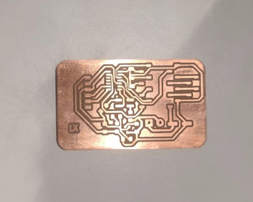
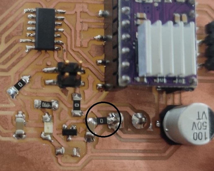
It took me more than 5 hours this time to route all the traces. I wanted it to be single side so no to jumpers. Instead, Midhun, my fellow mate at FabAcademy suggested I use 0 ohm resistors to cross at those places where I find it really difficult to connect the power lines. Here's how it looked after routing.
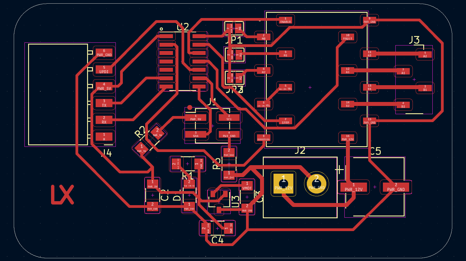
I used Gerber Viewer to convert the gerber files to png files and I proceeded to milling.
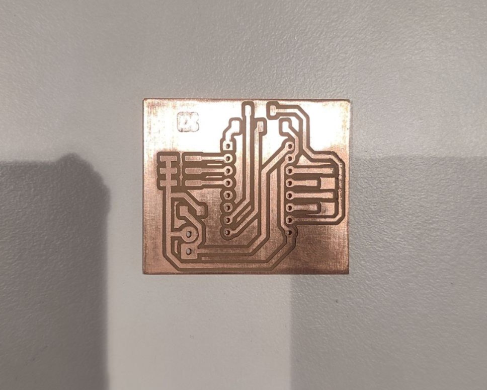
PCB Milling
The next step is milling the PCB. I am using Roland Modela MDX20 along with MODs for the purpose. I already have some experience in using both during Electronics Production and Electronics Design weeks.
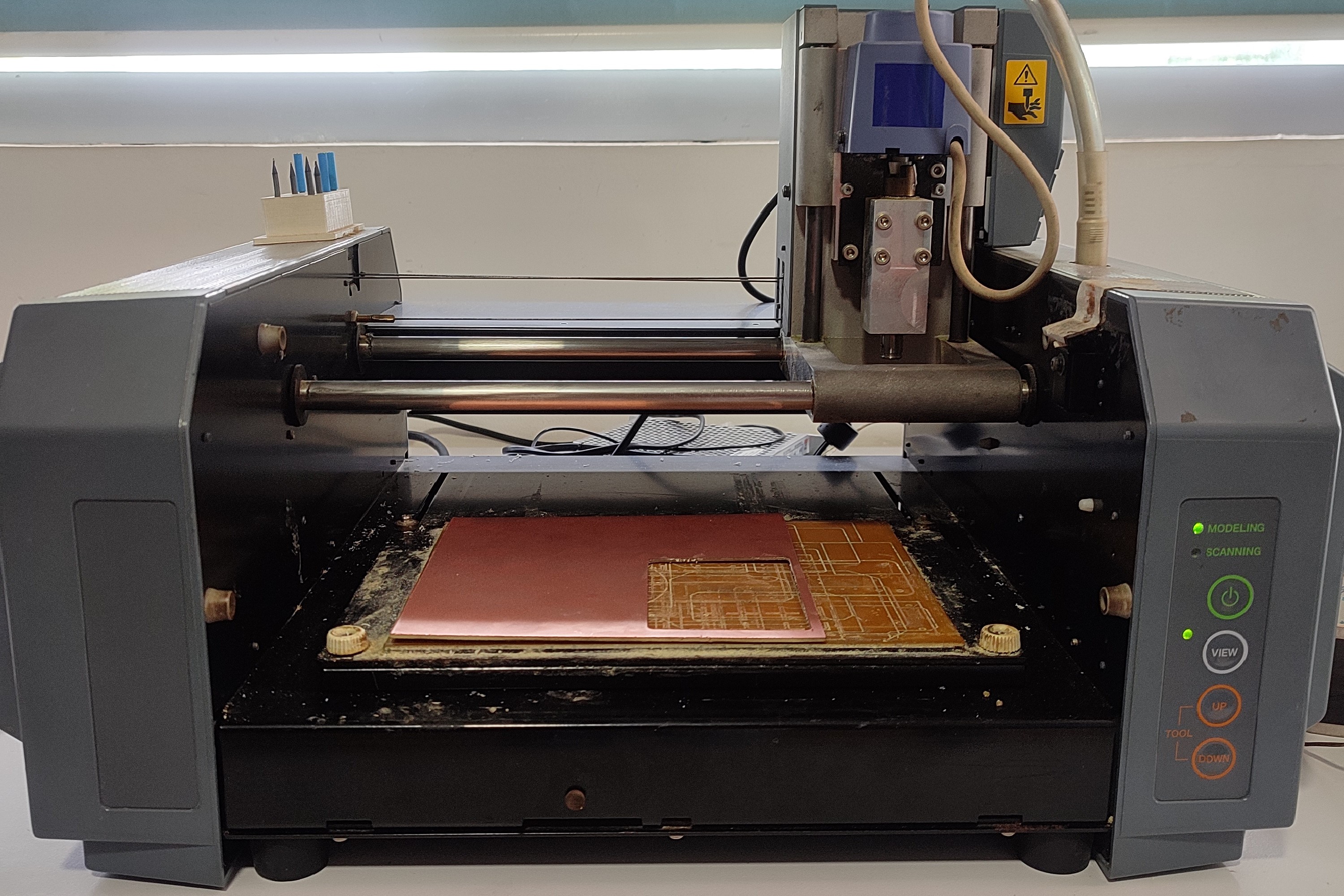
Refer documentation of Week 4 to know about the working processes of Roland Modela MDX20 and MODs.
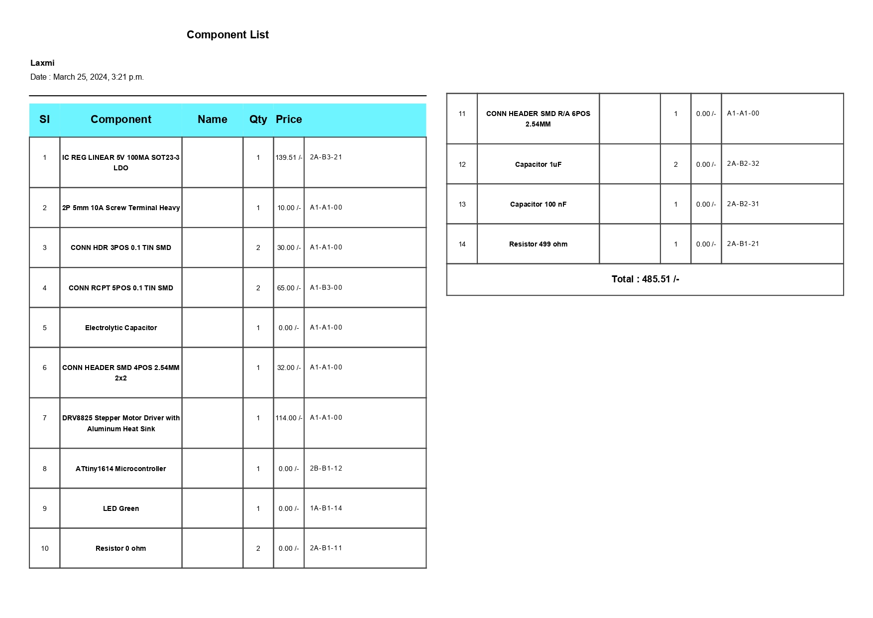
The next step is to request for the required components from Fab Inventory. The component list is as below:
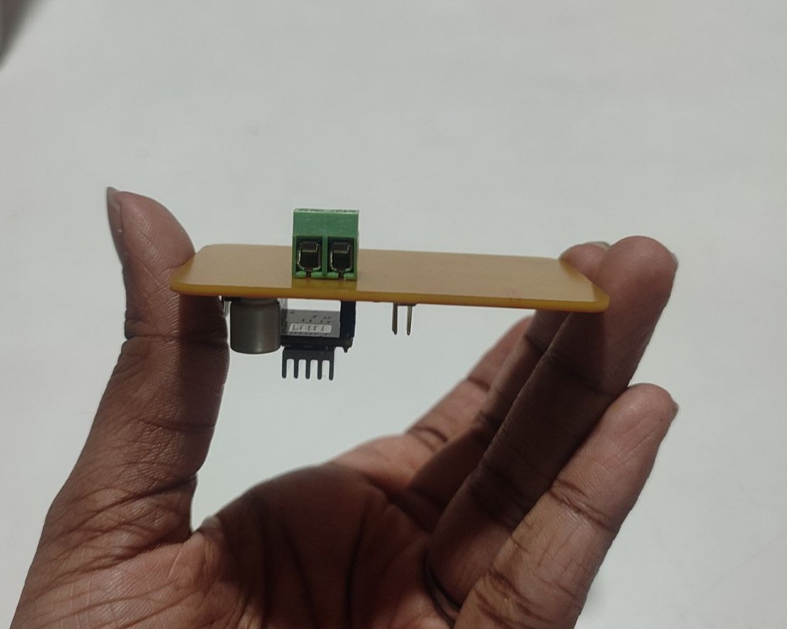
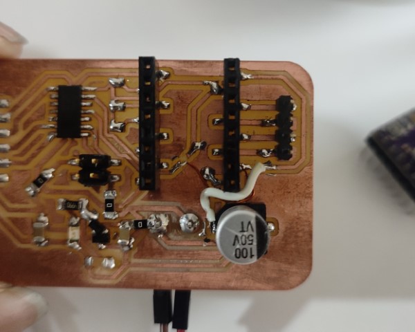
Then I started soldering the components to the board and this is how it finally turned out.
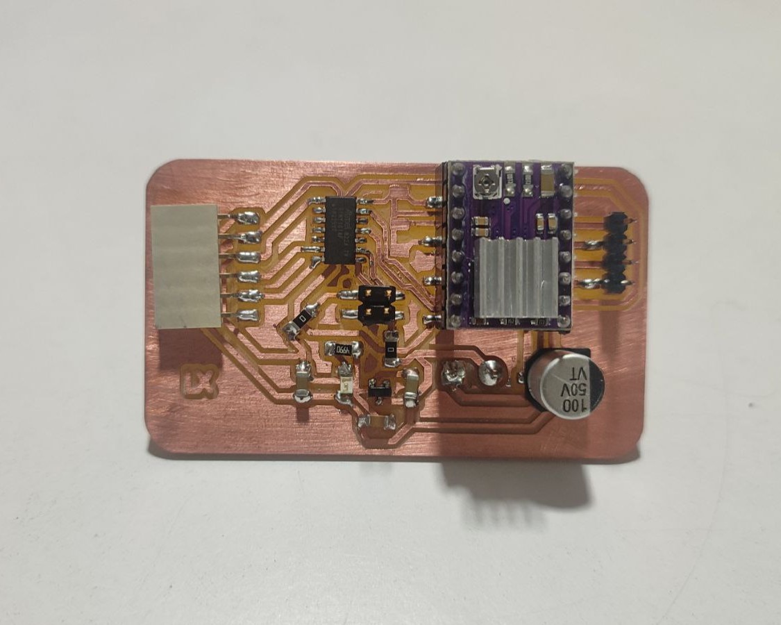
In case of microstepping, later I soldered all the three jumpers and therefore achieving full step.
Programming
I used Arduino IDE for the code. I took a sample code to run the stepper motor in both clockwise and counter-clockwise direction from Last Minute Engineers and modified it to my requirements. Here's the modified code:
// defines pins
#define stepPin 10 //referred from ATtiny1614 Pinout Diagram
#define dirPin 0 //referred from ATtiny1614 Pinout Diagram
#define faultPin 8 //referred from ATtiny1614 Pinout Diagram
#define enablePin 9 //referred from ATtiny1614 Pinout Diagram

void setup() {
  // Sets the pins as Outputs
  pinMode(stepPin,OUTPUT);
  pinMode(dirPin,OUTPUT);
  pinMode(faultPin,OUTPUT);
  pinMode(enablePin,OUTPUT);
}
void loop() {
  digitalWrite(dirPin,HIGH); // Enables the motor to move in a particular direction
  digitalWrite(enablePin,LOW); // DRV8825 driver is enabled when the pin is LOW
   digitalWrite(faultPin,HIGH); // If FAULT pin is LOW, chip is disabled
  // Makes 200 pulses for making one full cycle rotation
  for(int x = 0; x < 800; x++) {
    digitalWrite(stepPin,HIGH);
    delayMicroseconds(700);    // by changing this time delay between the steps we can change the rotation speed
    digitalWrite(stepPin,LOW);
    delayMicroseconds(700);
  }
  delay(1000); // One second delay

  digitalWrite(dirPin,LOW); //Changes the rotations direction
  // Makes 400 pulses for making two full cycle rotation
  for(int x = 0; x < 1600; x++) {
    digitalWrite(stepPin,HIGH);
    delayMicroseconds(500);
    digitalWrite(stepPin,LOW);
    delayMicroseconds(500);
  }
  delay(1000);
}
Once the code was ready, the next step is to add the code to the board. Since, the ATtiny board cannot be directly connected to the system, I used the Quentorres board as a programmer. I followed the link below to set up everything in Arduino.
https://wolles-elektronikkiste.de/en/using-megatinycoreI took the URL:"http://drazzy.com/package_drazzy.com_index.json" provided in the site and pasted it on "Additional Boards Manager URLs" from File > Preferences
Then I downloaded a package from Boards Manager.
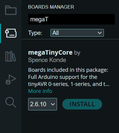
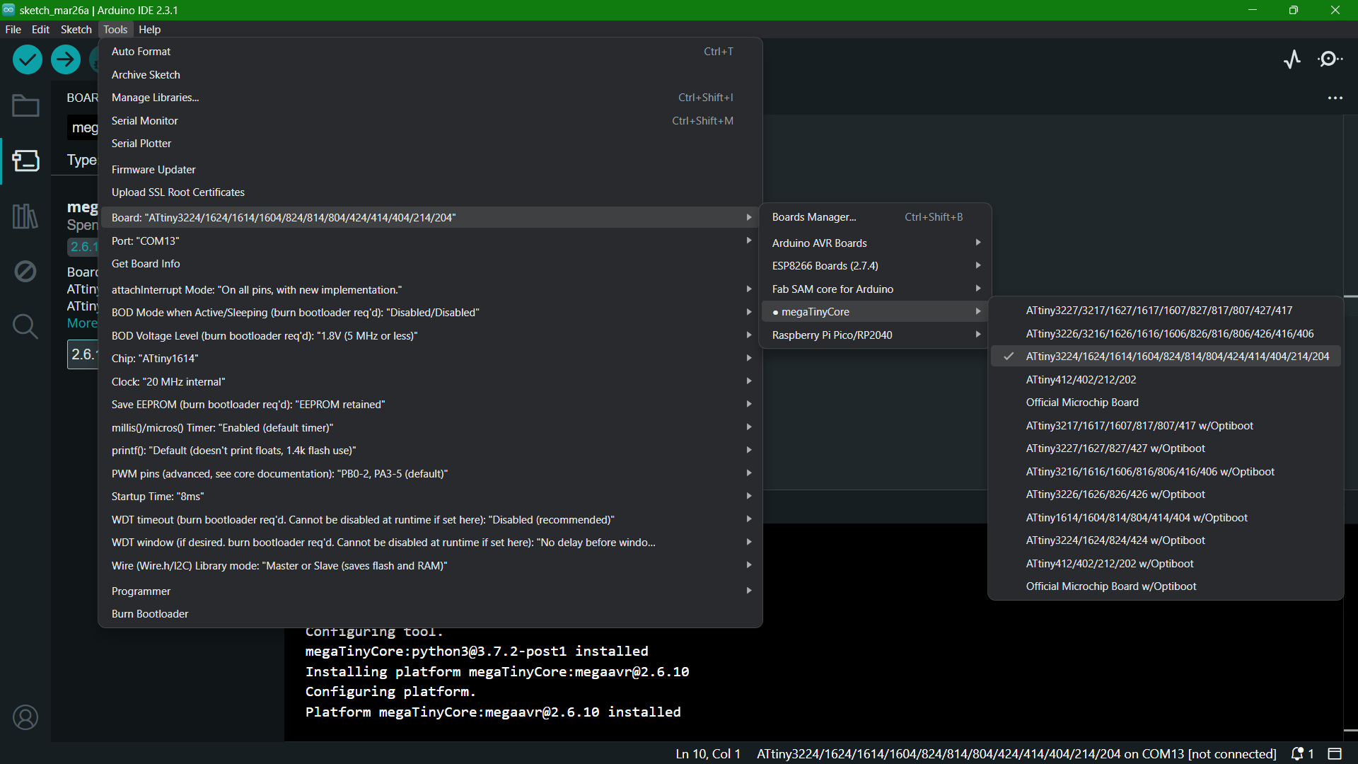
Once the package is downloaded, click on Tools > Board Manager > megaTinyCore > ATtiny3224/1624/1614/1604/824/814...
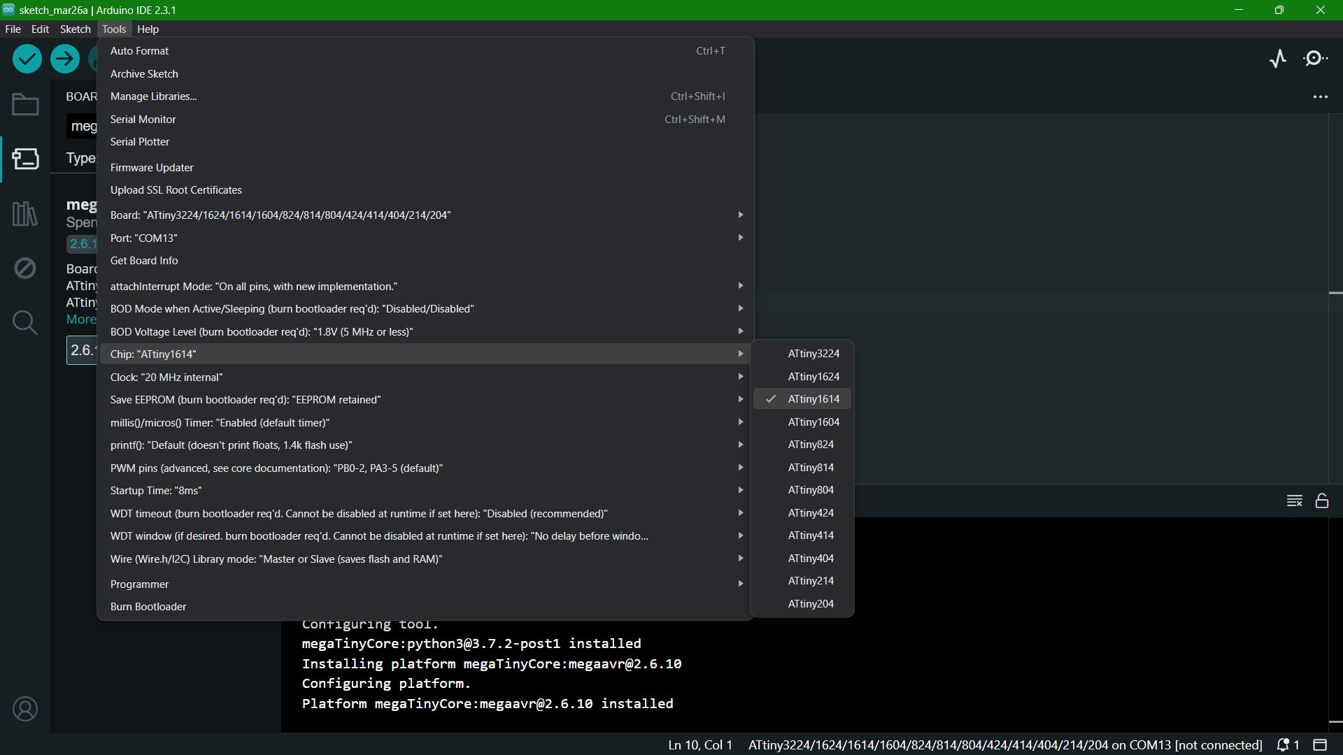
Next select the chip, Tools > Chip > ATtiny1614
Select the programmer as SerialUPDI - SLOW: 57600 baud
.png)
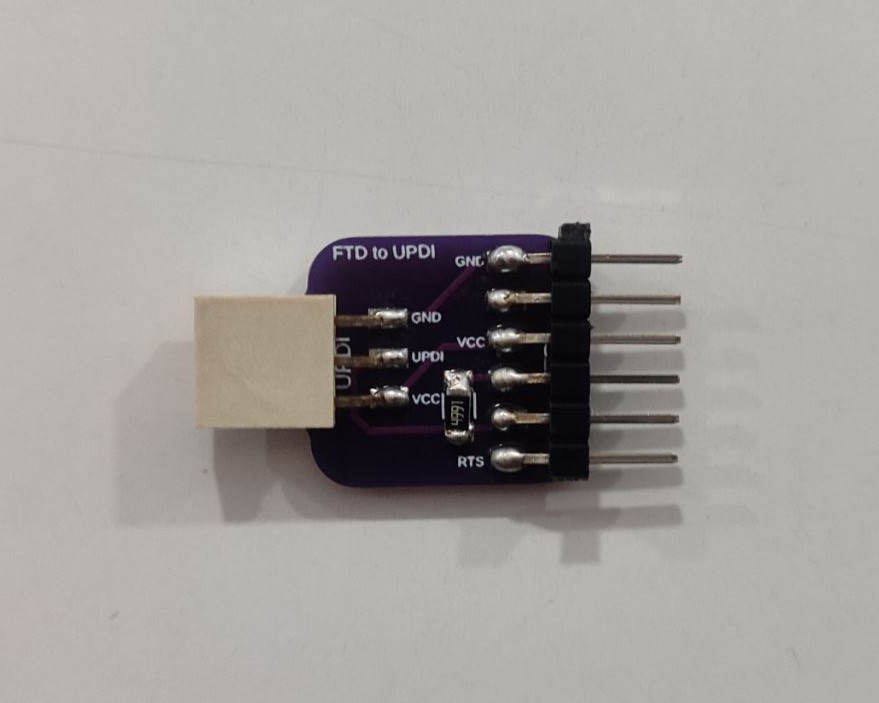
The next step is to connect the new board to the Quentorres then to the system. Quentorres doesn't have UPDI pin so we are using a FTD to UPDI convertor we have here at FabLab in between.
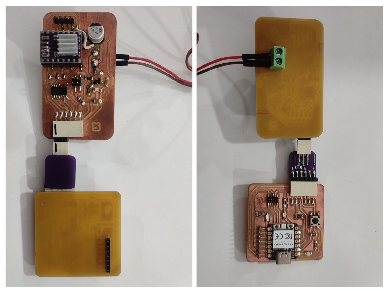
Then I connected it to the system, selected the port and click on Burn Bootloader.
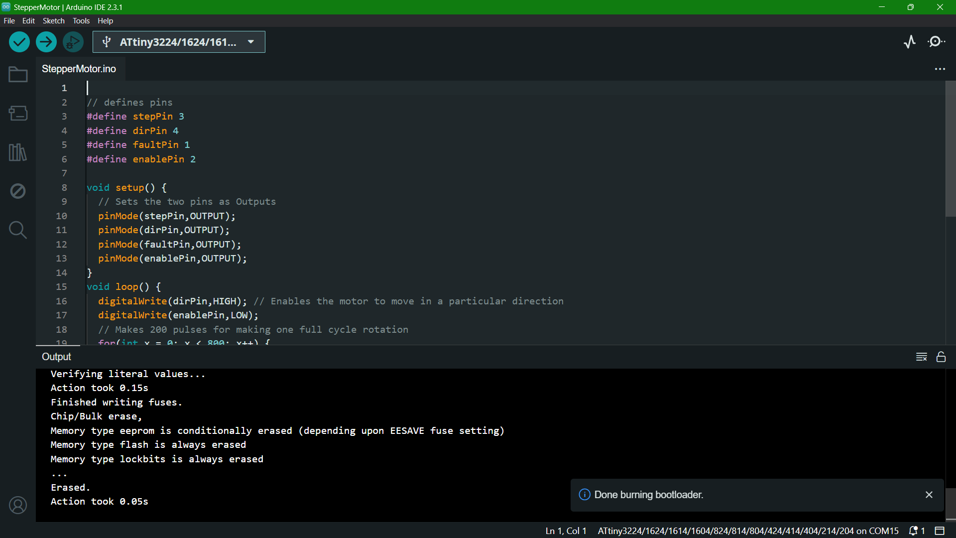
Once completed, I uploaded the code to the board.
Running the Stepper Motor
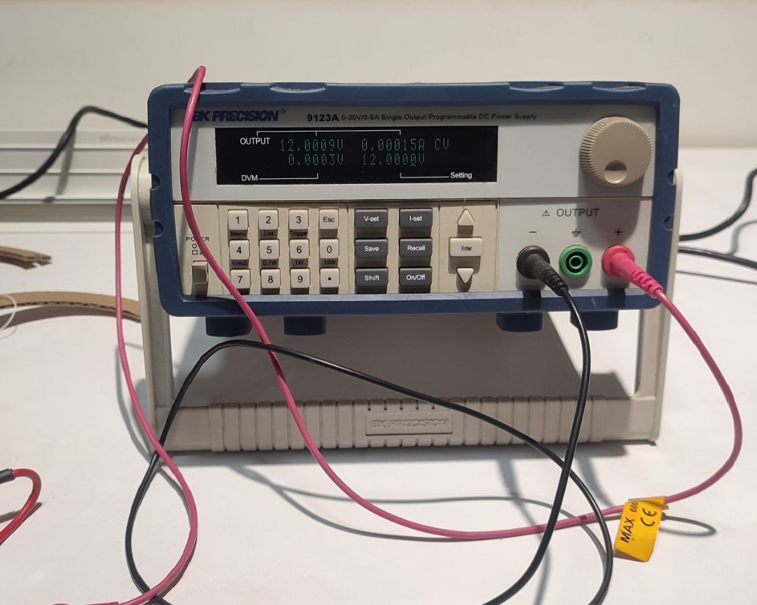
I screwed in two wires at the terminal and connected it to DC Power Supply.
  Parameter values set on DC Power Supply
  Voltage: 12V
  Current: 0.5A (To check if it's shot)
Current Limiting Potentiometer
Before running the motor, we must limit the maximum current flowing through the stepper coils so that it does not exceed the motor’s rated current. This is done by tightenening or loosening the screw which actually is a current limiting potentiometer. Here, I have set its voltage at around 0.6V.
Refer Last Minute Engineers to know about the two methods in which the adjustment can be done.
Mistakes and Problems faced this week
- I had to design the PCB again as I forgot to flip the driver module so as to solder. (in through-hole case)
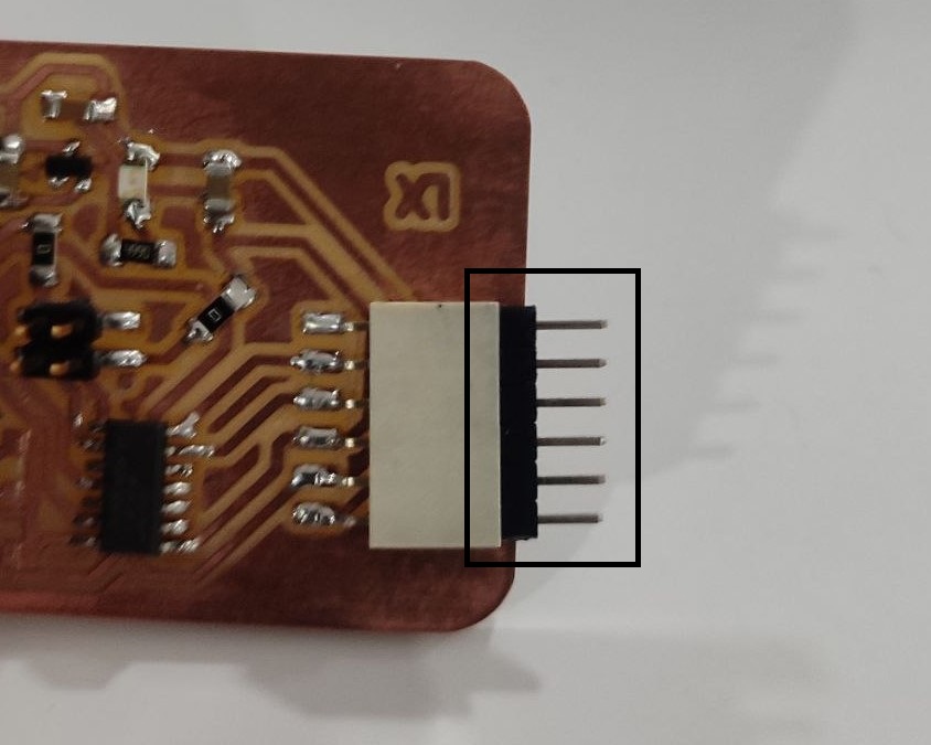
- It is while soldering the components that I noticed the position of the FTDI. It was supposed to be at the edge but while providing the edge cut without realizing, I gave space in between.
- The distance between the solder jumper was too small that the machine wasn't able to cut it.
- I forgot to change the name under one of the label connecting to the 12V power line.
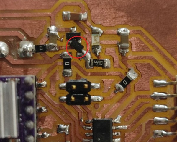
- While connecting to the system once soldered, the voltage regulator was heating up.
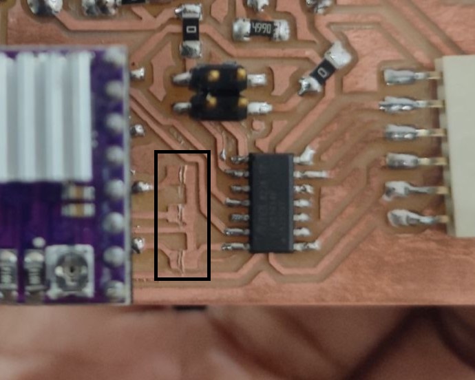
- I gave the wrong pin number order for the footprint I had created for DRV8825.
- As the current increases, the power consumption also increases proportionally.
- The graph provides specific data points that show how power consumption changes under different conditions (without motor, with motor, base setting, and with load).
Solution: Made a new footprint making the DRV8825 as SMD instead of through-hole.
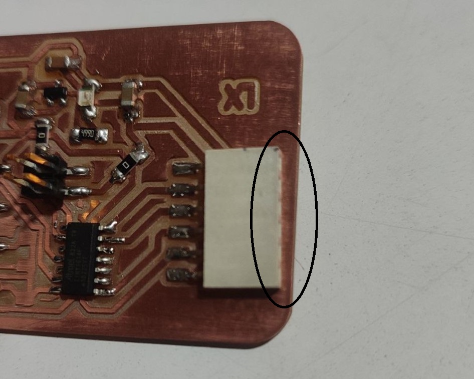
Solution: Used a connector pin.
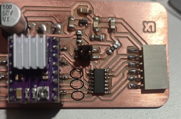
Solution: Manually made the cuts in between solder jumper.
Solution: Used a 0 ohm resistor to connect the lines.
Solution: Manually cut the voltage regulator 5V output and added a Schottky diode of 150mA 100v in between.
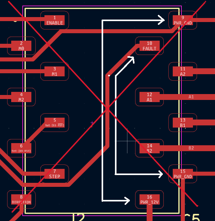
Solution: Cuts and jumpers were given in order to correct the path.
Group Assignment
This week's group assingment was to measure the power consumption of an output device. We chose Stepper Motor as the output device.
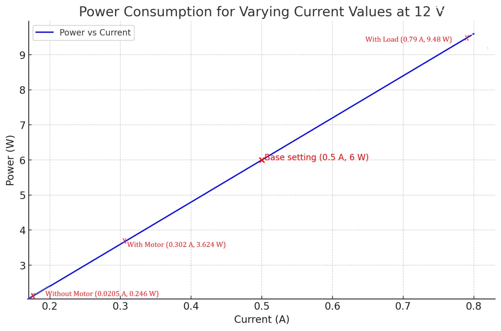
The graph illustrates the power consumption for varying current values at a constant voltage of 12V. The blue line represents the relationship between power and current. Power is calculated using the formula 𝑃=𝑉 𝐼, where 𝑉 is the voltage (12V in this case) and 𝐼 is the current.
In summary, the graph provides valuable insights into the power requirements of the system under different operational scenarios, enabling better design, optimization, and maintenance strategies.
For further details, click on the link below.
Group Assignment-Week 9Download Files
Design Files
• Top Traces (Main PCB) png file
• Top Drills (Main PCB) png file
• Edge Cut (Main PCB) png file

Footprint
• DRV8825 SMD Footprint

Program Code
• Stepper Motor (Arduino Code)