Networking and Communication
The assignments for this week:
- Group assignment :
- send a message between two projects
- Individual assignment:
- design, build, and connect wired or wireless node(s) with network or bus addresses and local input &/or output device(s)
What is networking and communication in electronics?
Network communication in electronics refers to the exchange of data between electronic devices over a network. This communication can occur through various methods and protocols, depending on the specific requirements of the application. In modern communication, wireless transmission of received serial data is provided by the RF transmitter at the rate of 1Kbps to 10Kbps. While the transmitted data is received by the RF receiver. The operating frequency range of the RF transmitter and RF receiver is the same. The NRF24L01 is one of the wireless transceiver RF modules used for SPI communication with a 2Mbps transmission speed.
About the NRF24L01
The NRF24L01 is a small device that allows different electronic gadgets to talk to each other wirelessly using radio waves.It is a wireless transceiver RF module, where each module can send and receive data. Since it operates on the 2.4 GHz ISM band, the technology is approved for engineering applications in almost all countries. This module can cover 100 meters when operated efficiently, making it suitable for wireless remote control projects. Some of the key features are:Radio Communication: It uses radio waves to send and receive data, similar to how walkie-talkies work.
Low Power: It doesn't use much power, making it great for battery-powered devices.
Fast Data Transfer: It can send data quickly, up to 2 million bits per second.
Multiple Channels: It has many channels to use, so multiple devices can talk without interfering with each other.
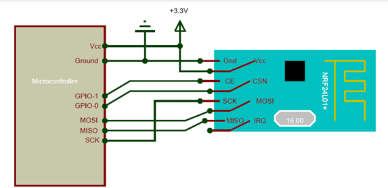
Easy Connection: It connects to microcontrollers through a simple communication method called SPI.
The NRF24L01 module is powered by 3.3 Volts, so it can be easily used in both 3.2 Volts and 5 Volts systems. Each module has an address range of 125 to communicate with the other 6 modules and also allows several wireless units to communicate with each other in a specified location. Therefore, mesh and other types of networks use this module. NRF24L01 is a radio transceiver module (SPI protocol) used to send and receive data at ISM operating frequency from 2.4 to 2.5 GHz.
Operating Modes
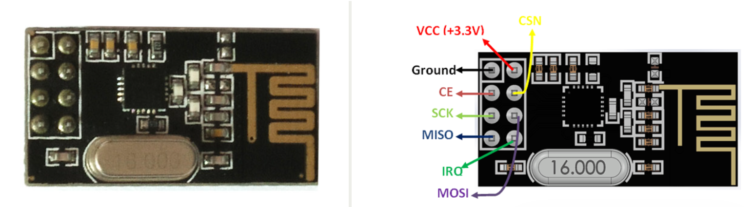
It operates in 3 modes, which are transmitter mode, receiver mode, and transceiver (transmitter and receiver) mode. So, these modes are discussed below. In transmitting mode, when the power is 0dBm, then the NRF24L01 uses only 11.3mA current. While in receiving mode, it uses only 13.5mA current. In the transceiver mode, the NRF24L01 module is used for long-distance and quick transmission of data using the SPI protocol.Pin configuration
VCC: Power supply (1.9V to 3.6V, typically 3.3V).GND: Ground.
CE (Chip Enable): Used to switch between transmit and receive modes.
CSN (Chip Select Not): Used to activate the SPI interface.
SCK (Serial Clock): Clock for SPI communication.
MOSI (Master Out Slave In): Data line for SPI communication.
MISO (Master In Slave Out): Data line for SPI communication.
IRQ (Interrupt Request): Optional pin for handling interrupts.
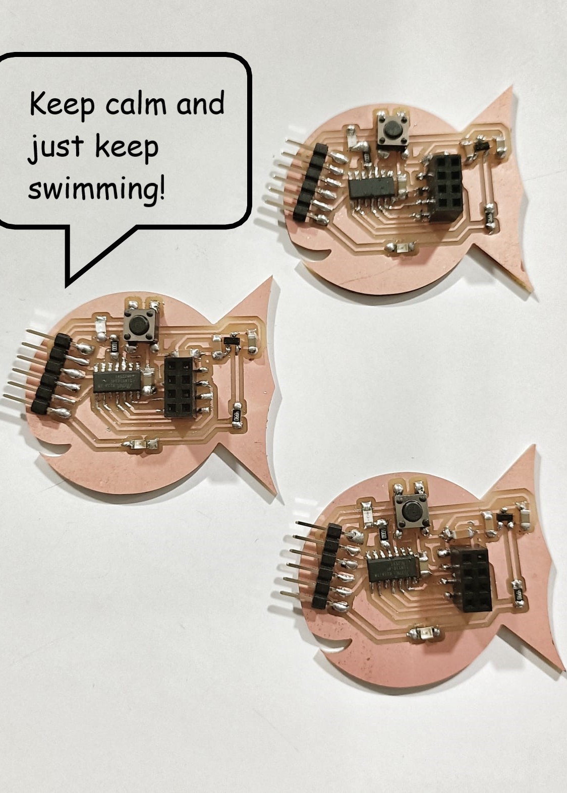
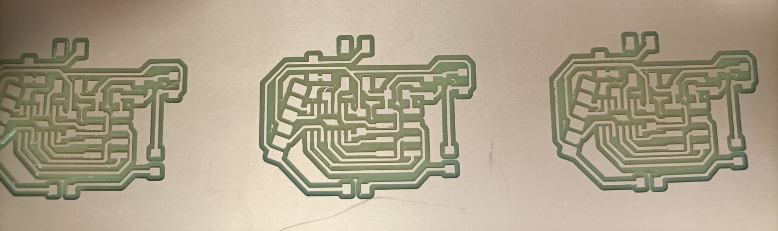
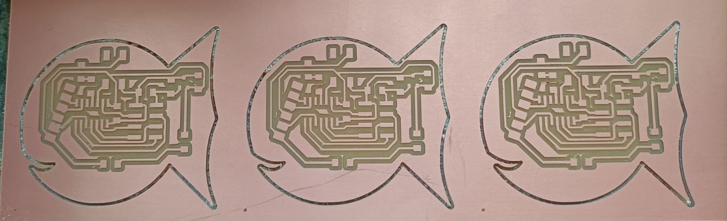
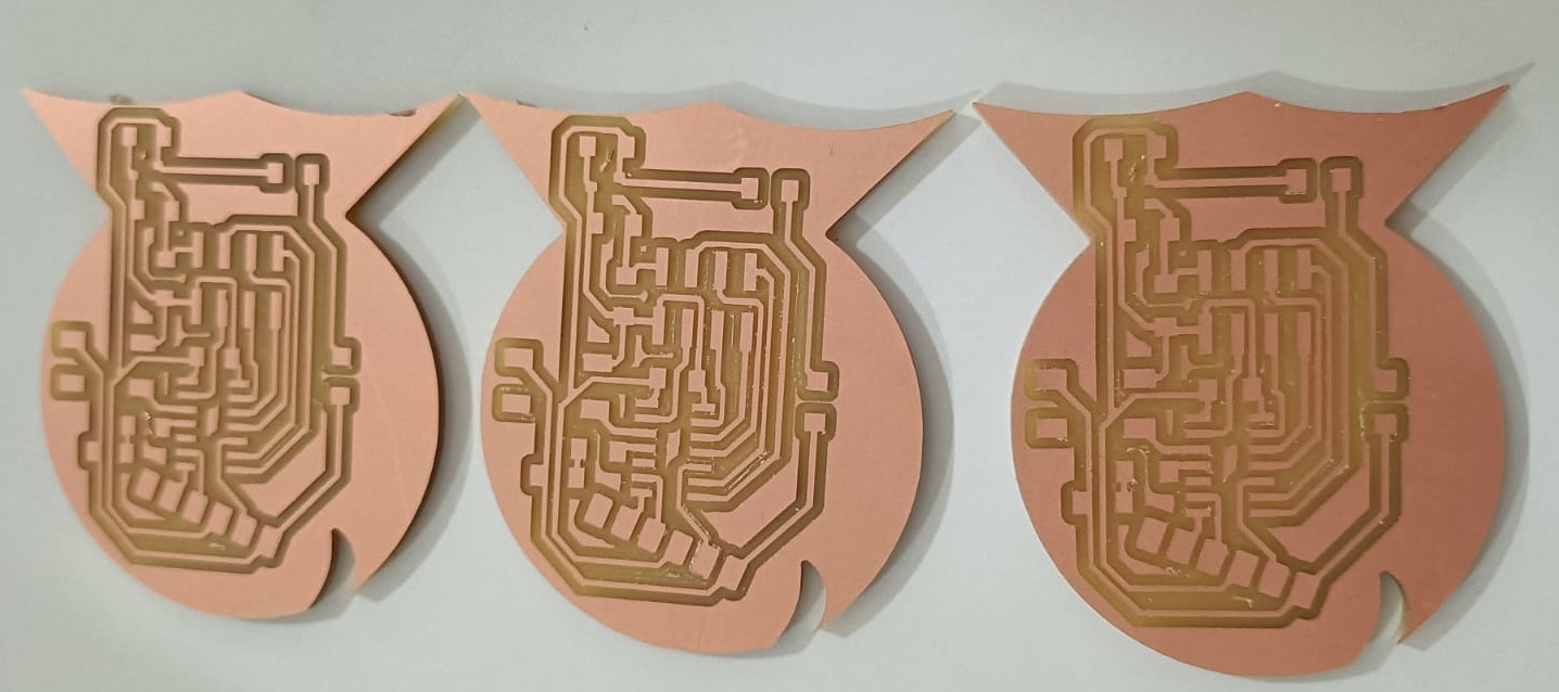
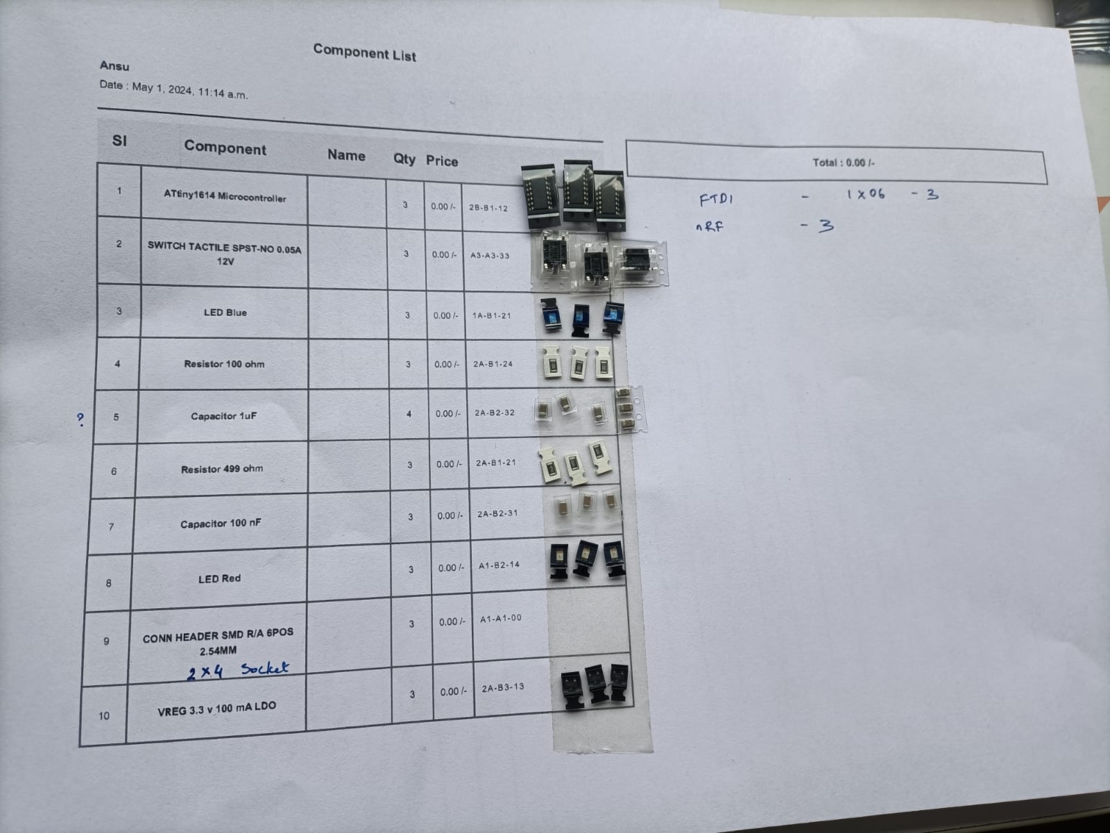
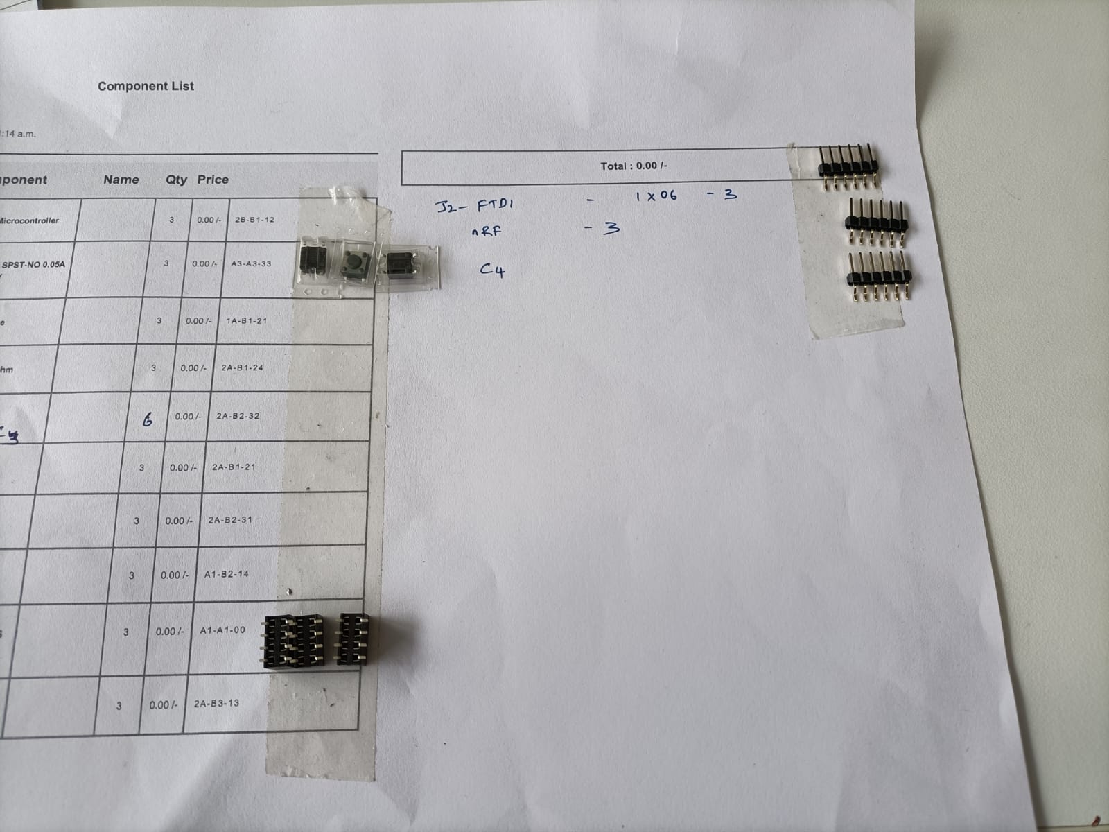
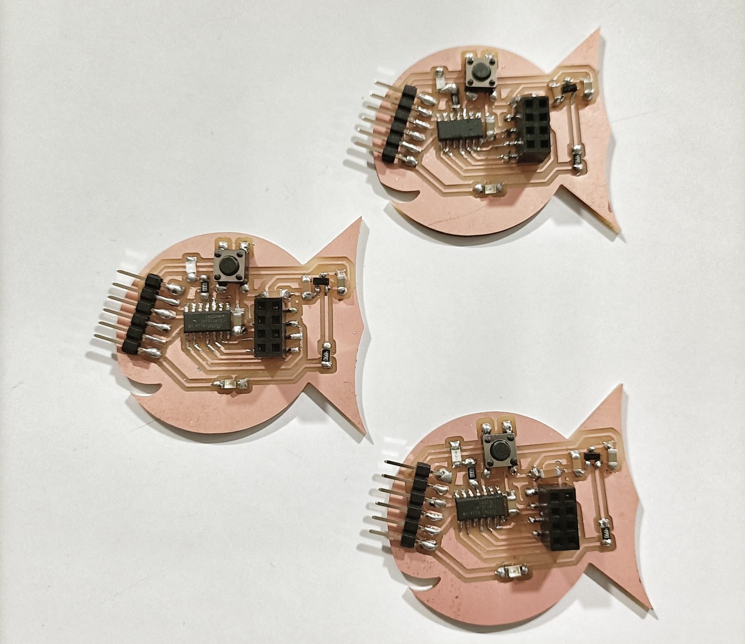
PCB Design
The microcontroller I used here is the Attiny1614. I created three boards. Since the nRF24L01 transceiver module operates at 3.3V, I included a voltage regulator and a button is connected to trigger the nRF24L01 transceiver module.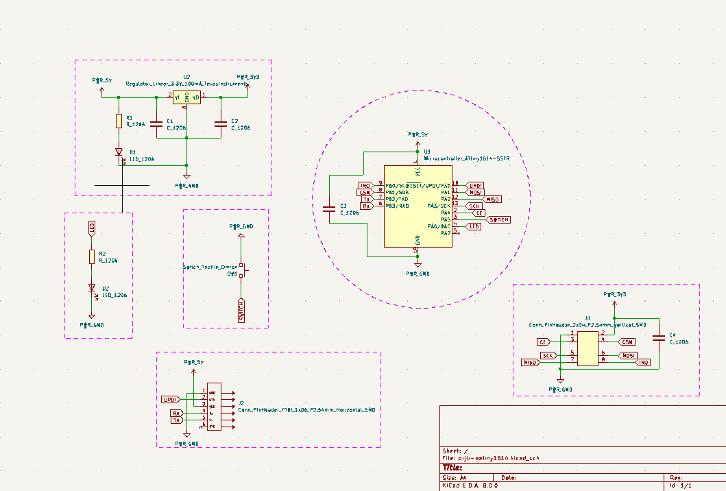
I milled the three identical boards.
Communication between two boards
Considering one of the boards as a transmitter, I uploaded the program below. The second board is considered as the receiver and the corresponding program (the second one below) is uploaded to it.These codes enable wireless communication between two nRF24L01 modules. The transmitter sends the message "Hello World" every second to a specified address. The receiver listens on the same address and prints any received message to the serial monitor. When the transmitter is connected the receiver gets the 'Hello World' message. For these codes, I referred Praveen Kumar's Fabacademy pageNRF24L01 as an SPI Transmitter
The code for this is from here.
      // transmitter Include Libraries

      #include < SPI.h>
      #include < nRF24L01.h>
      #include  < RF24.h>

      //create an RF24 object
      RF24 radio(0, 6);  // CE, CSN

      //address through which two modules communicate.
      const byte address[6] = "00001";

      void setup()
      {
        radio.begin();

        //set the address
        radio.openWritingPipe(00001);

        //Set module as transmitter
        radio.stopListening();
      }
      void loop()
      {
        //Send message to receiver
        const char text[] = "Hello World";
        radio.write(&text, sizeof(text));

        delay(1000);
      }
NRF24L01 as an SPI Receiver
The code for this is from here.
      //receiver Include Libraries
      #include < SPI.h>
      #include < nRF24L01.h>
      #include < RF24.h>

      //create an RF24 object
      RF24 radio(0, 6);  // CE, CSN

      //address through which two modules communicate.
      const byte address[6] = "00001";

      void setup()
      {
        while (!Serial);
          Serial.begin(9600);

        radio.begin();

        //set the address
        radio.openReadingPipe(0, 00001);

        //Set module as receiver
        radio.startListening();
      }

      void loop()
      {
        //Read the data if available in buffer
        if (radio.available())
        {
          char text[32] = {0};
          radio.read(&text, sizeof(text));
          Serial.println(text);
        }
      }
The video showing the communication is below.
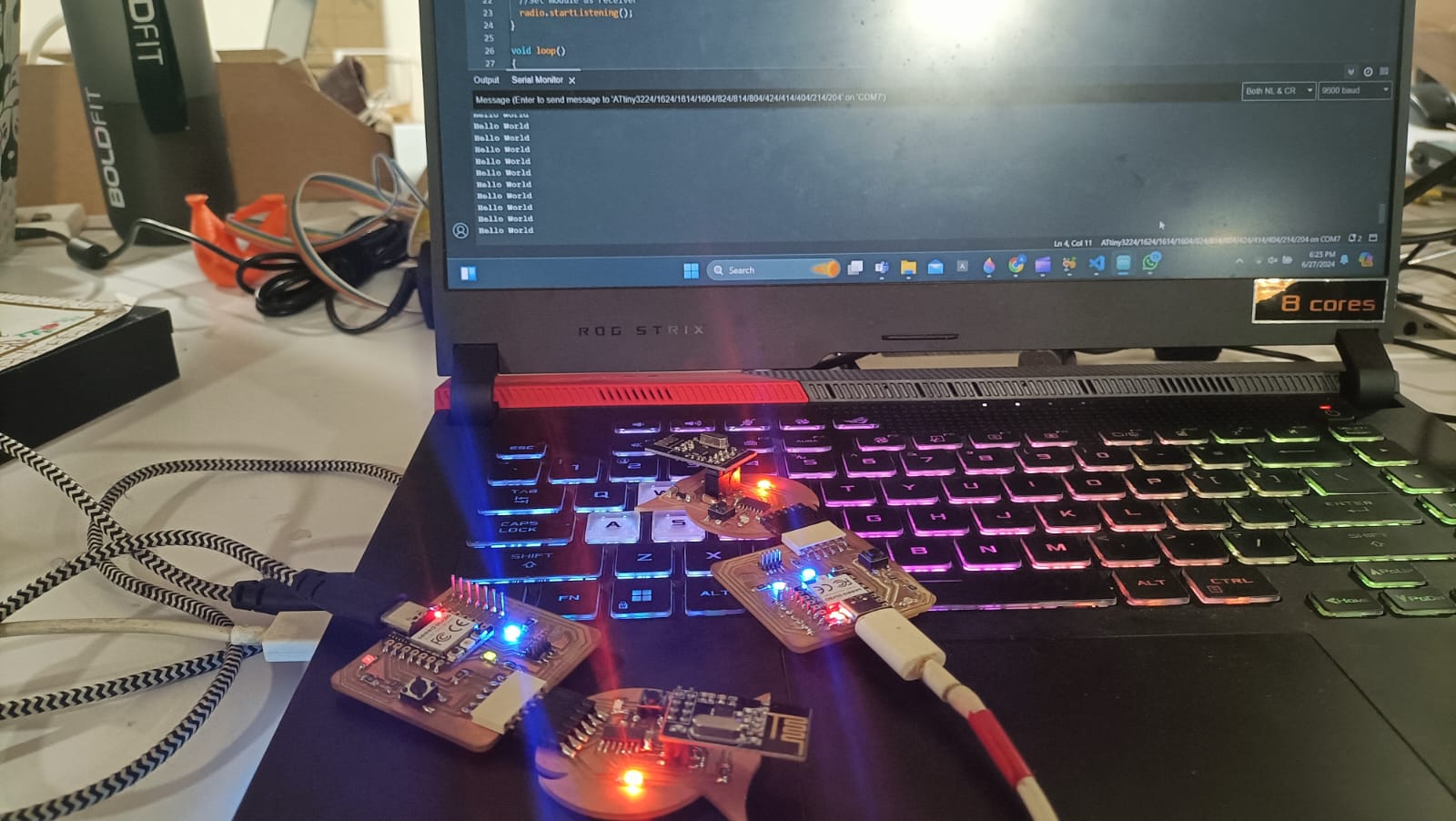
Communication between the three boards
This program implements a simple wireless communication system using an nRF24L01 transceiver module to control LEDs on different nodes based on button presses.Here, the program allows a button press to cycle through three different nodes(1,2,3), toggling the LED on each node and updating their status wirelessly using the nRF24L01 transceiver modules.
  #define BUTTON_PIN 1  // the number of the pushbutton pin
#define LED_PIN 2     // the number of the LED pin

// transmitter Include Libraries

#include < SPI.h>
#include < nRF24L01.h>
#include < RF24.h>

//create an RF24 object
RF24 radio(0, 6);  // CE, CSN

//address through which two modules communicate.
const byte address1[6] = "00001";
const byte address2[6] = "00002";
const byte address3[6] = "00003";

const int nodeNumber = 3;       // modify the nodeNumber as per the node you program 1,2,3
const byte address[6] = "00003";  // modify the address as per the node you program "00001" , "00002", "00003"

bool node1LedStatus = false;
bool node2LedStatus = false;
bool node3LedStatus = false;


bool ledState = false;         // the current state of the LED
int buttonState;               // the current reading from the input pin
bool lastButtonState = false;  // the previous reading from the input pin

int counter = 1;

// the following variables are long because the time, measured in milliseconds,
// will quickly become a bigger number than can be stored in an int.
unsigned long lastDebounceTime = 0;  // the last time the output pin was toggled
unsigned long debounceDelay = 50;    // the debounce time; increase if the output flickers

void setup() {
  pinMode(BUTTON_PIN, INPUT_PULLUP);
  pinMode(LED_PIN, OUTPUT);
  Serial.begin(115200);
  // set initial LED state
  digitalWrite(LED_PIN, ledState);

  radio.begin();

  radio.openReadingPipe(0, address);
  radio.startListening();
}

void loop() {


  if (radio.available()) {

    char text[32] = {0};
    radio.read(&text, sizeof(text));
    String Data = String(text);
    Serial.println(Data);
    if ( Data == "ON") {
      ledState = true;
    }
    if (Data == "OFF") {
      ledState = false;
    }
  }


  // read the state of the switch into a local variable:
  int reading = digitalRead(BUTTON_PIN);

  // check to see if you just pressed the button
  // (i.e., the input went from LOW to HIGH), and you've waited long enough
  // since the last press to ignore any noise:

  // If the switch changed, due to noise or pressing:
  if (reading != lastButtonState) {
    // reset the debouncing timer
    lastDebounceTime = millis();
  }

  if ((millis() - lastDebounceTime) > debounceDelay) {
    // whatever the reading is at, it's been there for longer than the debounce
    // delay, so take it as the actual current state:

    // if the button state has changed:
    if (reading != buttonState) {
      buttonState = reading;

      // only toggle the LED if the new button state is HIGH
      if (buttonState == HIGH) {
        // Serial.println(counter);
        if (counter >= 4) {
          counter = 1;
        }
        if (counter == nodeNumber) {
          if(counter != 3)
          {
            counter++;
          }
          else
          {
            counter = 1;
          }

        }
        sendTrigger(counter);
        counter++;

        // ledState = !ledState;
      }
    }
  }


  // set the LED:
  digitalWrite(LED_PIN, ledState);

  // save the reading. Next time through the loop, it'll be the lastButtonState:
  lastButtonState = reading;
}


void sendTrigger(int nodeSelect) {

  bool triggerStatus = false;
  Serial.println(nodeSelect);
  switch (nodeSelect) {
    case 1:
      triggerStatus = node1LedStatus;
      node1LedStatus = !node1LedStatus;
      radio.openWritingPipe(address1);

      break;
    case 2:
      triggerStatus = node2LedStatus;
      node2LedStatus = !node2LedStatus;
      radio.openWritingPipe(address2);
      break;
    case 3:
      triggerStatus = node3LedStatus;
      node3LedStatus = !node3LedStatus;
      radio.openWritingPipe(address3);
      break;
  }

  radio.stopListening();

  if (triggerStatus) {

    char text[32] = "ON";
    radio.write(&text, sizeof(text));
    delay(100);
  } else {
    char text[32] = "OFF";
    radio.write(&text, sizeof(text));
    delay(100);
  }


  radio.openReadingPipe(0, address);

  radio.startListening();
}
In this program,
Group assignment:
Communication between two projects
.png)
Design files
NRF2401 as a receiverNRF2401 as a transmitter
Communicate between three boards