review the safety data sheets for each of your molding and casting materials,
then make and compare test casts with each of them
compare printing vs machining molds
Individual assignment:
design a mold around the process you'll be using,
produce it with a smooth surface finish,
and use it to cast parts
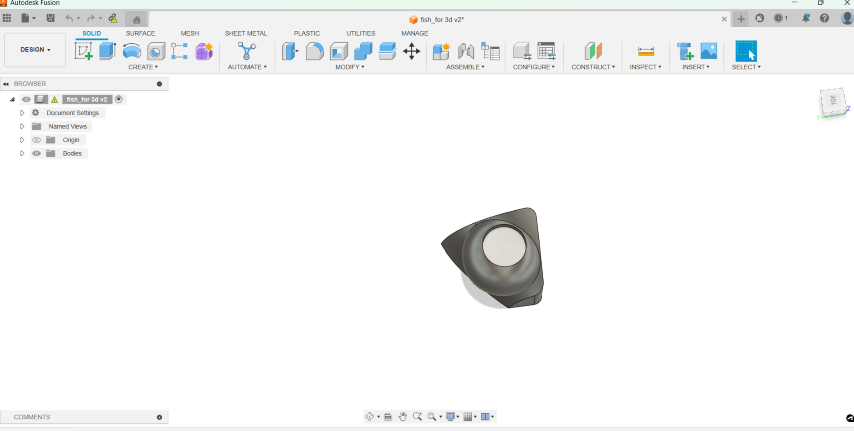
For this week, I planned to mould and cast a fish. To design, I used 'Create Form' and modified the quad ball to
get a fish.
I started by creating the main body of the fish. I selected a quadball and clicked on the workspace to place
the shape.
Once I placed the initial shape, I used the manipulation tools in the form environment to
sculpt it into the rough shape of a fish. I right clicked on the form and clicked 'edit form'
I refined the shape of the fish by adding detail and adjusting proportions.
I added a sphere for the eyes and a spline for the mouth, ensuring that the bit which is 3mm will be able to
make all the details done.
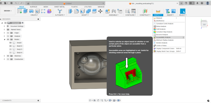
Once the design is done, the next step is to do the CAM. But before that, it is important to check the
accessibilty for the 3mm bit
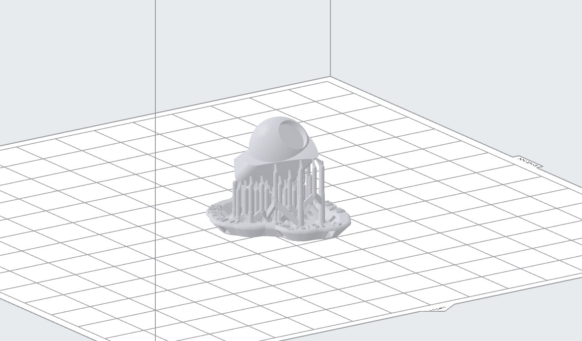
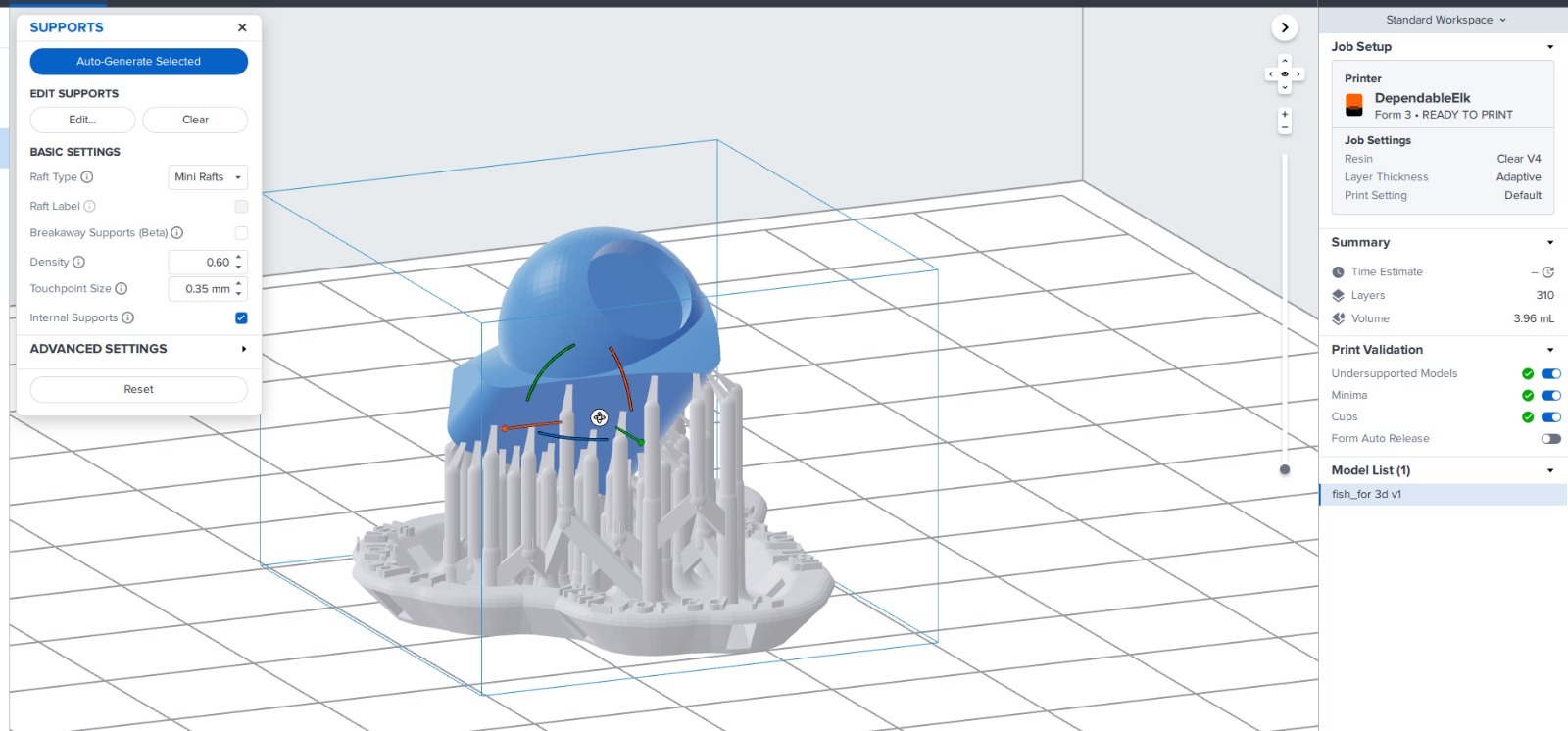
Since it is not possible to do under the eye, my friend, Amaljith helped me do the 3d print.
Cam
Computer-Aided Manufacturing (CAM) is a software technology used to generate toolpaths and instructions for
machining operations on CNC (Computer Numerical Control) machines. CAM software takes a 3D model of a part and
generates instructions (G-code) that control the movement of cutting tools to shape the material into the desired
form. In the context of making a mold, CAM software helps create toolpaths for machining operations that produce the
mold cavity.
I switched to the CAM workspace within Fusion 360, where I set up toolpaths for machining.
Then, I created a new setup for my part, defining the machining orientation and setup.
Next, I defined the stock material by selecting the part model or inputting the dimensions of the material I'm using.
Next, I selected the appropriate cutting tool, such as an end mill, suitable for my material and desired cutting parameters.
I configured cutting parameters like tool diameter, cutting depth, stepover, and spindle speed based on material and machining requirements.
I specified machining regions by selecting areas where material needs to be removed, typically the entire part geometry.
Then,I defined machining heights, including the top and bottom of the part, and any additional clearances or safety distances.
I chose the T3 Adaptive clearing operation from available CAM strategies.
Then,I fine-tuned operation settings like maximum roughing stepdown, optimal load, and cutting direction to suit my preferences and part requirements.
Before machining, I simulate the toolpath to ensure it efficiently clears material and avoids collisions.These are the toolpaths
for the different setups:
For the Adaptive using 6mm flat.
For the Adaptive using 3mm flat.
For the Adaptive using 3mm flat for the dents.
For the Adaptive using 3mm flat.
For the Adaptive using 3mm ball.
Once satisfied with the simulation, I generated the G-code necessary to run the machining process
I saved the CAM setup and G-code files to my computer or export them directly to TRAK DPM RX2 milling machine with an USB.
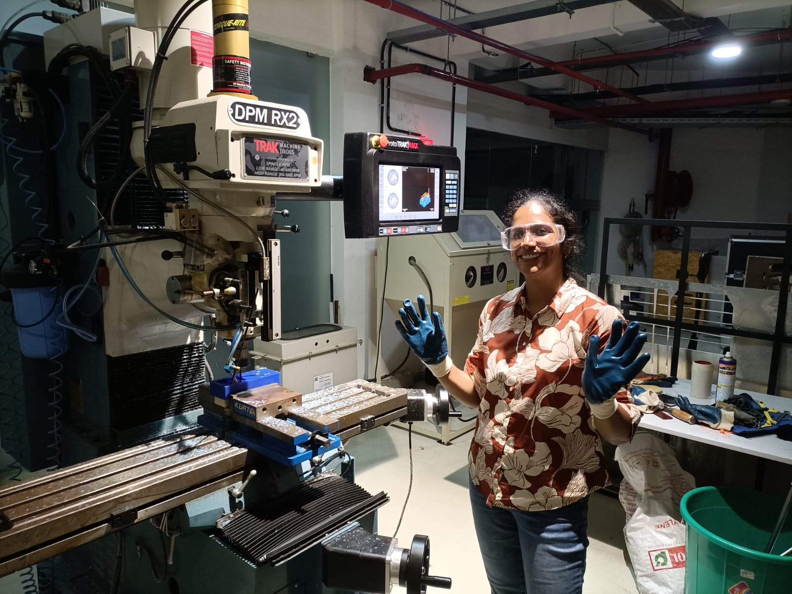
Machine setup
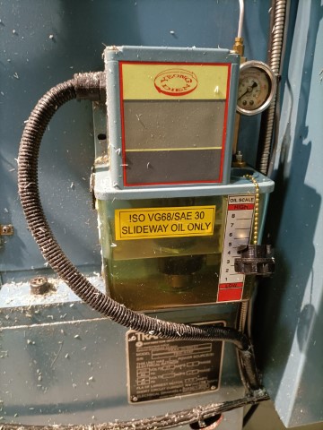
It's important to perform regular checks of the oil and coolant levels as part of your machine maintenance routine.
The frequency of these checks may vary depending on the usage of the machine and the manufacturer's recommendations.
Locate the oil reservoir on the TRAK DPM RX2 machine.If the oil level is low, add the appropriate type of oil
until it reaches the proper level.
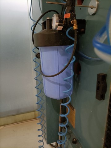
Check the coolant level visually. It should be at or slightly above the minimum level indicated on the
reservoir.
If the coolant level is low, add a mixture of coolant and water to the reservoir until it reaches the proper
level. The coolant mixture ratio should follow the manufacturer's recommendations.
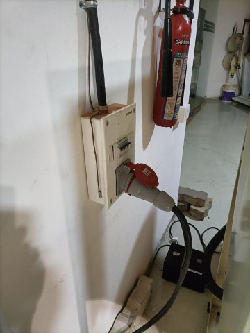
Ensure safety before you start.
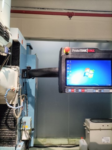
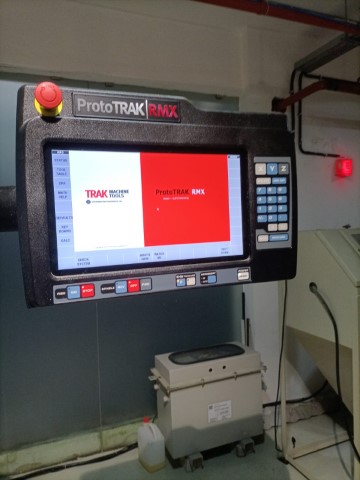
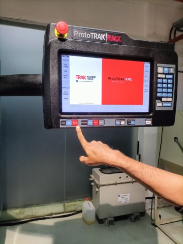
Turn on the power to the TRAK DPM RX2 milling machine.
Allow the machine to initialize. Follow any on-screen prompts or initialization procedures.
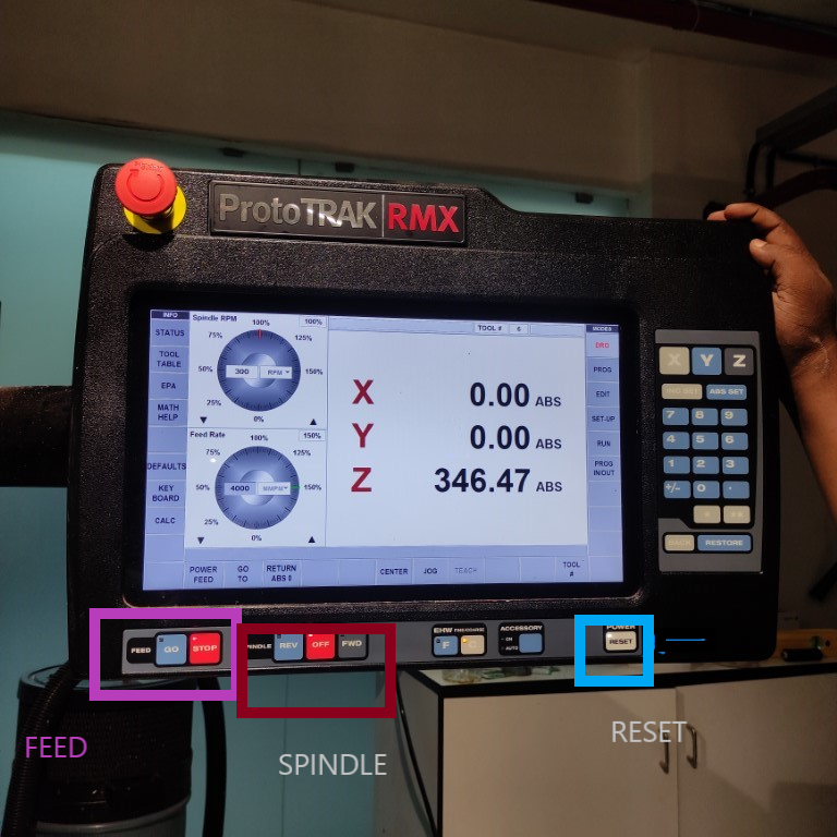
This is the 'Feed' button and the 'Spindle'. Always if you have to stop the machine, first press the Stop near
the 'Feed' button. Then press the 'Off' near the 'Spindle' button.
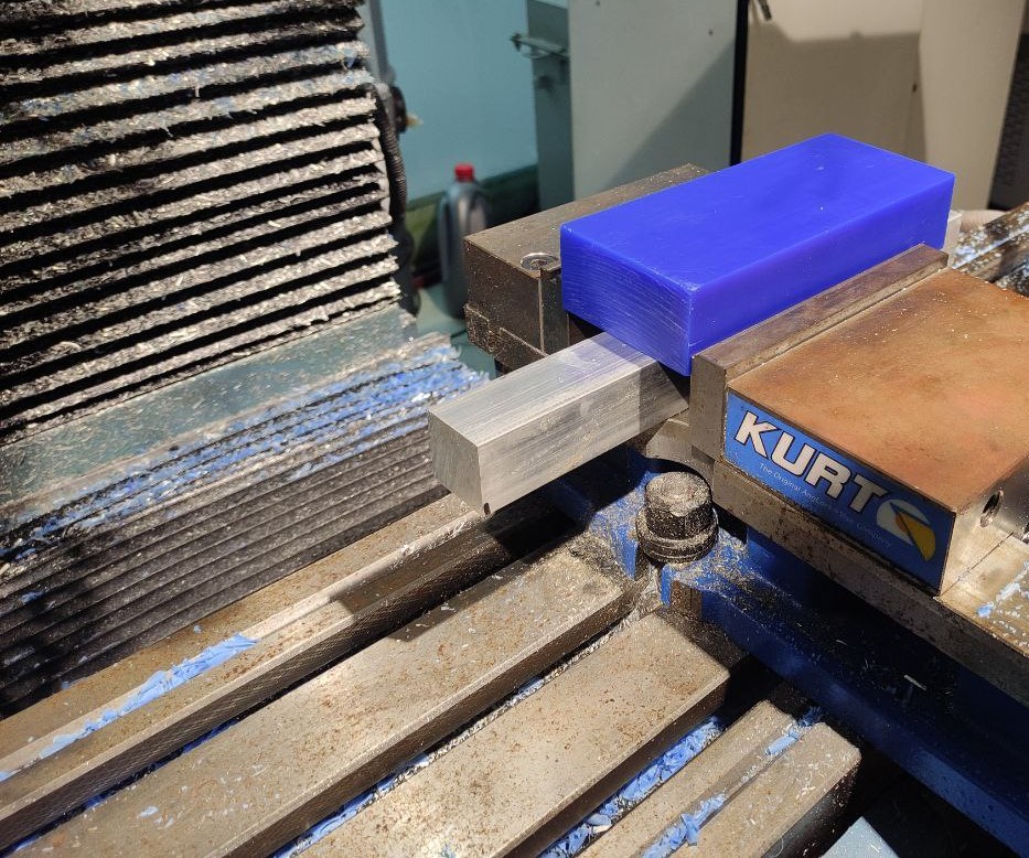
Clamp the wax block securely onto the vise, as shown.
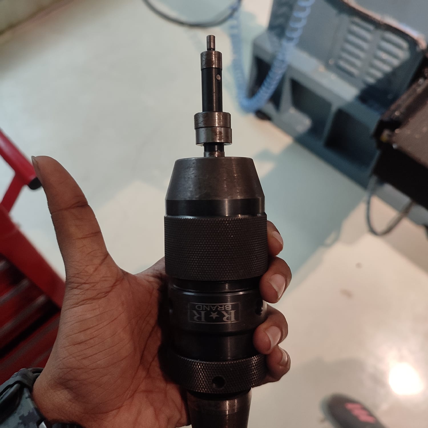
To establish the X and Y origin point at the corner of the wax block ,insert the shank of
the edge finder into the chuck of the milling machine spindle.
Ensure that the edge finder is securely held in place to prevent any movement during operation.
Access the Digital Readout (DRO) and activate JOG mode.
Move the milling machine spindle close to the edge of the workpiece where you want to find the coordinate.
Turn on the milling machine spindle at a low speed.
Gently lower the edge finder onto the workpiece surface. The edge finder will wobble slightly as it makes contact
with the edge.
As the edge finder makes contact with the workpiece edge and is aligned with the edge, it will momentarily stop
wobbling and then kick off to one side.
Once the edge finder kicks off, carefully note the position of the milling machine's digital readout (DRO) on
the selected axis.
Zero the DRO at this position. This establishes the coordinate of the edge relative to the machine zero point.
Calculate the actual coordinate of the edge based on the diameter of the edge finder and its offset from the
spindle centerline.
Repeat the same steps for 'y' coordinate also.
For 'Z' axis, we can choose a reference point on the machine table.
Use the jog controls to move the Z-axis in the desired directionzwhile observing the position of the tool or
spindle in relation to the reference point on the table.
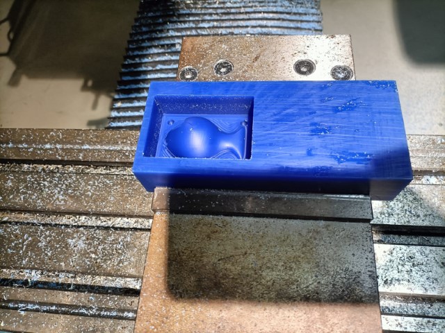
Milling the mold
Load the 6mm flat bit into the machine spindle and tighten it securely.
Set the X and Y origin points at the desired starting position on the workpiece surface, typically at one corner
or center.Begin with the 6mm flat bit for roughing out the mold shape.
Switch to the 3mm flat bit for finer detail work and finishing passes. This smaller bit allows for greater
precision in machining intricate features of the mold.
Use light cuts and slower feed rates to achieve smooth surface finishes without risking tool breakage or
chatter.
Finally, switch to the 3mm round bit to add any necessary fillets, chamfers, or other small details to the mold
surface.
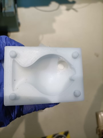
Molding
To make the mold, I had to place the 3d printed eye. It was not fitting perfectly. To attach the part, I heated the
mould with the hot air gun but unfortunately, a
small piece broke off. Saheen helped me fix the part. It was quite difficult since the part that broke off was too
small and though the 3d printed part
had a fillet, the fish mould didn't. I missed putting one.
I needed to know how much resin I'd need, so I had to measure the wax mold's total volume.
I filled the mold with water and marked the level on a glass. This showed me how much space the mold took up.
Next, I weighed the water-filled mold. This told me the weight of both the mold and the water.
Then, I used strong air to clean any leftover water from the mold. It was important to remove all water so it
wouldn't mix with the resin.
With the marked level and the mold's weight, I figured out how much space the wax mold took up. This helped me
figure out how much resin I would need.
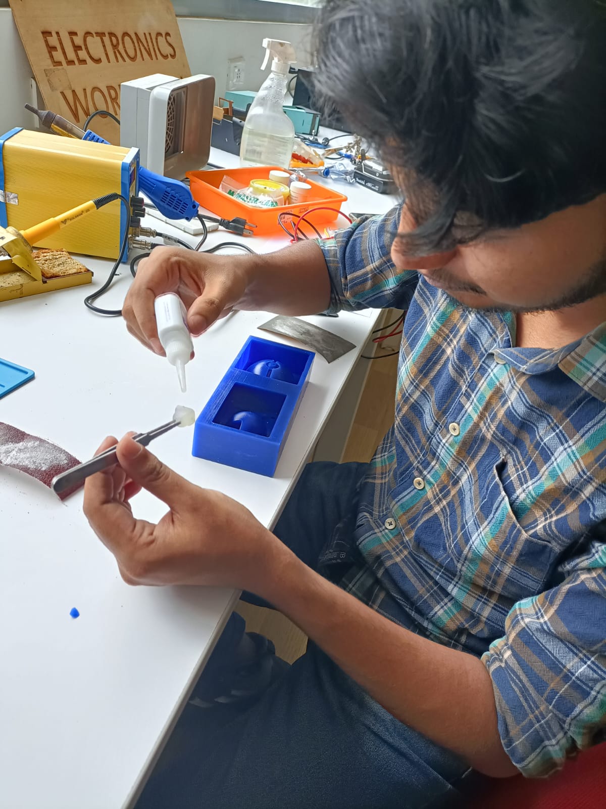
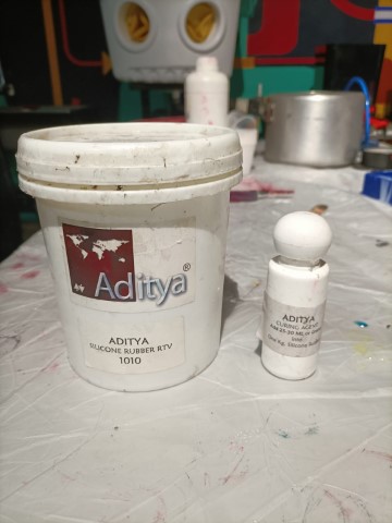
Here, I used Adithy brand Silicon Rubber RTV 1010, and curing agent.
I followed the recommendation and mixed 20 grams of silicone rubber with 1 gram of curing agent. To make sure
there
were no air bubbles, I mixed it slowly and really well. After pouring, I tapped the mould to get rid of air
bubbles.Then, I let it cure for 24 hours, as instructed.
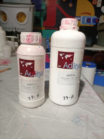
Casting
For casting, I'll be using Adithy brand resin. The composition requires that Part B be half the amount of Part A. Part A was 16gms for me,
so Part B would be 8gms.
I needed to determine the volume of the cast, just like I did with the silicone mold, so I marked it
accordingly.
Then, I weighed it, following the same process I used earlier.
To create the positive mold, I thoroughly mixed part A and part B of the silicone rubber. I made sure to mix
them slowly to prevent air bubbles from forming
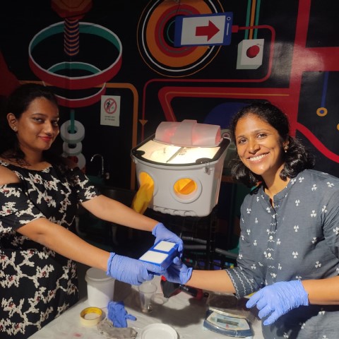
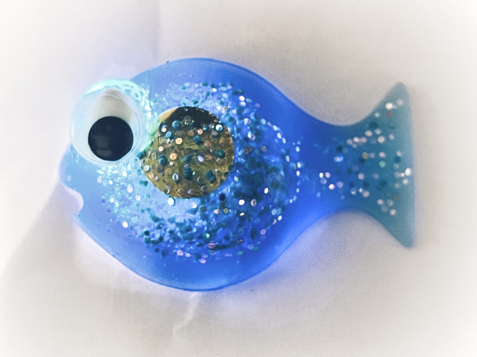
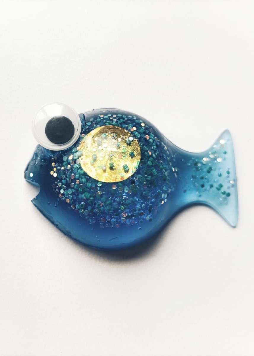
We utilized a custom-built vacuum chamber to remove air from the resin after mixing, ensuring it sets without any bubbles.
I added glitter and I wanted a gold coin (a sequence) in the fish's belly.
.png)
.png)
.png)
.png)
.png)
.png)
.png)
.png)
.png)
.png)
.png)
.png)
.png)
.png)
.jpg)
.jpg)
.jpg)