Input Devices
The assignments for this week:
- Group assignment :
- probe an input device's analog levels and digital signals
- Individual assignment:
- measure something: add a sensor to a microcontroller board that you have designed and read it
ADXL345 Digital Acccelerometer
An accelerometer is a device that detects and measures both stationary (such as gravity) and moving (such as
motion
or vibration) accelerations. It gauges proper acceleration, which is the acceleration relative to freefall and
what
individuals and objects experience. For instance, when an accelerometer is stationary on the Earth's surface, it
registers an acceleration due to gravity, which is directed upwards at approximately 9.81 m/s^2. Conversely, in
free
fall, where an object is descending towards the Earth's center at a rate of about 9.81 m/s^2, the accelerometer
reads zero.
Conceptually, an accelerometer behaves as a damped mass on a spring. When the accelerometer experiences an
acceleration, the mass is displaced to the point that the spring is able to accelerate the mass at the same rate
as the casing. The displacement is then measured to give the acceleration.
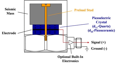
There are many different ways to make an accelerometer.Some accelerometers use the piezoelectric effect-they
contain microscopic crystal structures that get stressed by accelerative forces, which causes a voltage to be
generated.

Another way to do it is by sensing changes in capacitance. If you have two microstructures next to each other,
they have a certain capacitance between them. If an accelerative force moves one of the structures, then the
capacitance will change. When we add a circuitry, it can convert from capacitance to voltage, and it will be an
accelerometer.
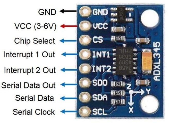
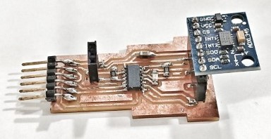
The ADXL345 is a 3-axis accelerometer developed by Analog Devices. This sensor is designed to accurately measure
acceleration in the X, Y, and Z axes, making it suitable for various applications. It is particularly popular in
the
fields of robotics, gaming, virtual reality, wearables, and IoT devices, among others.This accelerometer is
capable of detecting both static acceleration, such as the force of gravity, and dynamic acceleration resulting
from motion or vibrations. The ADXL345 has adjustable sensitivity, enabling it to cater to a range of applications
with different acceleration requirements.
The ADXL345 communicates with microcontrollers using either I2C or SPI interfaces, which makes it compatible with
a wide range of development platforms, such as Arduino, Raspberry Pi Pico, and others.
.jpg)
Specifications of ADXL345
The ADXL345 is a triple-axis accelerometer with the following key specifications:Pinout of ADXL345
ATtiny 1614
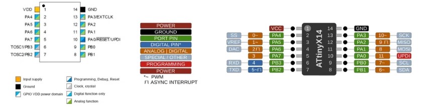
Using the ATtiny1614 microcontroller with the ADXL345 accelerometer is a practical and efficient choice for a variety of reasons:
Interfacing ADXL345 and ATtiny1614
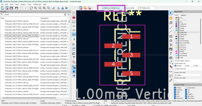
There was no footprint library available for the 1x 08 socket which is to be used for the accelerometer. These are the steps I followed to add a library:
- Launch the KiCad software on your computer.
- Open your PCB layout project in KiCad.
- Navigate to the "Footprint Editor" in KiCad
- Load a footprint template for a 1x05 socket.Select this footprint template since it closely matches the dimensions and pin layout for 1x08 socket.
- In the footprint editor, modify the existing 1x05 socket footprint to accommodate the additional pins of the 1x08 socket. Ensure that the spacing dimensions are set to 2.54mm
- Add extra pin pads and adjust the spacing to match the pin configuration of the 1x08 socket. Ensure that the footprint dimensions align with the physical dimensions of the 1x08 socket to ensure proper alignment during PCB layout.
- Save the modified footprint library with a new name to distinguish it from the original 1x05 socket footprint.
- Choose a descriptive name that indicates it is a 1x08 socket footprint.
- Once you have created and saved the modified footprint library, associate it with the corresponding component symbol in the schematic.
- In the schematic editor, edit the component properties and select the newly created 1x08 socket footprint from the list of available footprints.
- Update the PCB layout in KiCad to reflect the changes made to the footprint library. Reassign the footprint for the ADXL345 component in the PCB layout to use the newly created 1x08 socket footprint.
- Review the PCB layout to ensure that the 1x08 socket footprint is correctly positioned and aligned with other components.
Using the Quentorres board
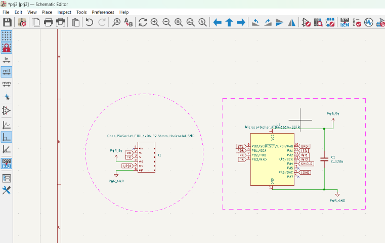
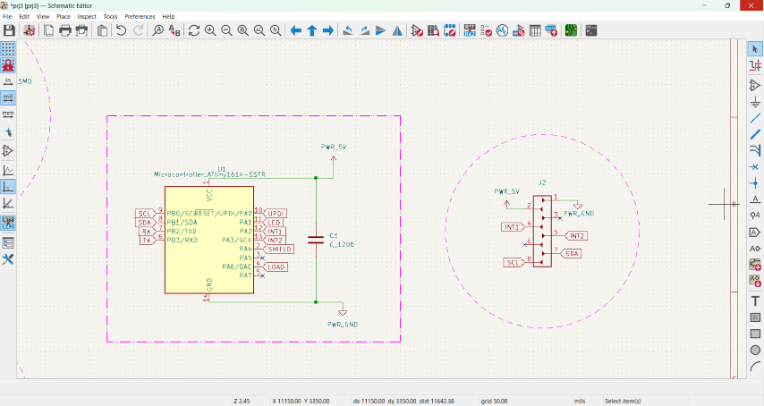
Schematic
.png)
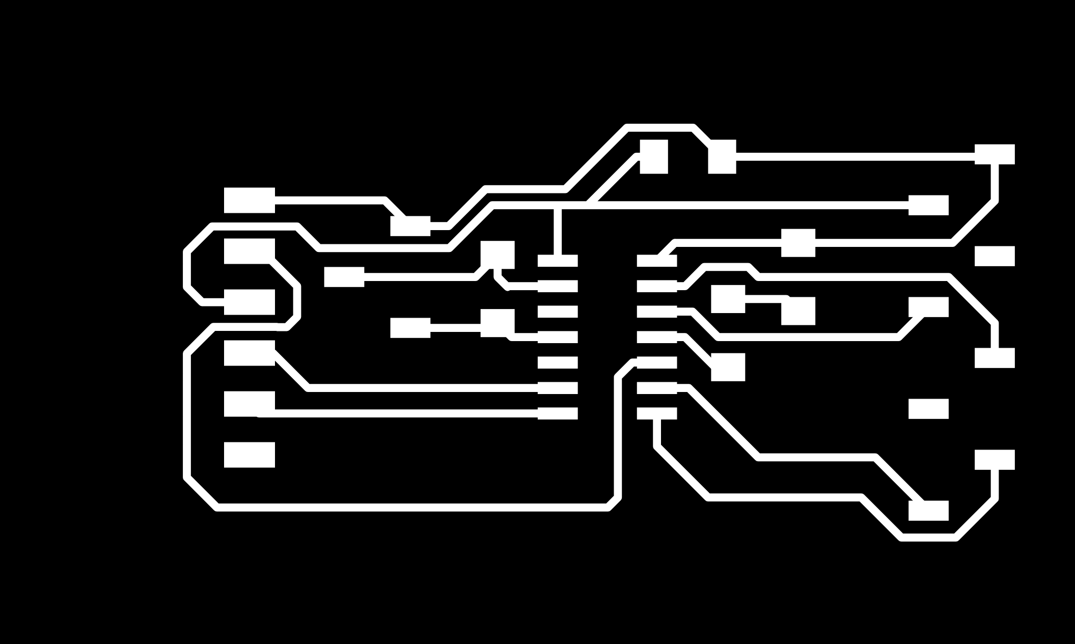
PCB design
Once it is imported to KiCad editor, the components need to be arranged such that the connections don't cross each other.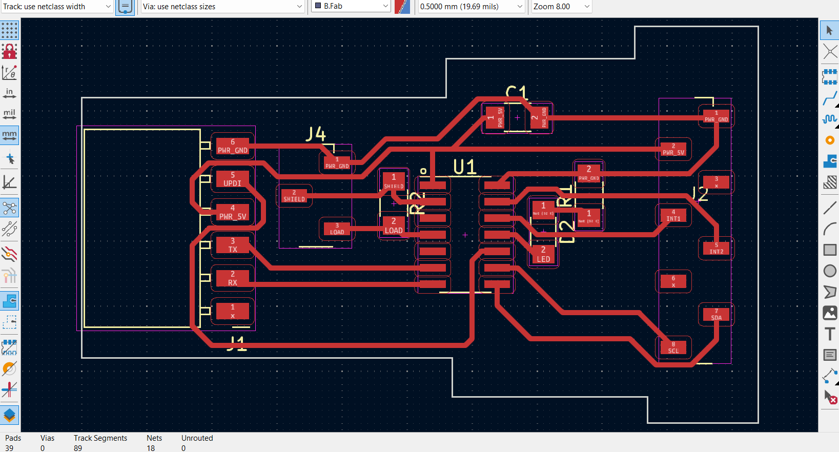
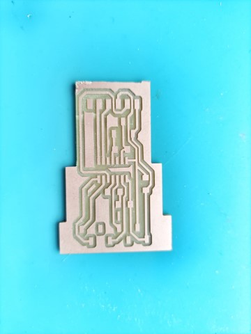
PCB milling
Using the traces mentioned above, I milled the PCB in the Modela using the same procedures mentioned in Week 4 - Electronics Production week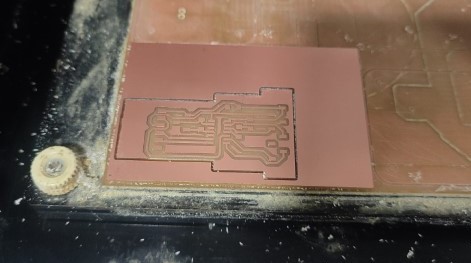
Soldering
I collected the required components from the fablab inventory.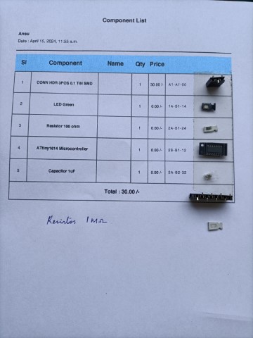
Here again, soldering was done using the same procedures followed in Week 4 - Electronics Production week
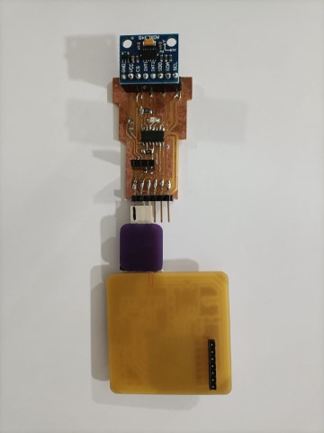
Connecting the boards
The next task involves linking the new board to the Quentorres and subsequently integrating it into the system. Since Quentorres lacks a UPDI pin, we're utilizing an FTDI to UPDI converter available at our FabLab as an intermediary.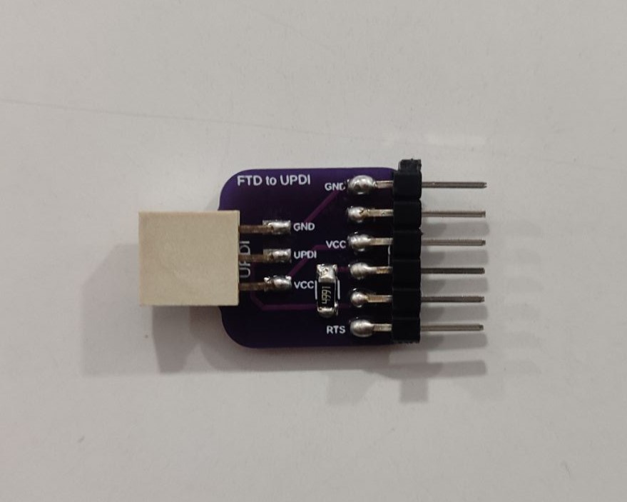
Programming
To blink the LED in the board
    /// ATtiny1614 Blink LED Example

    // Define the pin connected to the LED
    #define LED_PIN 8

    void setup() {
      // Initialize the LED pin as an output
      pinMode(LED_PIN, OUTPUT);
    }

    void loop() {
      // Turn the LED on
      digitalWrite(LED_PIN, HIGH);

      // Wait for 500 milliseconds (0.5 seconds)
      delay(500);

      // Turn the LED off
      digitalWrite(LED_PIN, LOW);

      // Wait for another 500 milliseconds
      delay(500);
    }
This program is from the example for sensortest in Arduino IDE.
      #include  // Include the Wire library for I2C communication
        #include  // Include the Adafruit Sensor library
        #include  // Include the Adafruit ADXL345 library

        // Assign a unique ID to this sensor
        Adafruit_ADXL345_Unified accel = Adafruit_ADXL345_Unified(12345);

        // Function to display sensor details
        void displaySensorDetails(void) {
          sensor_t sensor;
          accel.getSensor(&sensor);
          Serial.println("------------------------------------");
          Serial.print("Sensor:       "); Serial.println(sensor.name);
          Serial.print("Driver Ver:   "); Serial.println(sensor.version);
          Serial.print("Unique ID:    "); Serial.println(sensor.sensor_id);
          Serial.print("Max Value:    "); Serial.print(sensor.max_value); Serial.println(" m/s^2");
          Serial.print("Min Value:    "); Serial.print(sensor.min_value); Serial.println(" m/s^2");
          Serial.print("Resolution:   "); Serial.print(sensor.resolution); Serial.println(" m/s^2");
          Serial.println("------------------------------------");
          Serial.println("");
          delay(500);
        }

        // Function to display the data rate of the accelerometer
        void displayDataRate(void) {
          Serial.print("Data Rate:    ");

          // Print the current data rate
          switch(accel.getDataRate()) {
            case ADXL345_DATARATE_3200_HZ:
              Serial.print("3200 ");
              break;
            case ADXL345_DATARATE_1600_HZ:
              Serial.print("1600 ");
              break;
            case ADXL345_DATARATE_800_HZ:
              Serial.print("800 ");
              break;
            case ADXL345_DATARATE_400_HZ:
              Serial.print("400 ");
              break;
            case ADXL345_DATARATE_200_HZ:
              Serial.print("200 ");
              break;
            case ADXL345_DATARATE_100_HZ:
              Serial.print("100 ");
              break;
            case ADXL345_DATARATE_50_HZ:
              Serial.print("50 ");
              break;
            case ADXL345_DATARATE_25_HZ:
              Serial.print("25 ");
              break;
            case ADXL345_DATARATE_12_5_HZ:
              Serial.print("12.5 ");
              break;
            case ADXL345_DATARATE_6_25HZ:
              Serial.print("6.25 ");
              break;
            case ADXL345_DATARATE_3_13_HZ:
              Serial.print("3.13 ");
              break;
            case ADXL345_DATARATE_1_56_HZ:
              Serial.print("1.56 ");
              break;
            case ADXL345_DATARATE_0_78_HZ:
              Serial.print("0.78 ");
              break;
            case ADXL345_DATARATE_0_39_HZ:
              Serial.print("0.39 ");
              break;
            case ADXL345_DATARATE_0_20_HZ:
              Serial.print("0.20 ");
              break;
            case ADXL345_DATARATE_0_10_HZ:
              Serial.print("0.10 ");
              break;
            default:
              Serial.print("???? ");
              break;
          }
          Serial.println(" Hz");
        }

        // Function to display the range of the accelerometer
        void displayRange(void) {
          Serial.print("Range:         +/- ");

          // Print the current range
          switch(accel.getRange()) {
            case ADXL345_RANGE_16_G:
              Serial.print("16 ");
              break;
            case ADXL345_RANGE_8_G:
              Serial.print("8 ");
              break;
            case ADXL345_RANGE_4_G:
              Serial.print("4 ");
              break;
            case ADXL345_RANGE_2_G:
              Serial.print("2 ");
              break;
            default:
              Serial.print("?? ");
              break;
          }
          Serial.println(" g");
        }

        // Setup function runs once when the microcontroller starts
        void setup(void) {
          #ifndef ESP8266
            while (!Serial); // Wait for serial port to connect (for Leonardo/Micro/Zero)
          #endif
          Serial.begin(9600); // Initialize serial communication at 9600 baud rate
          Serial.println("Accelerometer Test"); Serial.println("");

          // Initialize the sensor
          if(!accel.begin()) {
            // If there's a problem detecting the ADXL345, check the connections
            Serial.println("Ooops, no ADXL345 detected ... Check your wiring!");
            while(1);
          }

          // Set the range to whatever is appropriate for your project
          accel.setRange(ADXL345_RANGE_16_G);
          // accel.setRange(ADXL345_RANGE_8_G);
          // accel.setRange(ADXL345_RANGE_4_G);
          // accel.setRange(ADXL345_RANGE_2_G);

          // Display some basic information on this sensor
          displaySensorDetails();

          // Display additional settings (outside the scope of sensor_t)
          displayDataRate();
          displayRange();
          Serial.println("");
        }

        // Loop function runs continuously after setup
        void loop(void) {
          // Get a new sensor event
          sensors_event_t event;
          accel.getEvent(&event);

          // Display the results (acceleration is measured in m/s^2)
          Serial.print("X: "); Serial.print(event.acceleration.x); Serial.print("  ");
          Serial.print("Y: "); Serial.print(event.acceleration.y); Serial.print("  ");
          Serial.print("Z: "); Serial.print(event.acceleration.z); Serial.print("  ");Serial.println("m/s^2 ");
          delay(500); // Wait for 500 milliseconds before the next loop iteration
        }
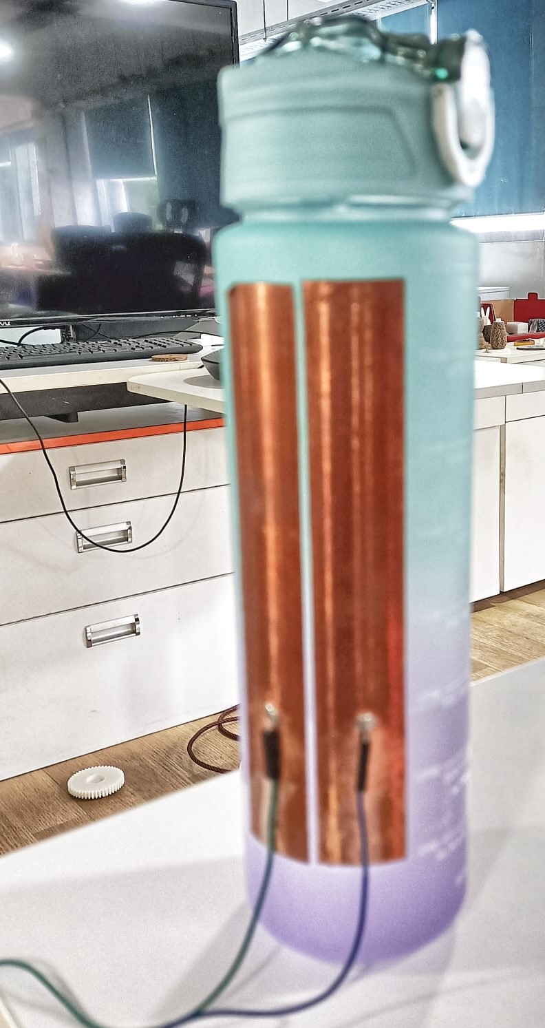
Testing the accelerometer on a bottle
The 'z' values change indicating that the bottle has been lifted up to drink water.Testing step response
From Neil's input class Water has a high dielectric constant (about 80), compared to air (about 1). This means the presence of water between the plates significantly increases the capacitance.
      //
// hello.txrx.t1624.ino
//
// ATtiny1624 step response
//
// Neil Gershenfeld 11/14/21
//
// This work may be reproduced, modified, distributed,
// performed, and displayed for any purpose, but must
// acknowledge this project. Copyright is retained and
// must be preserved. The work is provided as is; no
// warranty is provided, and users accept all liability.
//

#define rxpin PIN_PA4 // receive pin
#define txpin PIN_PA5 // transmit pin
#define settle 100 // settle time
#define samples 100 // number of samples to accumulate

void setup() {
   Serial.begin(115200); // start serial
   pinMode(txpin,OUTPUT); // set transmit pin to output
   analogSampleDuration(5); // speed up ADC sampling
   analogReadResolution(12); // increase ADC resolution
   }

void loop() {
   int32_t up,down;
   up = down = 0;
   noInterrupts(); // disable interrupts while measuring
   for (int i = 0; i < samples; ++i) {
      digitalWriteFast(txpin,HIGH); // charge up
      up += analogRead(rxpin); // read
      delayMicroseconds(settle); //settle
      digitalWriteFast(txpin,LOW); // charge down
      down += analogRead(rxpin); // read
      delayMicroseconds(settle); // settle
      }
   interrupts(); // enable interrupts after measuring
   Serial.println(up-down); // send difference
   Serial.flush(); // finish communicating before measuring
   }
However, this is for an ATtiny1624 and I had a board with ATtiny1614 done in the Input week where I had given a pinout for doing this test with a 1Mohm resistor between the pins. Chatgpt modified the code for ATtiny1614 as below:
      //
// hello.txrx.t1614.ino
//
// ATtiny1614 step response
//
// Adapted by ChatGPT 05/23/24
//
// This work may be reproduced, modified, distributed,
// performed, and displayed for any purpose, but must
// acknowledge this project. Copyright is retained and
// must be preserved. The work is provided as is; no
// warranty is provided, and users accept all liability.
//

#define rxpin PIN_PA4 // receive pin (PA4 on ATtiny1614)
#define txpin PIN_PA5 // transmit pin (PA5 on ATtiny1614)
#define settle 100 // settle time
#define samples 100 // number of samples to accumulate

void setup() {
   Serial.begin(115200); // start serial
   pinMode(txpin, OUTPUT); // set transmit pin to output
   analogReadResolution(12); // increase ADC resolution
   }

void loop() {
   int32_t up, down;
   up = down = 0;
   noInterrupts(); // disable interrupts while measuring
   for (int i = 0; i < samples; ++i) {
      digitalWrite(txpin, HIGH); // charge up
      up += analogRead(rxpin); // read
      delayMicroseconds(settle); // settle
      digitalWrite(txpin, LOW); // charge down
      down += analogRead(rxpin); // read
      delayMicroseconds(settle); // settle
      }
   interrupts(); // enable interrupts after measuring
   Serial.println(up - down); // send difference
   Serial.flush(); // finish communicating before measuring
   }
From Chatgpt:
Explanation of Changes:
Pin Definitions: The pin definitions for rxpin and txpin are set to PIN_PA4 and PIN_PA5 respectively, as they are suitable for the ATtiny1614.
analogSampleDuration: The analogSampleDuration function is not directly supported in standard Arduino for ATtiny1614. Instead, ensuring proper ADC resolution is sufficient.
digitalWriteFast: Changed to digitalWrite since digitalWriteFast is not a standard function in all environments. You may need to use digitalWriteFast if you have the appropriate library; otherwise, digitalWrite should be adequate. Make sure you have the correct core and libraries for the ATtiny1614 when programming your board. You may need to use the MegaTinyCore for this purpose.
This is the error I got in Arduino:
In function 'check_valid_resolution', inlined from 'analogReadResolution.constprop' at C:\Users\DELL\AppData\Local\Arduino15\packages\megaTinyCore\hardware\megaavr\2.3.1\cores\megatinycore\wiring_analog.c:137:3, inlined from 'setup' at C:\Users\DELL\AppData\Local\Temp\.arduinoIDE-unsaved2024423-23584-1kq8zdi.11id\sketch_may23a\sketch_may23a.ino:23:24, inlined from 'main' at C:\Users\DELL\AppData\Local\Arduino15\packages\megaTinyCore\hardware\megaavr\2.3.1\cores\megatinycore\main.cpp:51:8: C:\Users\DELL\AppData\Local\Arduino15\packages\megaTinyCore\hardware\megaavr\2.3.1\cores\megatinycore\wiring_analog.c:124:7: error: call to 'badArg' declared with attribute error: badArg("analogReadResolution called with invalid argument - valid options are 8 or 10."); ^ lto-wrapper.exe: fatal error: C:\Users\DELL\AppData\Local\Arduino15\packages\DxCore\tools\avr-gcc\7.3.0-atmel3.6.1-azduino4b/bin/avr-gcc returned 1 exit status compilation terminated. c:/users/dell/appdata/local/arduino15/packages/dxcore/tools/avr-gcc/7.3.0-atmel3.6.1-azduino4b/bin/../lib/gcc/avr/7.3.0/../../../../avr/bin/ld.exe: error: lto-wrapper failed collect2.exe: error: ld returned 1 exit status exit status 1 Compilation error: exit status 1
And finally, the corrected code:
  //
// hello.txrx.t1614.ino
//
// ATtiny1614 step response
//
// Adapted by ChatGPT 05/23/24
//
// This work may be reproduced, modified, distributed,
// performed, and displayed for any purpose, but must
// acknowledge this project. Copyright is retained and
// must be preserved. The work is provided as is; no
// warranty is provided, and users accept all liability.
//

#define rxpin PIN_PA4 // receive pin (PA4 on ATtiny1614)
#define txpin PIN_PA5 // transmit pin (PA5 on ATtiny1614)
#define settle 100 // settle time
#define samples 100 // number of samples to accumulate

void setup() {
   Serial.begin(115200); // start serial
   pinMode(txpin, OUTPUT); // set transmit pin to output
   // Ensure ADC is configured correctly
   analogReadResolution(10); // set ADC resolution to 10 bits
   }

void loop() {
   int32_t up, down;
   up = down = 0;
   noInterrupts(); // disable interrupts while measuring
   for (int i = 0; i < samples; ++i) {
      digitalWrite(txpin, HIGH); // charge up
      up += analogRead(rxpin); // read
      delayMicroseconds(settle); // settle
      digitalWrite(txpin, LOW); // charge down
      down += analogRead(rxpin); // read
      delayMicroseconds(settle); // settle
      }
   interrupts(); // enable interrupts after measuring
   Serial.println(up - down); // send difference
   Serial.flush(); // finish communicating before measuring
   }
My instructor , Saheen changed the code as below to monitor the change in water level.
#define rxpin PIN_PA4 // receive pin (PA4 on ATtiny1614)
#define txpin PIN_PA6 // transmit pin (PA5 on ATtiny1614)
#define settle 100 // settle time
#define samples 100 // number of samples to accumulate
int32_t waterLevel =0;
void setup() {
   Serial.begin(115200); // start serial
   pinMode(txpin, OUTPUT); // set transmit pin to output
   // Ensure ADC is configured correctly
   analogReadResolution(10); // set ADC resolution to 10 bits
   }

void loop() {
   int32_t up, down;
   up = down = 0;
   noInterrupts(); // disable interrupts while measuring
   for (int i = 0; i < samples; ++i) {
      digitalWrite(txpin, HIGH); // charge up
      up += analogRead(rxpin); // read
      delayMicroseconds(settle); // settle
      digitalWrite(txpin, LOW); // charge down
      down += analogRead(rxpin); // read
      delayMicroseconds(settle); // settle
      }
   interrupts(); // enable interrupts after measuring
  //  Serial.println(up - down); // send difference
   int32_t diffrence = up-down;
   Serial.print(diffrence);
   waterLevel = map(diffrence,40500,72000,0,100);
   Serial.print("\t");
   Serial.print(waterLevel);
   Serial.println("%");
   Serial.flush(); // finish communicating before measuring
   }
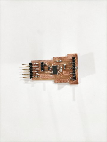
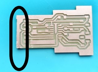
Problems faced
A problem I faced was that I had initially planned on using a socket pin, and space was provided on the board for this purpose. However, only header pins were available in the lab, so I had to modify the board by sawing it to fit the header pins instead.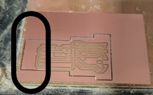
Hero shots
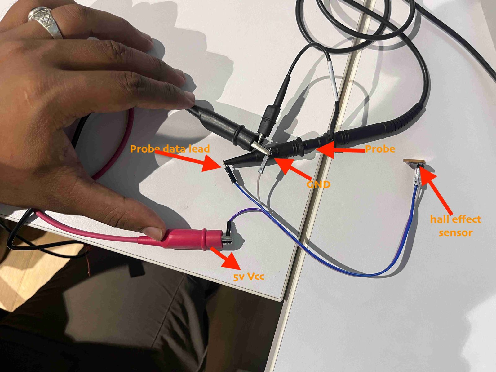
Group assignment:
Input devices' analog levels and digital signals
Design Files
kiCad filesPng file
Png file2