
Embedded Programming
The assignments for this week:
- Group assignment :
- browse through the data sheet for your microcontroller to interact (with local input &/or output devices)
- compare the performance and development workflows for other architectures
- Individual assignment:
- write a program for a microcontroller development board that you made, to interact (with local input &/or output devices) and communicate (with remote wired or wireless devices)
- extra credit: use different languages &/or development environments
- extra credit: connect external components to the board
What is Embedded Programmimg?
Embedded programming refers to the process of writing software specifically designed to run on embedded systems,
which are specialized computer systems built into larger devices or machinery to perform dedicated functions.
These systems typically have limited resources, such as processing power, memory, and input/output capabilities,
and are often designed to operate in real-time or under specific constraints.
Embedded programming involves writing code in low-level languages like C or assembly language to interface
directly with hardware components and control the behavior of the embedded system. It's commonly used in a wide
range of applications,
including consumer electronics, automotive systems, medical devices, industrial automation, and IoT (Internet of
Things) devices.
About Quentorres Board
In week 4, the Quentorres board was introduced to us.The Quentorres,developed at the 2024 Instructors Bootcamp held in León is a board that can program the new AVR Series 1 and 2. It also has a button and an LED to learn to program in C, Rust, Go, Micropython etc. It has breakout pins to connect other external elements. It was created by Quentin Bolsée and redesigned by Adrián Torres.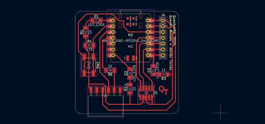
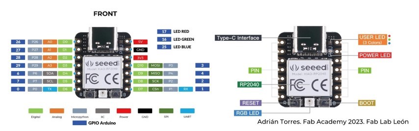
About Seeed Arduino Xiao 2040
The Seeed Arduino XIAO 2040 is a compact development board based on the RP2040 microcontroller chip developed by Raspberry Pi. It is designed for embedded electronics projects and features a small form factor, making it suitable for applications where space is limited. The Seeeduino XIAO 2040 board includes various built-in peripherals, such as GPIO pins, analog inputs, PWM outputs, UART, SPI, I2C interfaces, and USB connectivity. It supports a wide range of development environments, including the Arduino IDE and CircuitPython, making it accessible to both beginners and experienced developers for prototyping and building projects involving sensors, actuators, displays, and more.
Programming the microcontroller development board
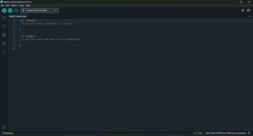
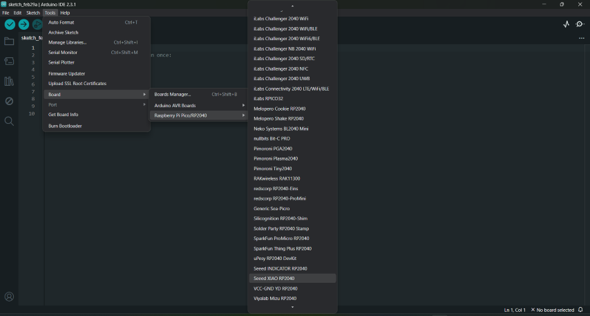
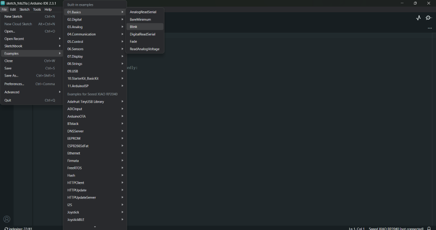
- Open the Arduino IDE 2.3.1 which was installed the earlier week.
- Choose the board from the tools.
- Choose the port
- You can open Examples from here.
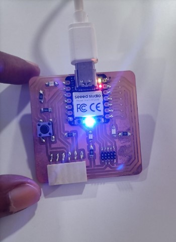
Programming the microcontroller development board to blink
In week 4, We used this example to check whether the builtin LED is blinking.
      void setup() {
      // initialize digital pin LED_BUILTIN as an output.
      pinMode(LED_BUILTIN, OUTPUT);
      }

      // the loop function runs over and over again forever
      void loop() {

      digitalWrite(LED_BUILTIN, HIGH); // turn the LED on (HIGH is the voltage level)
      delay(1000); // wait for a second
      digitalWrite(LED_BUILTIN, LOW); // turn the LED off by making the voltage LOW
      delay(1000); // wait for a second
      }
Programming the microcontroller development board's button
To get familiar with programming, I was asked by our instructor,Saheen, to check out the examples in the
Arduino.Next, we were asked to
learn how a program is written to turns on and off a LED (in this case,connected to digital pin 0)
when pressing a pushbutton (here,attached to pin 27). Saheen suggested we write the algorithm for this to get
familiar with the logic.
Step 1:-Start
Step 2:- Set pin 0 as output for LED and button pin ,27 as input
Step 3:- If button is pressed, go to step 5.
Step 4:- Set LED as off.Go to step 3.
Step 5:- Set LED as on.
Step 6:- Go to step 3.
      const int buttonPin = 27; // the number of the pushbutton pin
      const int ledPin = 0; // the number of the LED pin

      // variables will change:
      int buttonState = 0; // variable for reading the pushbutton status

      void setup() {
      // initialize the LED pin as an output:
      pinMode(ledPin, OUTPUT);
      // initialize the pushbutton pin as an input:
      pinMode(buttonPin, INPUT);
      }

      void loop() {
      // read the state of the pushbutton value:
      buttonState = digitalRead(buttonPin);

      // check if the pushbutton is pressed. If it is, the buttonState is HIGH:
      if (buttonState == HIGH) {
      // turn LED on:
      digitalWrite(ledPin, HIGH);
      } else {
      // turn LED off:
      digitalWrite(ledPin, LOW);
      }
      }
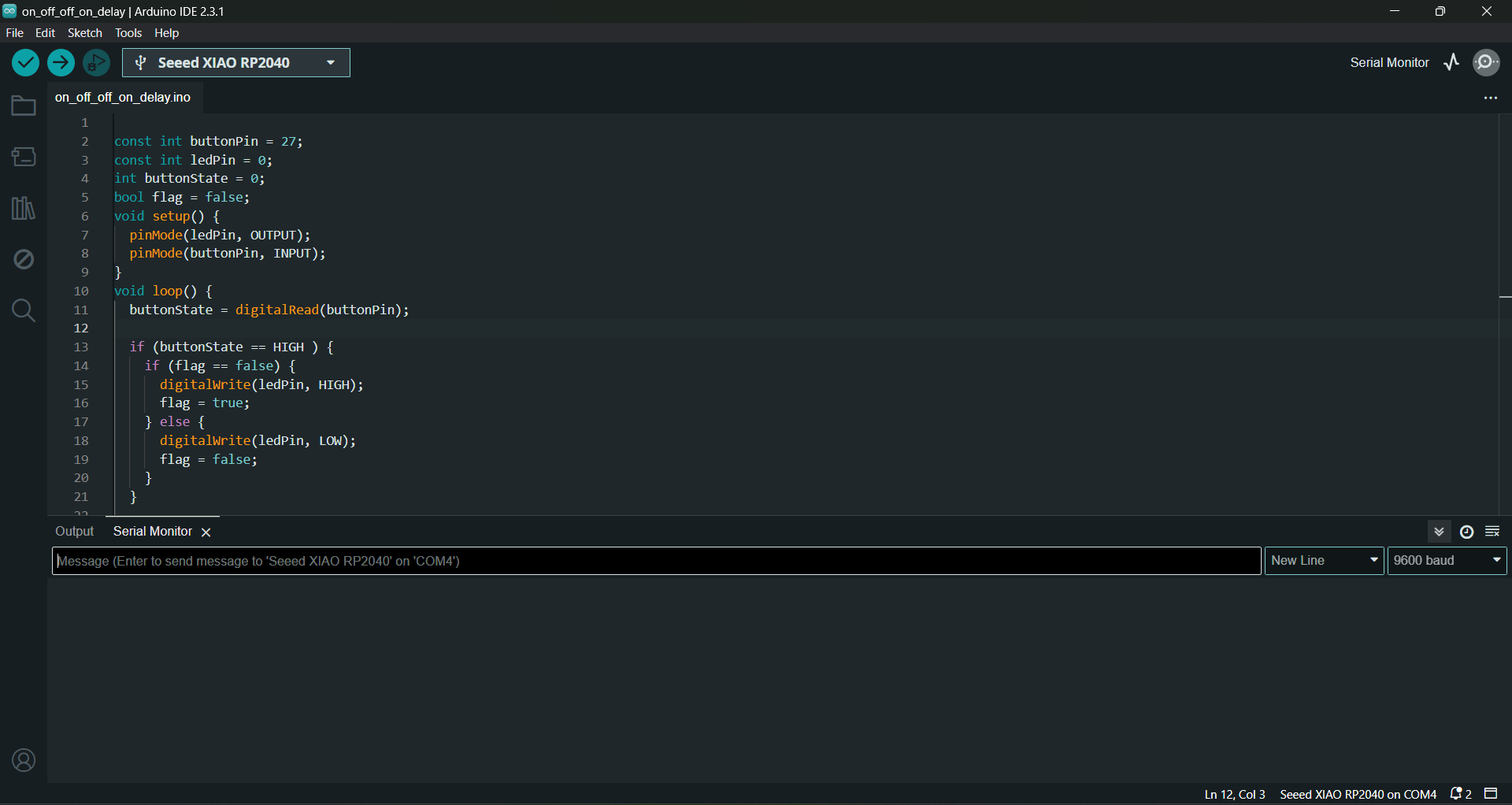
Using Boolean function
Now, to program a boolean function refers to a function that returns a boolean value, which is either true or false. This program is to turn an LED on if it is off or turn it off if it is on using a boolean function , flag. The algorithm fo this:Step 1:-Start
Step 2:- Set buttonPin, 27 as input
Step 3:- Set the LED pin ,13 as output
Step 4:- If indicator is off, go to 5
Step 5:- If button is pressed, switch off LED, go to 7
Step 6:- If button is pressed, switch on LED
Step 7:- Set indicator to on ,Go to step 8
Step 8:- Set indicator to off
Step 9:-Go to step 3
      const int buttonPin = 27; // the number of the pushbutton pin is 27 in the Seed XIAO
      const int ledPin = 0; // the number of the LED pin
      bool flag = false;//this is an indicator which changes to true when button is on
      // variables will change:
      int buttonState = 0; // variable for reading the pushbutton status

      void setup() {
      // initialize the LED pin as an output:
      pinMode(ledPin, OUTPUT);
      // initialize the pushbutton pin as an input:
      pinMode(buttonPin, INPUT);
      }

      void loop() {
      // read the state of the pushbutton value:
      buttonState = digitalRead(buttonPin);

      // check if the pushbutton is pressed. If it is, the buttonState is HIGH:
      if (buttonState == HIGH) {
      flag=!flag;// opposite of bool flag, so if the button is high or on, the flag becomes true
      }
      // turn LED off:
      digitalWrite(ledPin, flag);
      }
Debounce
Debouncing is a technique used to ensure that only one logical transition is registered for each physical transition of an input signal, particularly when dealing with mechanical switches or buttons. When a button is pressed or released, its contacts can momentarily make and break connection rapidly, causing the signal to fluctuate between HIGH and LOW states several times in quick succession. To mitigate this issue, debouncing involves introducing a delay mechanism in the code to ensure that only stable, reliable signals are acted upon. Debouncing can be implemented,here, by adding a short delay (a few milliseconds) after detecting a state change of a button and then rechecking the state of the button to confirm its stable state.
      const int buttonPin = 27; // the number of the pushbutton pin is 27 in the Seed XIAO
      const int ledPin = 0; // the number of the LED pin
      bool flag = false;
      bool pressed=false;
      // variables will change:
      int buttonState = 0; // variable for reading the pushbutton status

      void setup() {
      // initialize the LED pin as an output:
      pinMode(ledPin, OUTPUT);
      // initialize the pushbutton pin as an input:
      pinMode(buttonPin, INPUT);
      delay(2000);//to manage the bounce
      }

      void loop() {
      // read the state of the pushbutton value:
      buttonState = digitalRead(buttonPin);

      // check if the pushbutton is pressed. If it is, the buttonState is HIGH:
      if (buttonState == HIGH) {
      if(pressed==false){
      flag=!flag;// opposite of bool flag, so if the button is high or on, the flag becomes true
      pressed=true;
      }
      }else{
      pressed=false;
      delay(50);
      digitalWrite(ledPin, flag);
      }
      }
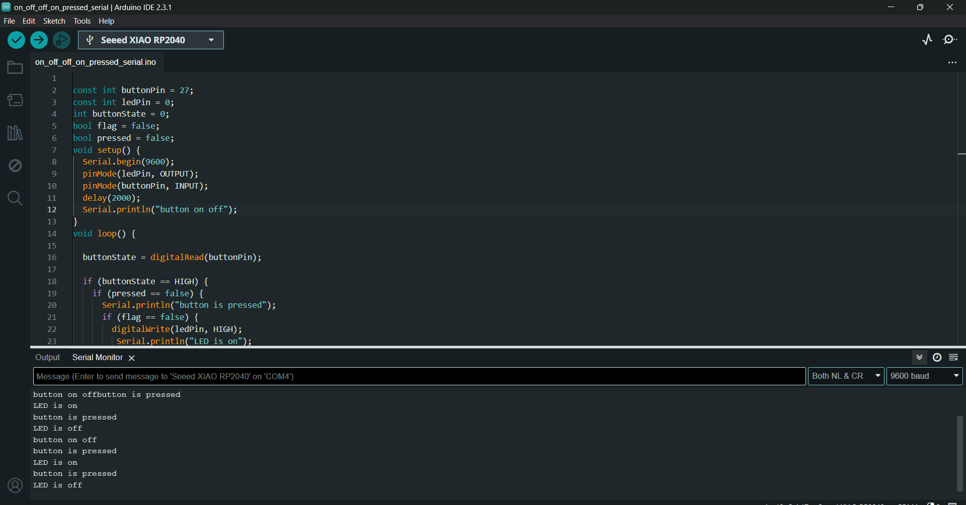
Serial communication
The Serial Monitor in the Arduino IDE is a tool used for communicating with the Arduino board via the serial
port.
It provides a simple interface for sending text data to the Arduino and receiving text data from the Arduino.
Here are some key features and functions of the Serial Monitor:
Viewing Output: The Serial Monitor displays text output from the Arduino board. This output can be generated by
using functions like Serial.print() and Serial.println() in your Arduino sketch.
Sending Input: You can send text input to the Arduino board through the Serial Monitor. This input can be used to
control the behavior of your Arduino sketch or to interact with sensors and actuators connected to the
Arduino.
Baud Rate Configuration: The Serial Monitor allows you to configure the baud rate, which determines the speed of
communication between the Arduino board and your computer. The baud rate must match the baud rate set in your
Arduino sketch using the Serial.begin() function.
Debugging: The Serial Monitor is a valuable tool for debugging Arduino sketches. You can use it to print out
variable values, debug messages, and sensor readings, helping you to troubleshoot and understand the behavior of
your code.
To open the Serial Monitor in the Arduino IDE, you can click on the magnifying glass icon in the toolbar or
navigate to Tools > Serial Monitor. Once opened, you'll be able to interact with your Arduino board in real-time
through the Serial Monitor interface.Here is the modified program with serial communication:
      const int buttonPin = 27;
      const int ledPin = 0;
      int buttonState = 0;
      bool flag = false;
      bool pressed = false;
      void setup() {
      Serial.begin(9600);// 9600 is the baud rate
      pinMode(ledPin, OUTPUT);
      pinMode(buttonPin, INPUT);
      delay(2000);
      Serial.println("button on off");
      }
      void loop() {

      buttonState = digitalRead(buttonPin);

      if (buttonState == HIGH) {
      if (pressed == false) {
      Serial.println("button is pressed");//this is what is to be printed/communicated
      if (flag == false) {
      digitalWrite(ledPin, HIGH);
      Serial.println("LED is on");//this is what is to be printed/communicated
      flag = true;
      } else {
      digitalWrite(ledPin, LOW);
      Serial.println("LED is off");//this is what is to be printed/communicated
      flag = false;
      }
      pressed=true;
      }
      }else{
      pressed = false;
      delay(50);
      }
      }
Calling function
Toggle between the LED when button is pressed using function
Using Chatgpt, I got a program to toggle between the three LEDs sequentially when the button is pressed each time.
      #define BUTTON_PIN 27
      #define LED_1 0
      #define LED_2 1
      #define LED_3 26

      int buttonPressCount = 0; // Global variable to keep track of the number of button presses

      void setup() {
      pinMode(LED_1, OUTPUT);
      pinMode(LED_2, OUTPUT);
      pinMode(LED_3, OUTPUT);
      pinMode(BUTTON_PIN, INPUT_PULLUP);
      Serial.begin(9600);
      delay(2000);
      Serial.println("This is LED button example for FAB ACADEMY 2024");
      }

      void loop() {
      int buttonState = digitalRead(BUTTON_PIN);
      if (buttonState == HIGH) {
      buttonPressCount++; // Increment the button press count
      toggleLED(); // Call the function to toggle the LEDs
      // Wait for the button to be released
      while(digitalRead(BUTTON_PIN) == HIGH);
      delay(50);
      }
      }

      void toggleLED() { //recursive function
      if (buttonPressCount == 1) {
      digitalWrite(LED_1, HIGH);
      digitalWrite(LED_2, LOW);
      digitalWrite(LED_3, LOW);
      Serial.println("LED 1 ON");
      }
      else if (buttonPressCount == 2) {
      digitalWrite(LED_1, LOW);
      digitalWrite(LED_2, HIGH);
      digitalWrite(LED_3, LOW);
      Serial.println("LED 2 ON");
      }
      else if (buttonPressCount == 3) {
      digitalWrite(LED_1, LOW);
      digitalWrite(LED_2, LOW);
      digitalWrite(LED_3, HIGH);
      Serial.println("LED 3 ON");
      }

      if (buttonPressCount >= 3) { // Reset to 1 to start from the first LED again after the third press

      buttonPressCount = 0;
      }
      }
Micro Python
MicroPython enables developers to write Python code to control hardware directly,
making it easier to create projects involving sensors, actuators, and other electronic components.
Thonny, is an Integrated Development Environment (IDE) for Python programming. It provides a user-friendly
interface for writing, editing, running, and debugging Python code.One of the notable features of Thonny is its
built-in support for MicroPython, allowing developers to write and upload MicroPython code to microcontroller
boards directly from the Thonny IDE.
For the software setup and to use MicroPython, I followed these instructions.
It was very clear and in detail.
Seed Studio XIAO RP2040 with MicroPython
.png)
Connect Seeed Studio XIAO RP2040 to the PC and Light it up
      from machine import Pin, Timer

# Initialize the onboard LED pin
led = Pin(25, Pin.OUT)

# Initialize counter and function number variables
Counter = 0
Fun_Num = 0

# Define the callback function for the timer
def fun(tim):
    global Counter
    Counter = Counter + 1
    print(Counter)
    # Toggle the LED state
    led.value(Counter % 2)

# Initialize the timer
tim = Timer(-1)
tim.init(period=1000, mode=Timer.PERIODIC, callback=fun)
.png)
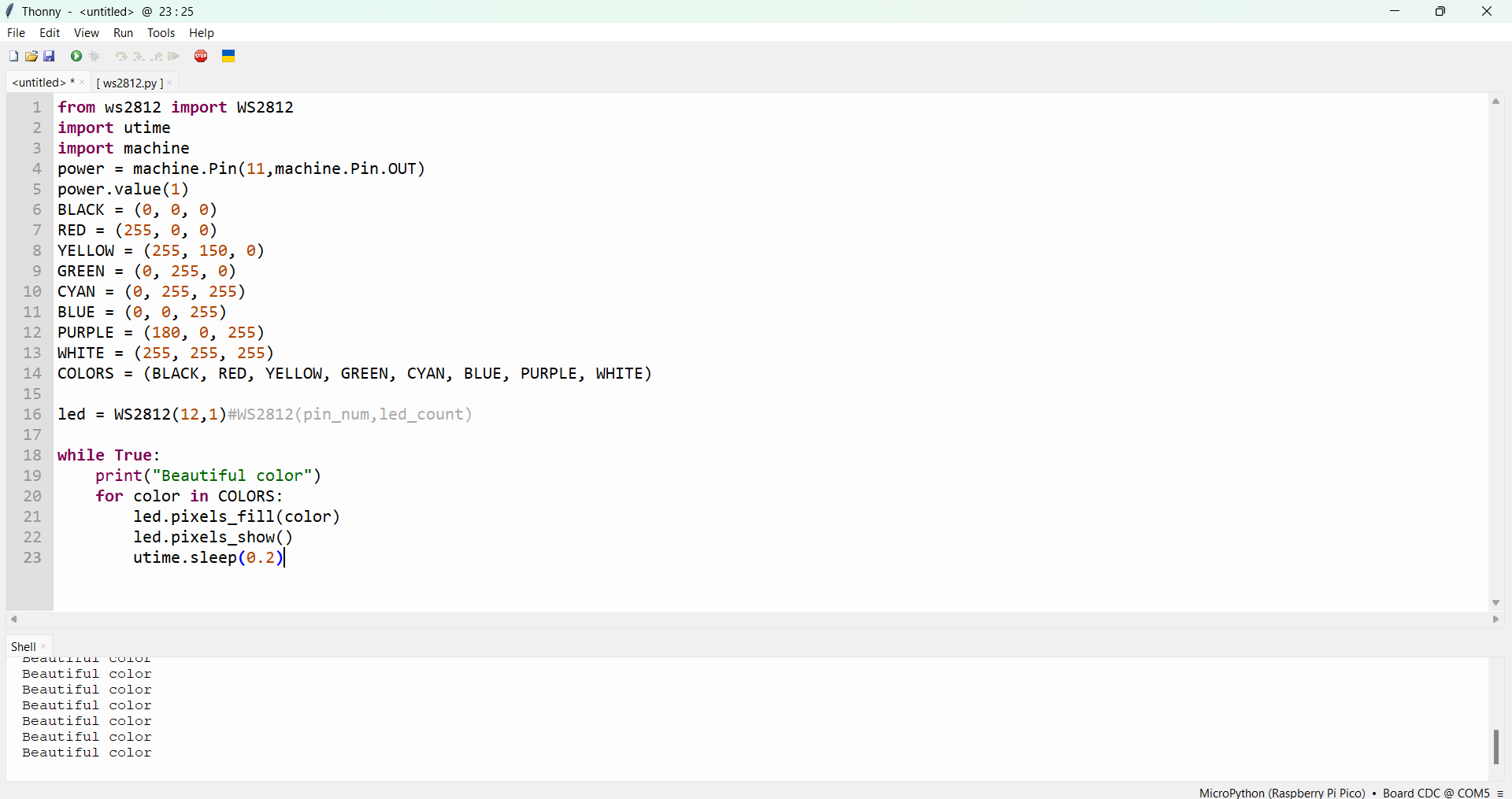
Light up RGB LED on the Seeed Studio XIAO RP2040
      from ws2812 import WS2812
import utime
import machine

# Initialize the power pin for the WS2812 LED strip
power = machine.Pin(11, machine.Pin.OUT)
power.value(1)

# Define colors
BLACK = (0, 0, 0)
RED = (255, 0, 0)
YELLOW = (255, 150, 0)
GREEN = (0, 255, 0)
CYAN = (0, 255, 255)
BLUE = (0, 0, 255)
PURPLE = (180, 0, 255)
WHITE = (255, 255, 255)
COLORS = [BLACK, RED, YELLOW, GREEN, CYAN, BLUE, PURPLE, WHITE]

# Initialize the WS2812 LED strip
led = WS2812(12, 1)  # WS2812(pin_num, led_count)

# Main loop to cycle through the colors
while True:
    print("Beautiful color")
    for color in COLORS:
        led.pixels_fill(color)
        led.pixels_show()
        utime.sleep(0.2)
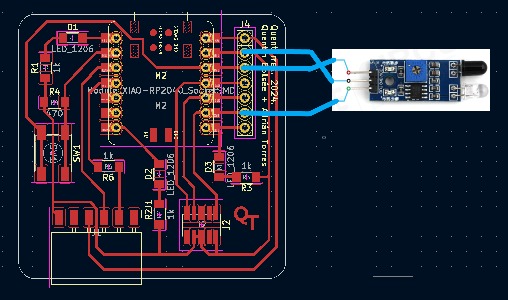
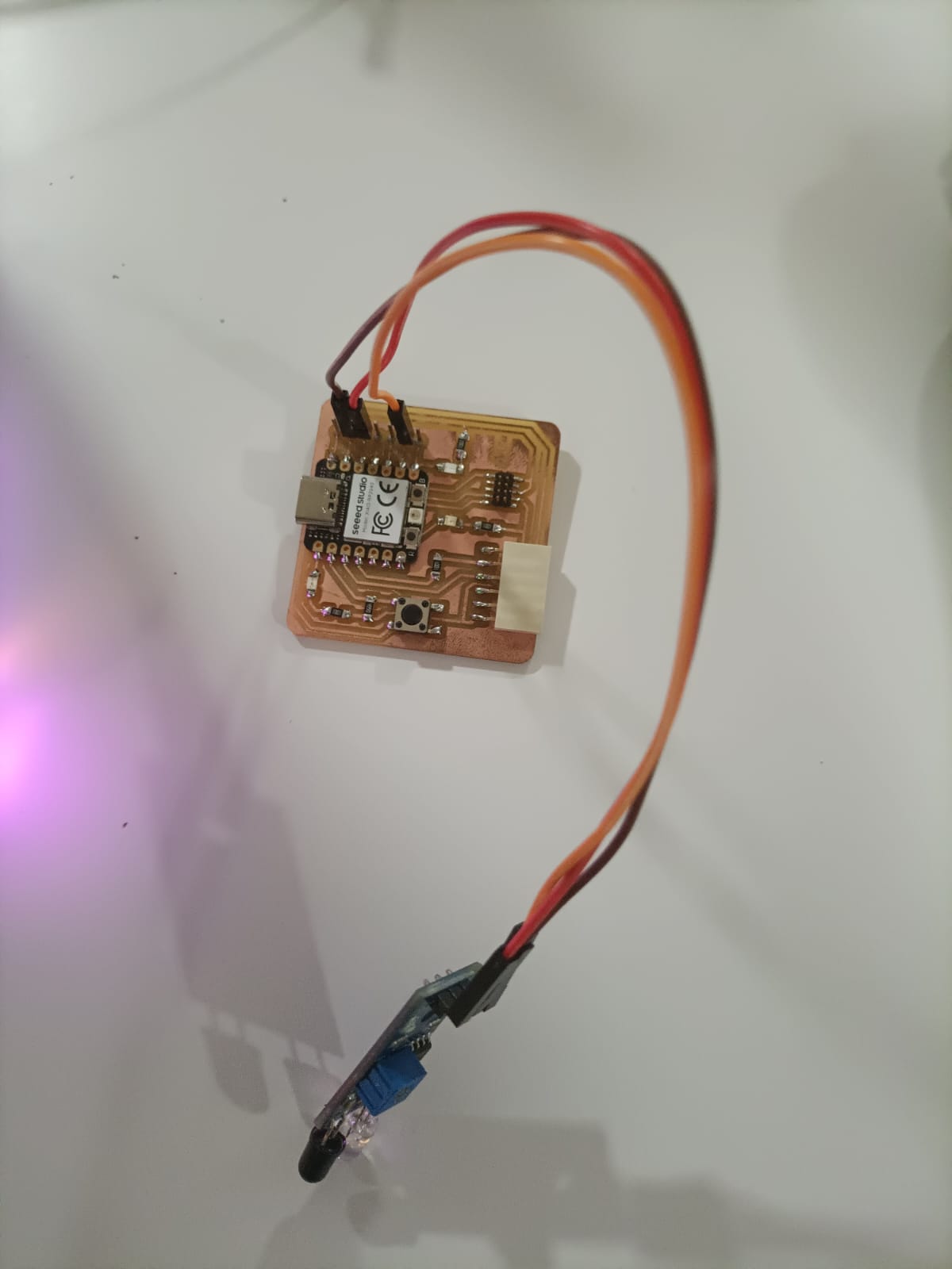
Connecting external components to the board
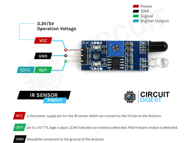
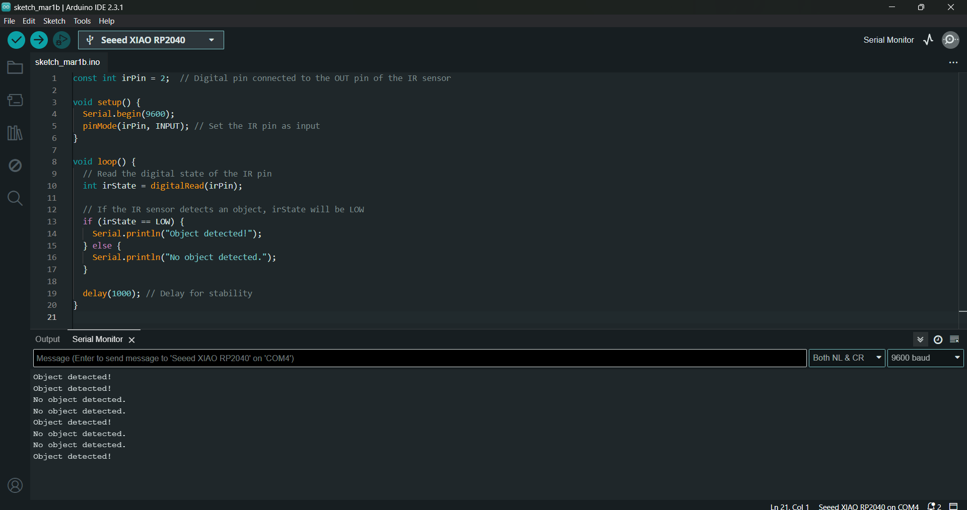
Interfacing IR Sensor Module with Arduino
An infrared proximity sensor or IR Sensor is an electronic device that emits infrared lights to sense some aspect of the surroundings and can be employed to detect the motion of an object. As this is a passive sensor, it can only measure infrared radiation.
      // Define the pin connected to the IR sensor output
      const int irSensorPin = 2;  // Assuming pin 2 is connected to the sensor output

      void setup() {
        // Initialize serial communication for debugging
        Serial.begin(9600);

        // Set IR sensor pin as input
        pinMode(irSensorPin, INPUT);
      }

      void loop() {
        // Read the state of the IR sensor
        int sensorValue = digitalRead(irSensorPin);

        // Check if object is detected
        if (sensorValue == HIGH) {
          Serial.println("Object detected!");
        } else {
          Serial.println("No object detected.");
        }

        // Wait a short delay before reading again
        delay(500);
      }
Interfacing IR Servo motor, MG90S with Arduino
The MG90S servo motor is a compact and reliable motor designed for precise control in robotics and RC projects.
With its metal gear construction and torque of up to 2.2 kg/cm, it offers powerful and accurate movement. This
servo motor features 360-degree rotation, fast response time, and compatibility with various control systems.
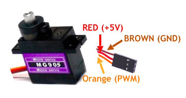
Here is the code to move the servo by 90 degrees.
      #include < Servo.h >
        // Define the servo control pin
        const int servoPin = 1;  // Assuming pin 3 is connected to the servo
                // Create a servo object
        Servo servo;
                void setup() {
          // Attach the servo to the corresponding pin
          servo.attach(servoPin);
                   // Move the servo to the 90-degree position
          servo.write(90);
                    // Wait for a few seconds (adjust as needed)
          delay(3000);
                    // Detach the servo (optional)
          servo.detach();
        }
                void loop() {
          // Nothing here in this example
        }
Communicating using Bluetooth
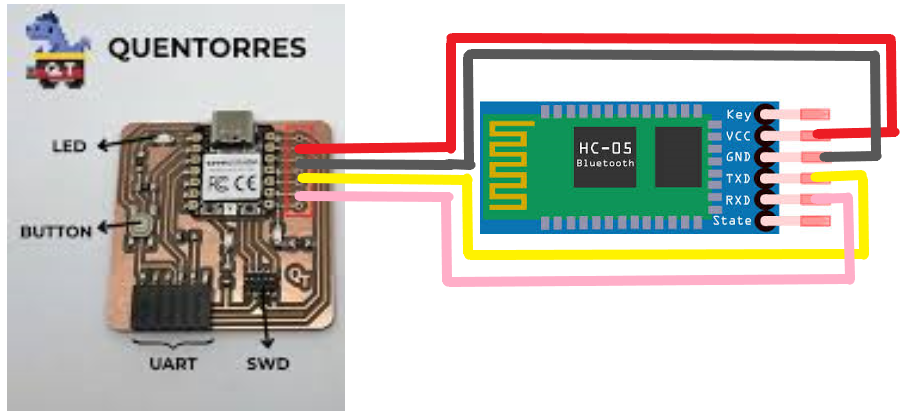
The XIAO RP2040 does not have built-in Bluetooth capability, but you can add Bluetooth functionality using a Bluetooth module or shield, such as the HC-05 or HC-06. These modules allow you to establish a serial communication link wirelessly between the XIAO RP2040 and another Bluetooth-enabled device.
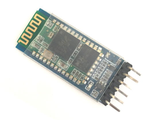
HC-05 is a Bluetooth module which is designed for wireless communication. This module can be used in a master or slave configuration. Bluetooth serial modules allow all serial enabled devices to communicate with each other using Bluetooth. It has 6 pins,
1. Data mode: Exchange of data between devices.
2. Command mode: It uses AT commands which are used to change setting of HC-05. To send these commands to module serial (USART) port is used.
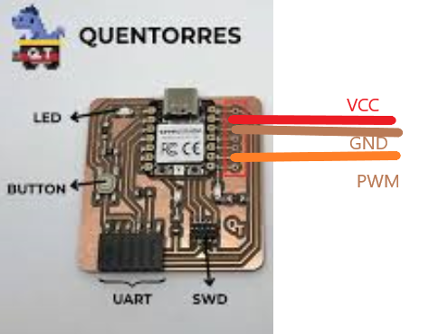
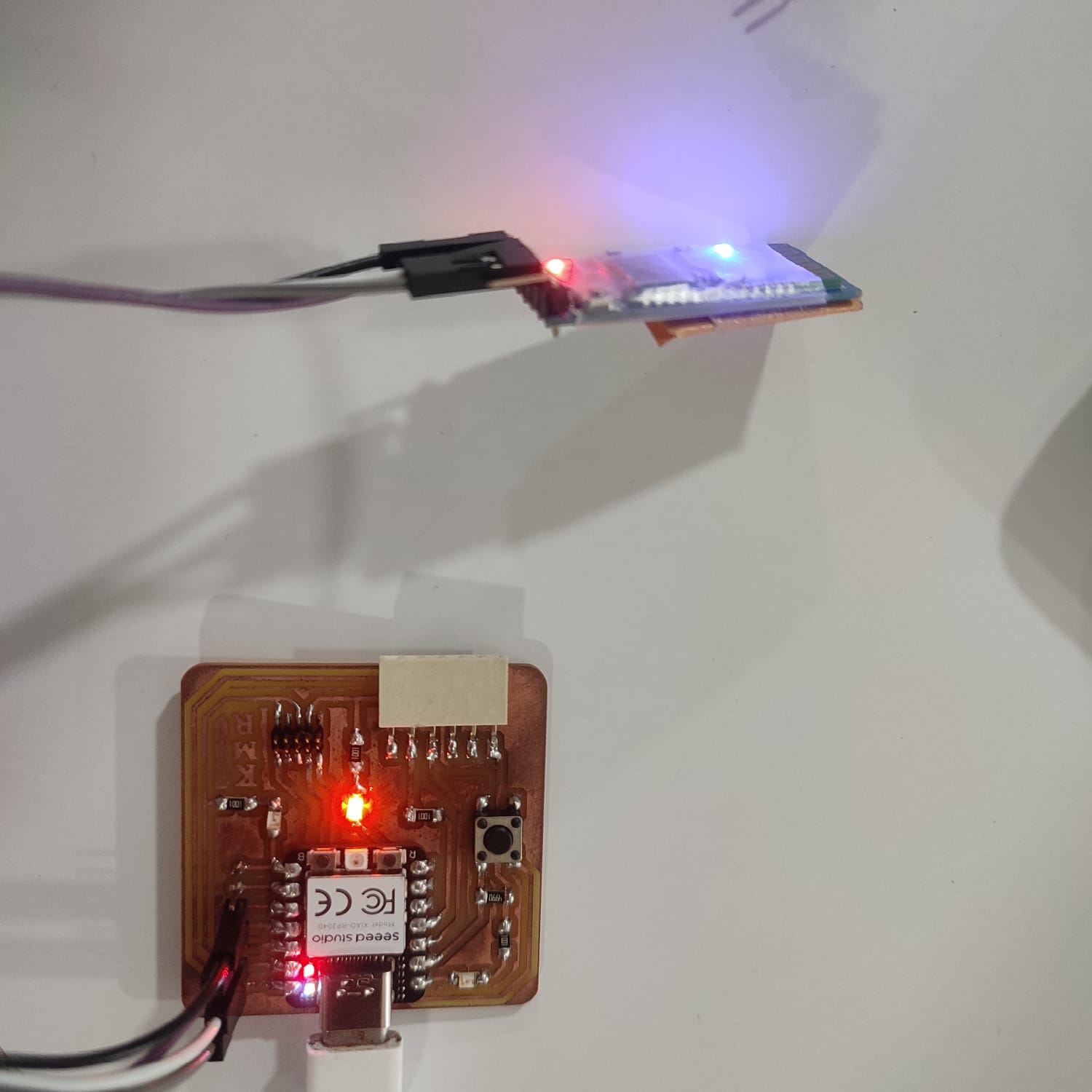
Connecting the Quentorres to the HC-05
      #include < SoftwareSerial.h >

    const int ledPin = 0; // GPIO pin for the LED
    SoftwareSerial bluetoothSerial(3, 4); // RX, TX pins for HC-05

    void setup() {
        Serial.begin(9600);          // Initialize the serial communication for debugging
        bluetoothSerial.begin(9600); // Initialize Bluetooth serial communication
        pinMode(ledPin, OUTPUT);      // Set the LED pin as an output
    }

    void loop() {
        if (bluetoothSerial.available() > 0) {
        char command = bluetoothSerial.read();

        // Toggle LED based on received command
        if (command == '1') {
            digitalWrite(ledPin, HIGH); // Turn on LED
            Serial.println("LED ON");
        } else if (command == '0') {
            digitalWrite(ledPin, LOW);  // Turn off LED
            Serial.println("LED OFF");
        }
      }
    }
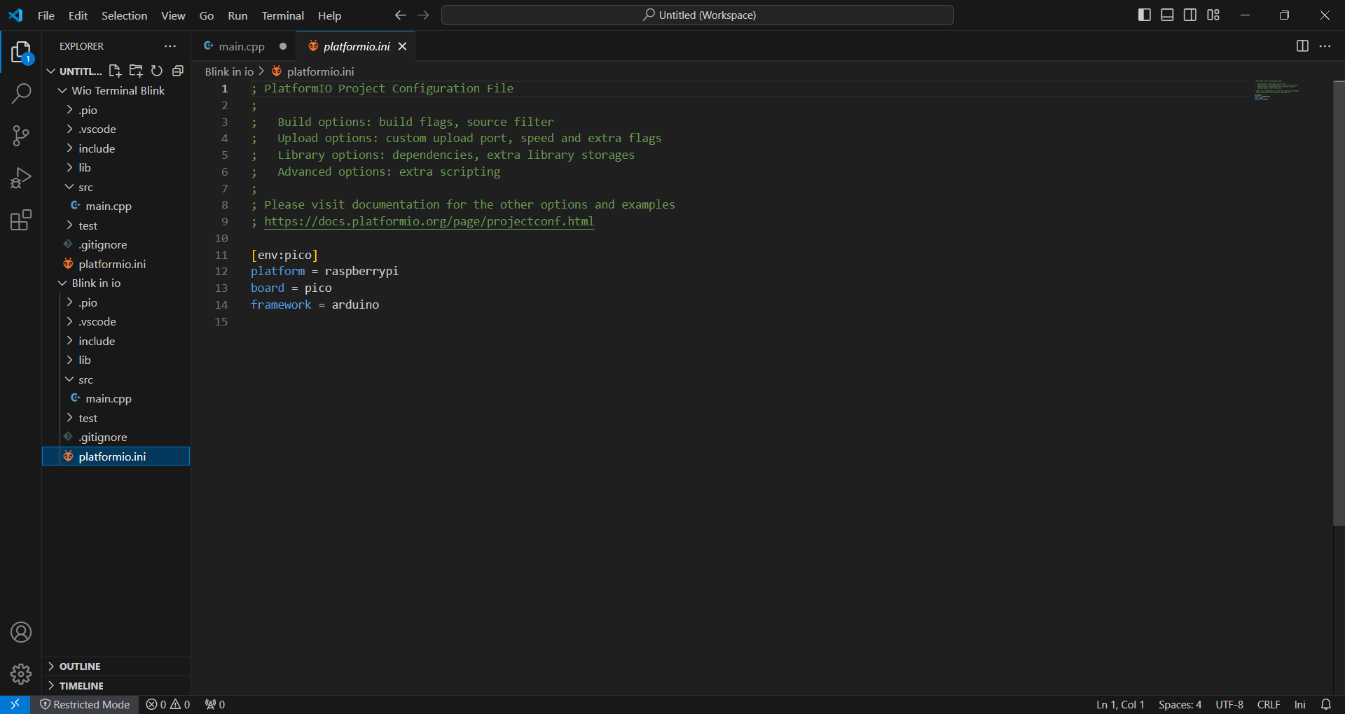
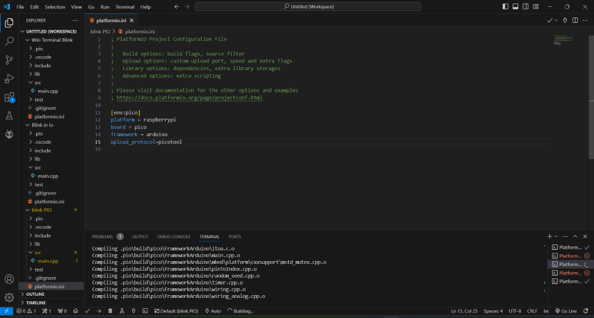
Using PlatformIO IDE for Arduino programming
PlatformIO is a cross-platform, cross-architecture, multi-framework professional IDE tool for embedded system and software engineers to write embedded applications.If you need a simple and easy-to-use environment for a small project, Arduino IDE may be the better choice. If you need a more powerful and feature-rich development environment for a larger project that uses the Arduino framework, PlatformIO IDE may be the better choice.
PlatformIO for VSCode
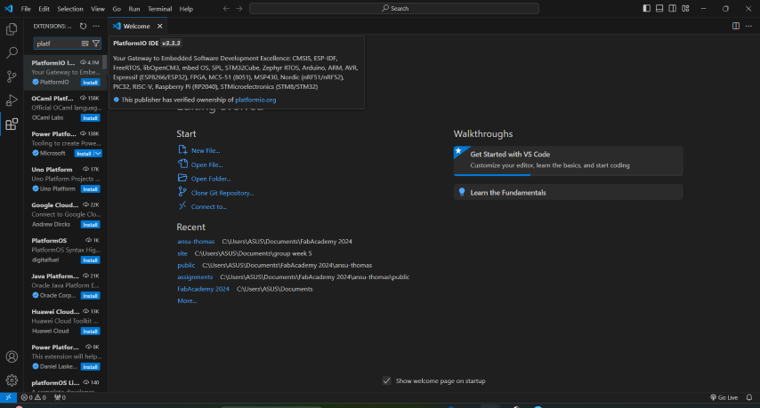
- Download the PlatformIO IDE Plugins for VSCode: Open the Extensions Market in VS Code by clicking the Extensions on the left panel,search PlatfromIO in the Extension Market and click Install
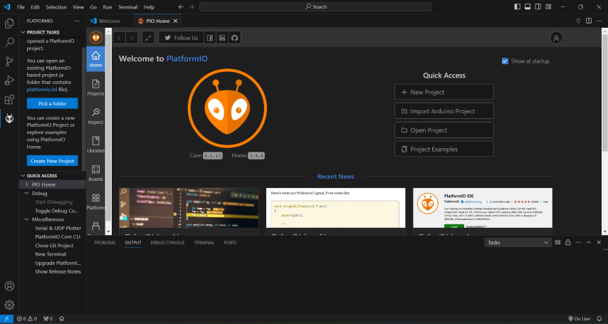
- Opening PlatformIO Home Page: Click on “PlatformIO Home” button on the bottom PlatformIO toolbar. PlatformIO is installed.
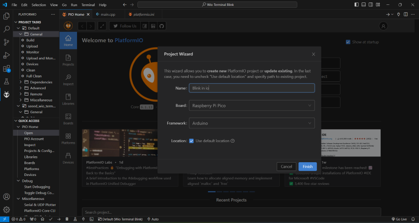
- Click the PlatformIO Home button. Click on New Project and select Raspberry Pi Pico .
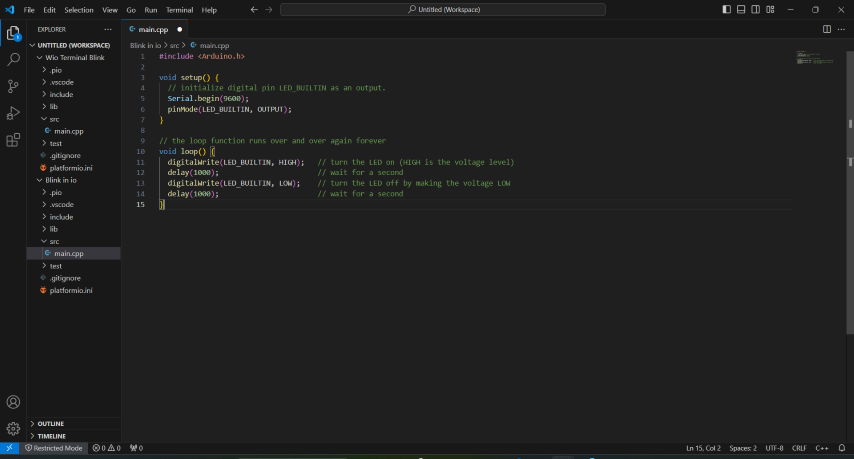
- Open main.cpp under src folder and copy the following:
      #include  < Arduino.h >

        void setup() {
          // initialize digital pin LED_BUILTIN as an output.
          Serial.begin(9600);
          pinMode(LED_BUILTIN, OUTPUT);
        }

        // the loop function runs over and over again forever
        void loop() {
          digitalWrite(LED_BUILTIN, HIGH);   // turn the LED on (HIGH is the voltage level)
          delay(1000);                       // wait for a second
          digitalWrite(LED_BUILTIN, LOW);    // turn the LED off by making the voltage LOW
          delay(1000);                       // wait for a second
        }
Group assignment:
Performance and development workflows