WEEK 9
Output Devices
Group Assignment:
- Measure the power consumption of an output device.
Individual Assignment:
- Add an output device to a microcontroller board you've designed, and program it to do something.
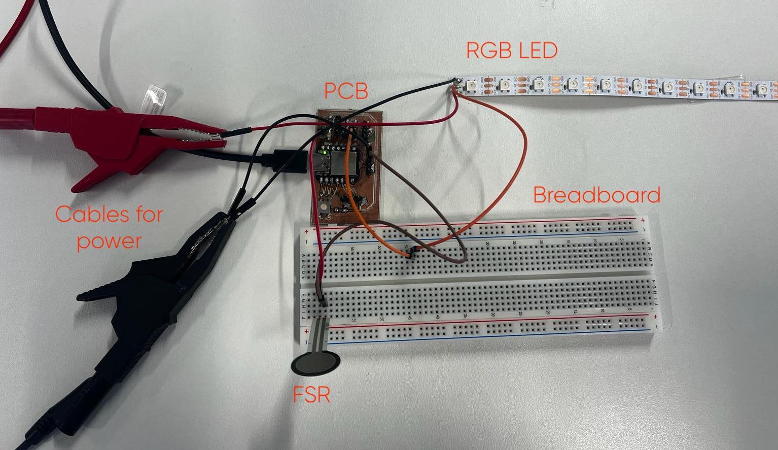
1. Tools and overall look
This week, I aimed to work with RGB LED as an output device. Also, this experiment will help me to develop my final project. During the process, I used the following tools and items.
| Component Name | Purpose of Having |
|---|---|
| 3 Female Cable | Attaching to LED |
| 3 Male to Female Cable | Connecting the PCB to the breadboard. |
| Wire Striper | Peeling to cable skin for soldering. |
| Power Supply | Supplying power to LED. |
| Force Sensitive Sensor | Using like a button. |
| Breadboard | Connecting sensor, PCB and LED to each other. |
| RGB LED | Output device. |
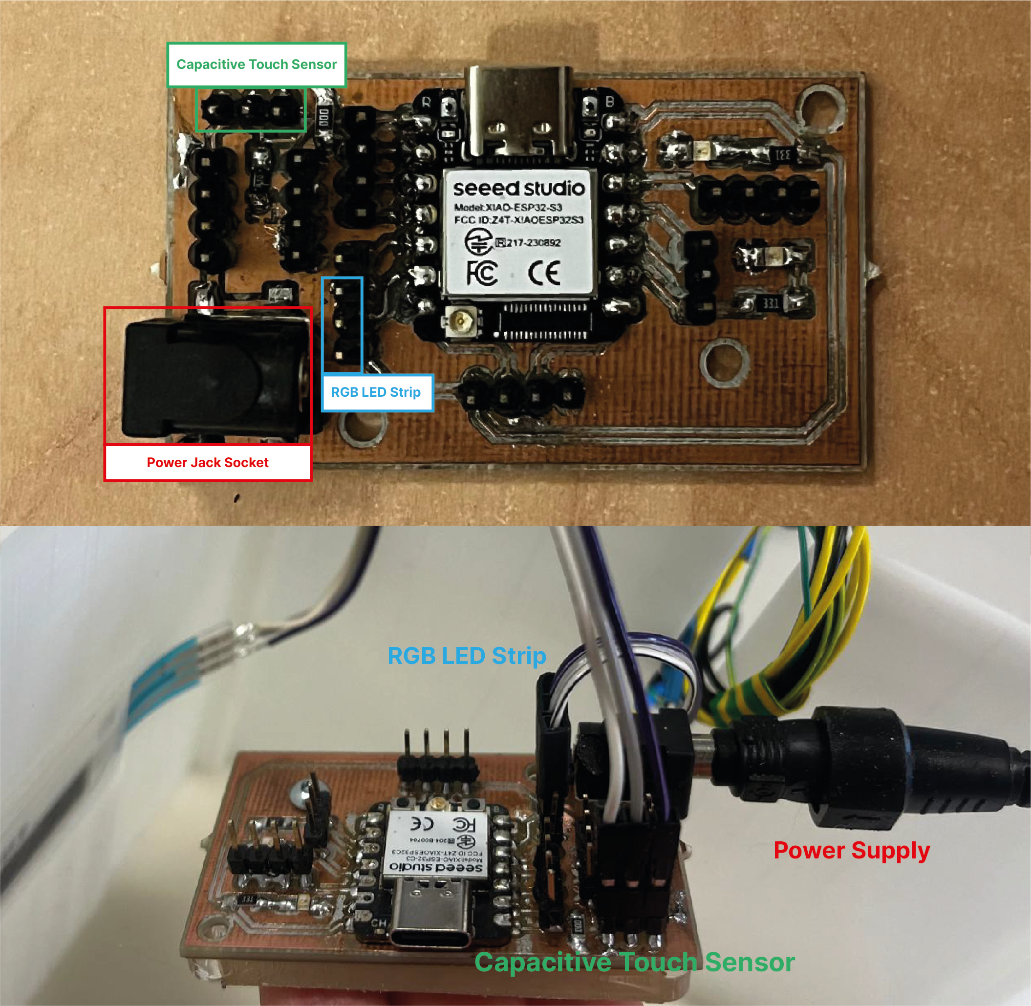
| My pcb design | Controlling the circuit . |
2. Preparing RGB LED
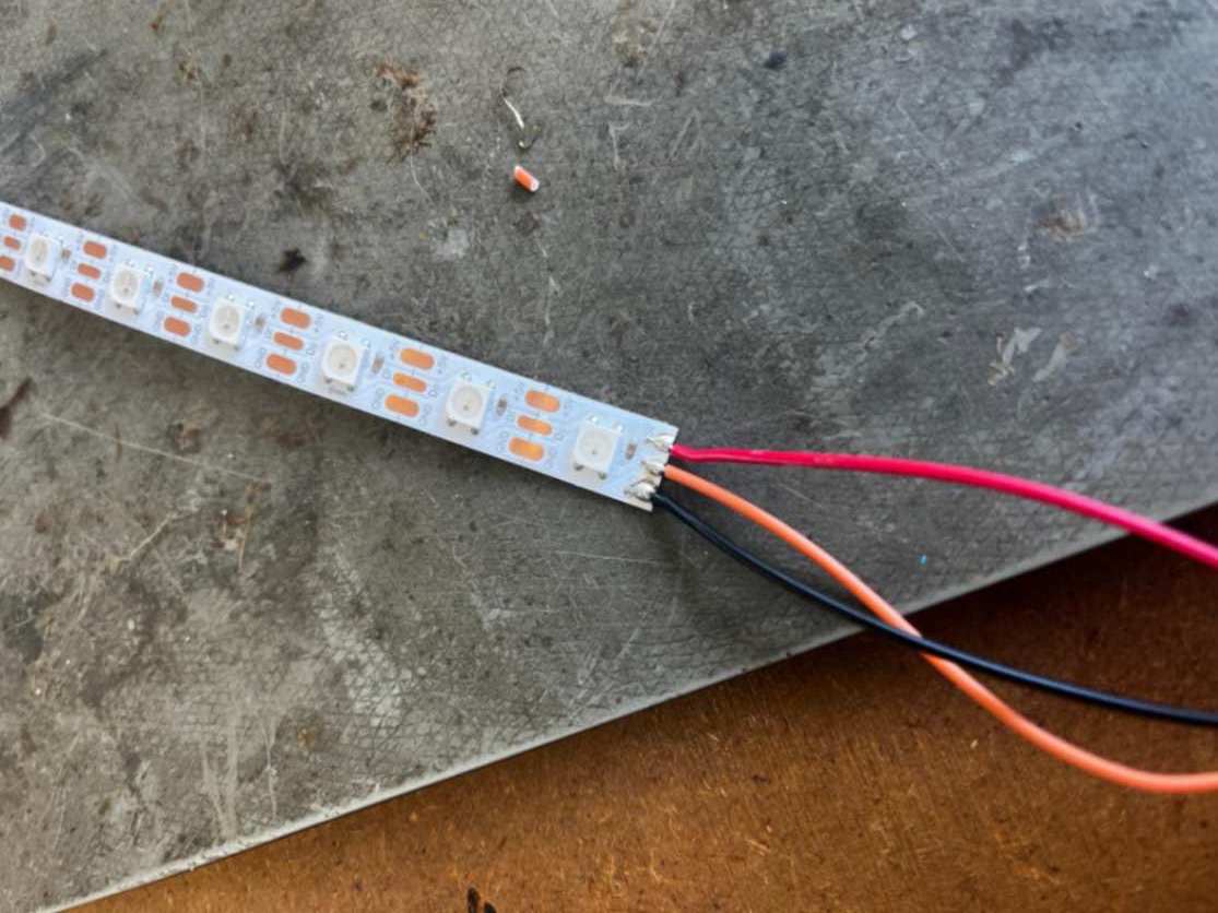
It was my first time working with LED and power suppliers, so my instructor helped me with it. Firstly we cut one side of the 3 female cables and then peeled them with wire stripper. Thus, we could solder them to LED.
- The black cable is used for ground.
- The red cable is for 5V.
- The orange cable is for transferring information such as color and brightness from PCB to LED.
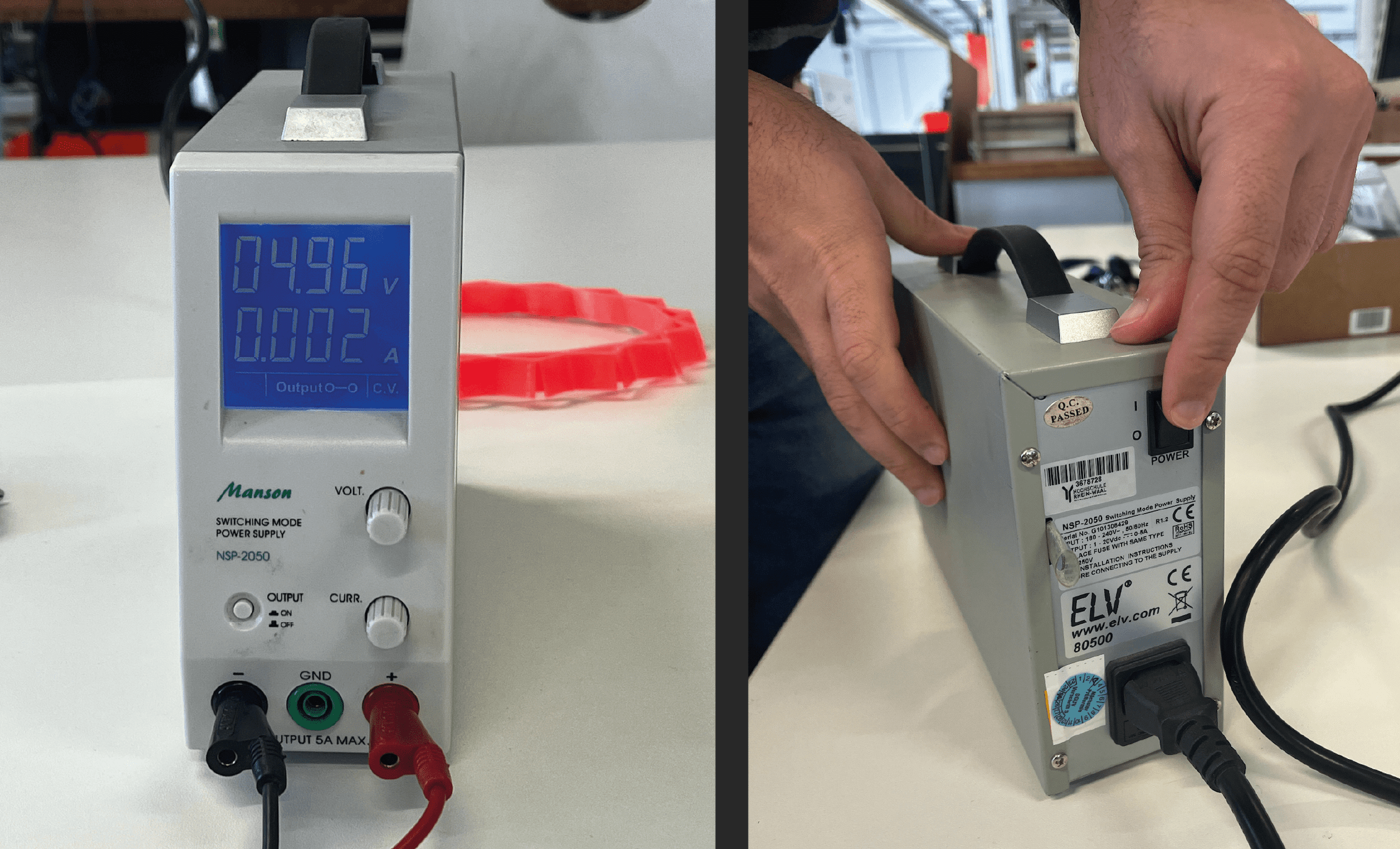
3. Connecting led to Power Supplier
To connect the LED to the power supplier, we used two big different cables. To turn on the power supply, you should plug in the cable and then switch on it. To send electricity through the cables, you should turn on the output. I set the voltage as 5V. Because RGB LEDs output says 5V. On the power supplier;
- Red cable goes to 5V.
- Black goes ground.
4. Connecting led to PCB
To connect the PCB to the LED and power supplier, we attached the orange cable to the breadboard. For the orange cable, it wasn't important which pin of PCB they needed to connect. However, for the red and black cables, we choose the ground and 5V pins.
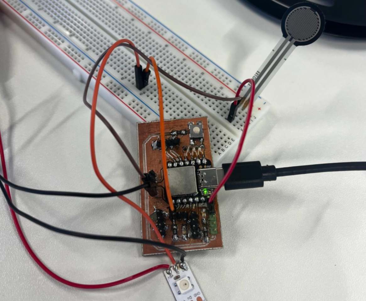
5. Controlling RGB LED
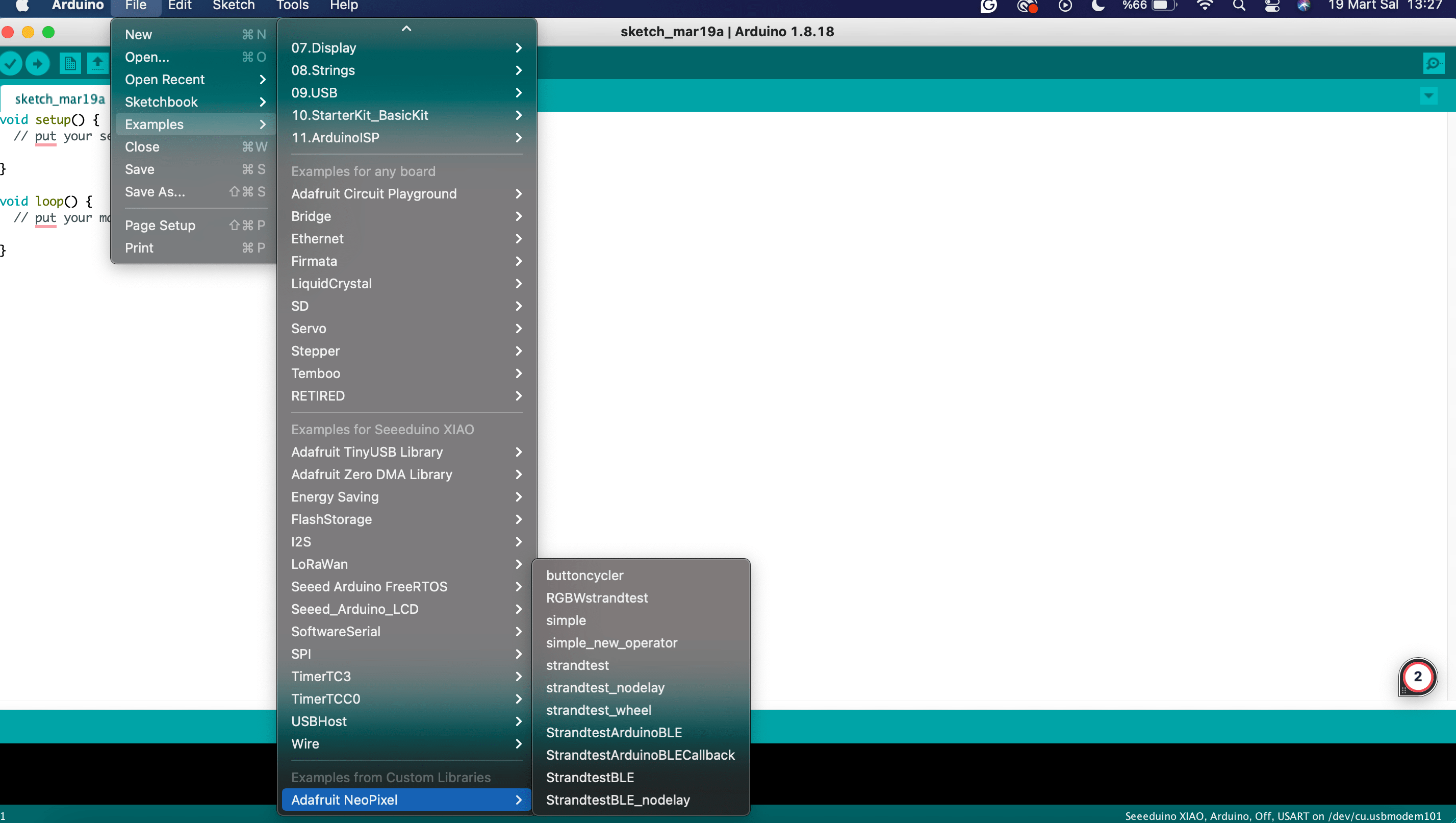
For controlling the LED I combined the button codes from the embedded programming week and example "Adafruit NeoPixel" codes.
Here you can find codes for FSR and button.
- Similar to the button code, to turn on the LED, value must be bigger than 1022.
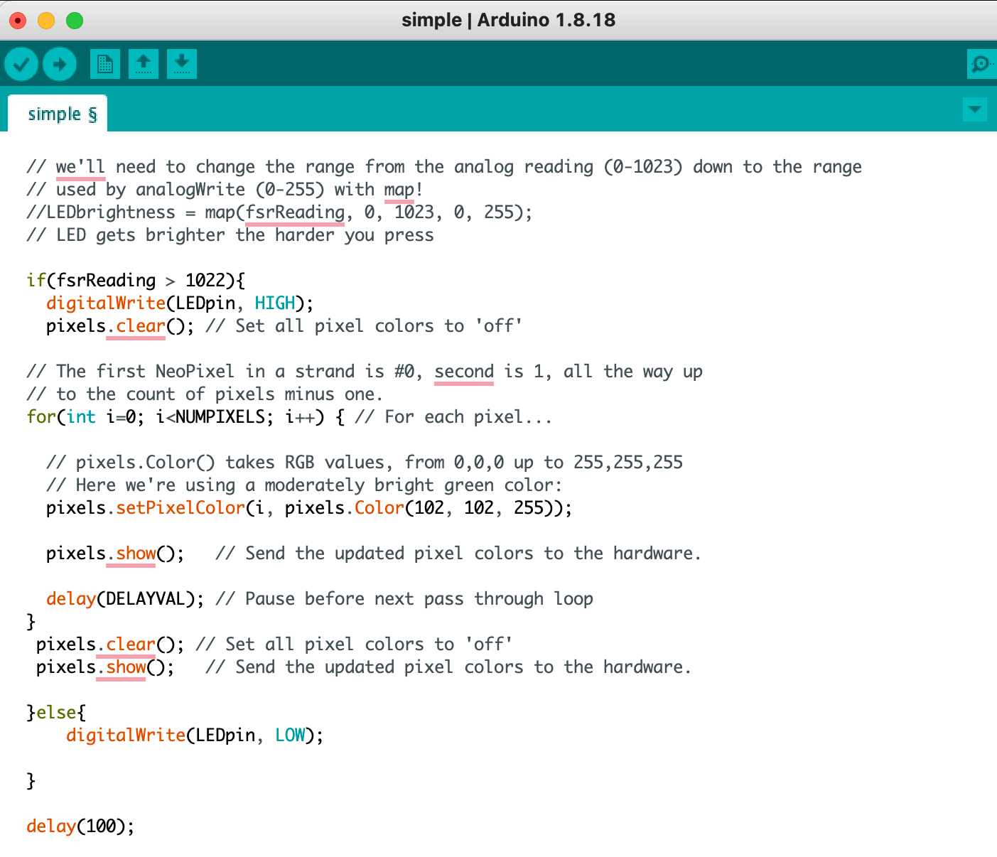
- pixels.setPixelColor(i, pixels.Color(102, 102, 255)) —-- This line set LED color.
- pixels.clear(); --- use for turning off the LEDs, when all of them turn on.
6. Testing RGB LED
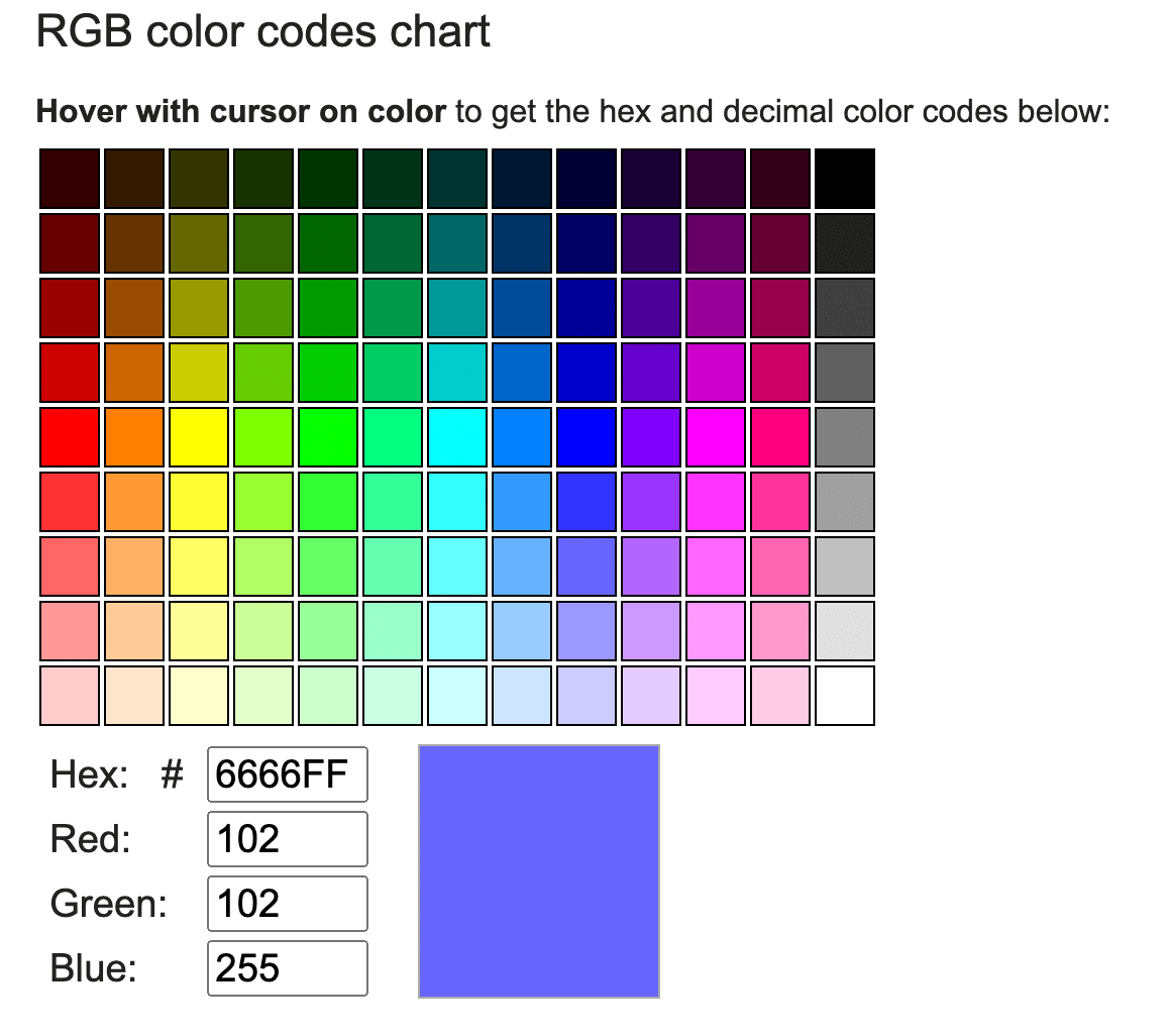
For testing I changed the colors of the LEDs. I picked one of the blue shades on the RGB color generator.
7. Implementation to the Final Project
I designed cylinders that I would place inside the lighting modules. I made the heights of the cylinders equivalent to the height of the lighting modules and made gaps in the centre for the cables to pass through. To speed up the process, I printed the cylinders on a bamboo printer.
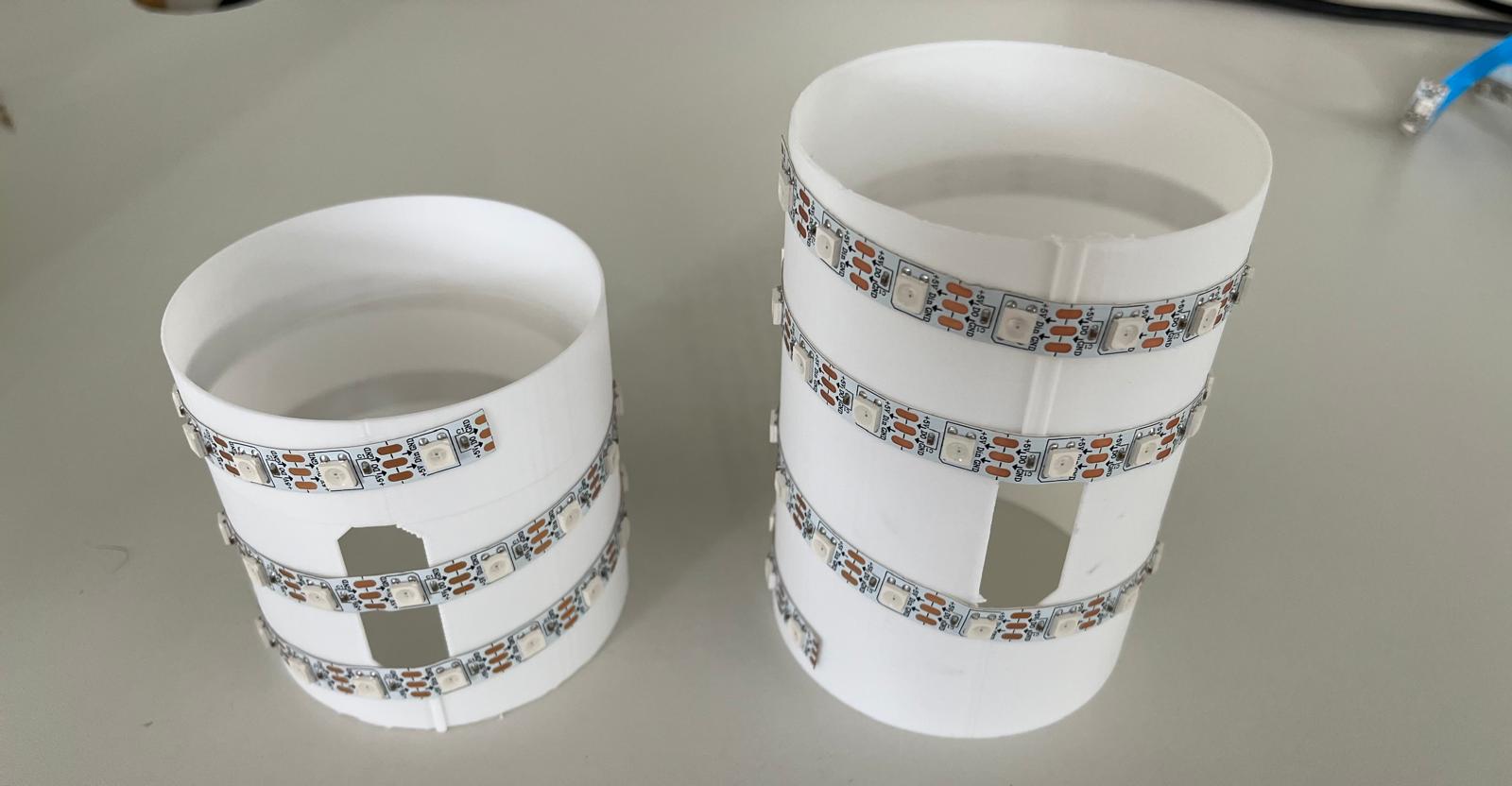
Firstly, I soldered the pogo pins on one cover to the LED, then I glued the cylinder to the base of the lighting module with hot glue and placed the pogo pins on the other cover to the other end of the LED. Green goes to signal, black goes to ground and yellow goes to 5v on the LED.
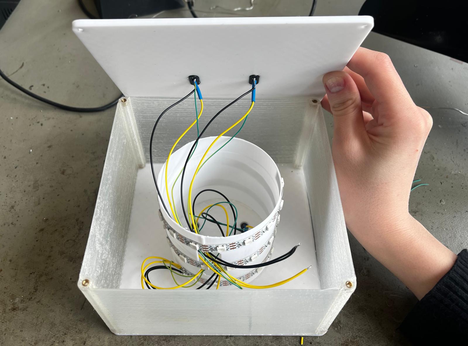
Also, the other end of the cables is connected to the pogo pin. The signal and electricity from the PCB and battery from the main module are transferred to the lighting modules via pogo pins.
I used following code for programming the LED and the touch sensor.
#include

const int SOFT_POT_PIN = A0; // Pin connected to softpot wiper

const int GRAPH_LENGTH = 8; // Length of line graph


// Which pin on the Arduino is connected to the NeoPixels?
#define PIN        D5 // On Trinket or Gemma, suggest changing this to 1

// How many NeoPixels are attached to the Arduino?
#define NUMPIXELS 180 // Popular NeoPixel ring size


Adafruit_NeoPixel pixels(NUMPIXELS, PIN, NEO_GRB + NEO_KHZ800);

#define DELAYVAL 50 // Time (in milliseconds) to pause between pixels

int brightness =0 ;

int oldBrigthness = 0;

int colorG =0 ;
int colorR =0 ;
int colorB=0 ;

int tempValue = 0;


void setup()
{
Serial.begin(9600);
pinMode(SOFT_POT_PIN, INPUT);
pixels.begin(); // INITIALIZE NeoPixel strip object (REQUIRED)

}

void loop()
{
// Read in the soft pot's ADC value
int softPotADC = analogRead(SOFT_POT_PIN);
//Serial.println(softPotADC);
// Map the 0-1023 value to 0-40
int softPotPosition = map(softPotADC, 0, 4095, 0, GRAPH_LENGTH);
tempValue = map(softPotPosition, 0, GRAPH_LENGTH, 0, 255);
Serial.println(tempValue);

if (tempValue != 0){
brightness=tempValue;
if (tempValue < 33) brightness=0;

if(brightness!=oldBrigthness)ledStrip();

}


/*colorG = map(softPotADC, 0, 1023, 0, 255);
colorR = map(softPotADC, 0, 1023, 0, 255);
colorB = map(softPotADC, 0, 1023, 0, 255);*/

//delay(500);
}

void ledStrip() {
pixels.clear(); // Set all pixel colors to 'off'

// The first NeoPixel in a strand is #0, second is 1, all the way up
// to the count of pixels minus one.
for(int i=0; i< NUMPIXELS; i++) { // For each pixel...

// pixels.Color() takes RGB values, from 0,0,0 up to 255,255,255
// Here we're using a moderately bright green color:
pixels.setPixelColor(i, pixels.Color(brightness, brightness, brightness));

pixels.show();   // Send the updated pixel colors to the hardware.

}
oldBrigthness=brightness;
}
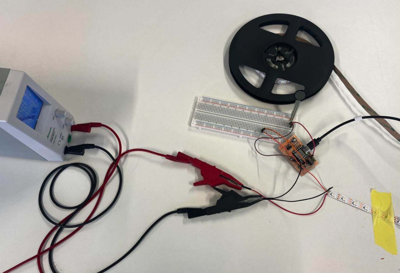
8. Testing power supply for group Assignment
Aim of the test: How does current affect the LED? I tested my LED connected to my PCB as an output device for the assignment. For the test, I used these components;
- Power supplier.
- Black and red cables for power supplier.
- My circuit design- It has RGB LED which can be controlled with a touch-sensitive resistor.
Steps of the first test;
- Voltage was around 5.
- Current was around 10
- I pressed the FSR.
Led worked as usual. I didn't observe any strange situation.
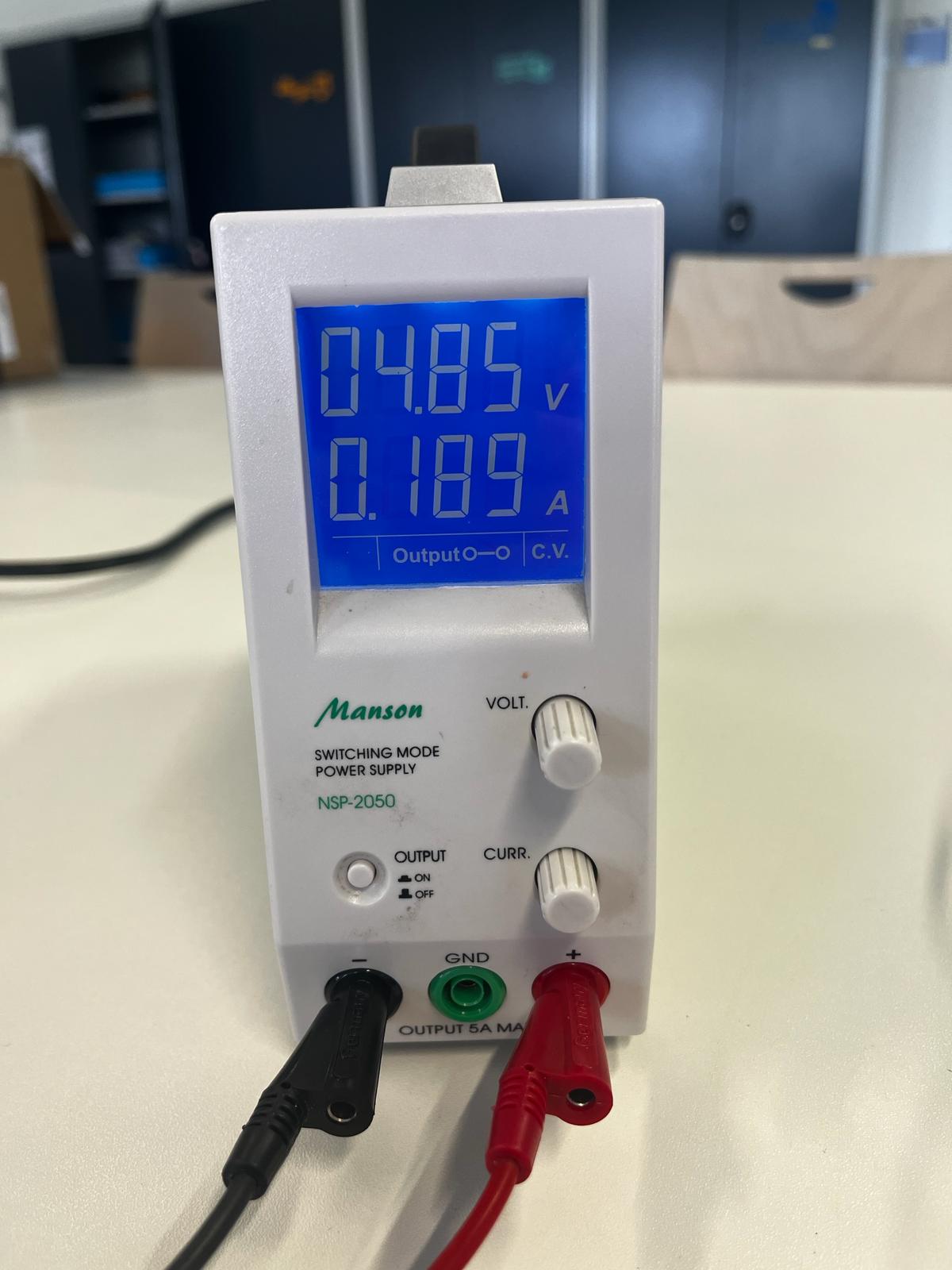
Steps of the second test;
- Voltage was around 5.
- I aimed to change the current for the circuit. Therefore I used the rotating switch of the supplier and I went up.
- I pressed the FSR.
LED worked as in the first test. I didn't observe any change.
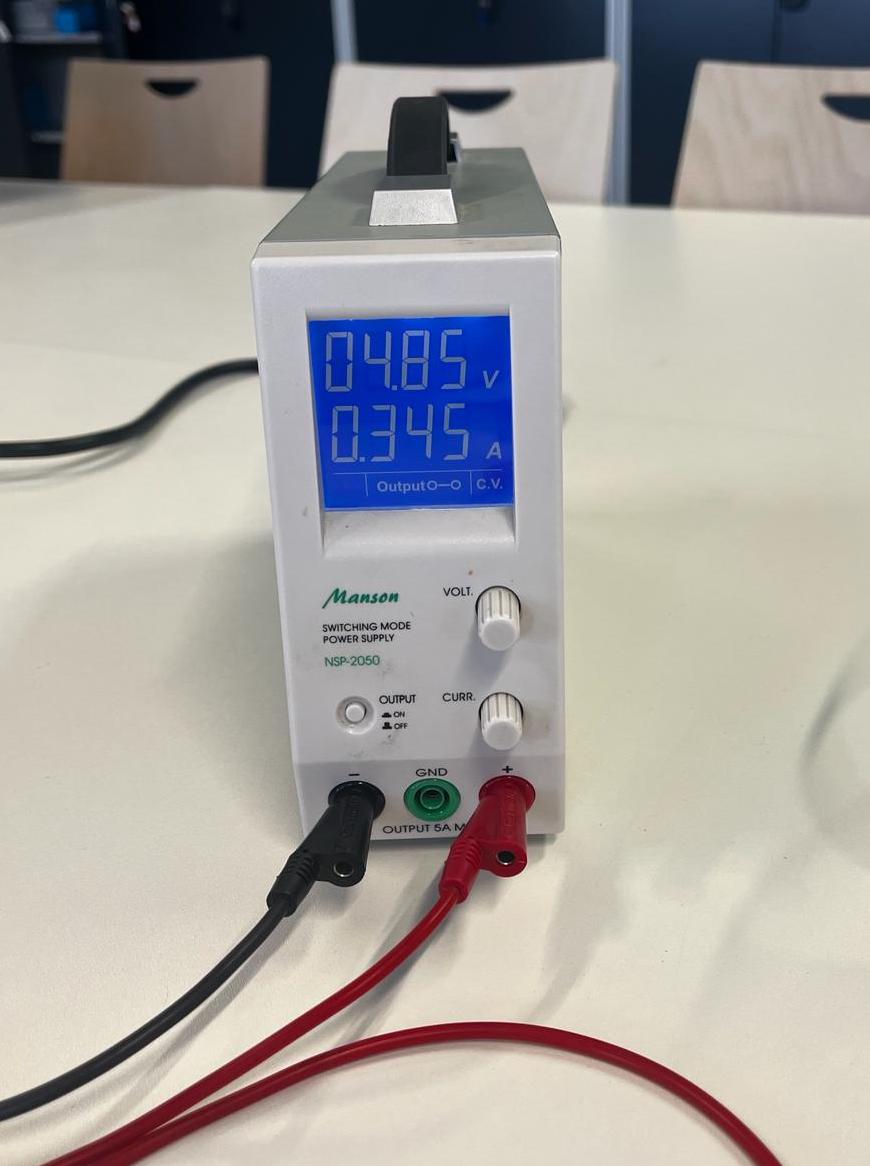
Result of test;
The current depends on how much power the circuit needs. The reason why I couldn't observe any change on the LED even if I tried to change the current on the power supplier, the need of voltage for the circuit is stable.
Power is the product of the current and the voltage. Voltage is fixed what changed is the current, affecting the total power. Setting the current on the supply sets the maximum you can withdraw, you will only see a change once you go below what the load needs