WEEK 6
Embedded Programing
Group Assignment:
- Browse through the data sheet for your microcontroller.
- Compare the performance and development workflows for other architectures.
Individual Assignment:
- Write a program for a microcontroller development board that you made, to interact (with local input &/or output devices).
- Communicate (with remote wired or wireless devices).
- Extra credit: connect external components to the board.
What Is Embedded Programing?
Embedded coding is used to program small computers called embedded systems. These embedded systems are found in many devices around us, like smartphones, cars, washing machines. Embedded coding is about making devices smart and capable of performing specific tasks reliably and efficiently.
Basics of Programing
Firstly, I opened the Arduino IDE to write my codes and transfer it to my PCB. There are two main elements which is crucial to understand the coding. 1. void setup() , 2. void loop().
- 1. void setup(); In Arduino, the setup() function is called once when the program starts, and it's where you typically configure things that need to be set up before the main part of the program runs.
- 2. void loop(); is a function in the Arduino programming language that contains the main body of your program. It's called repeatedly after the setup() function runs, allowing your Arduino to continuously execute a series of instructions or tasks.
Connecting to PCB
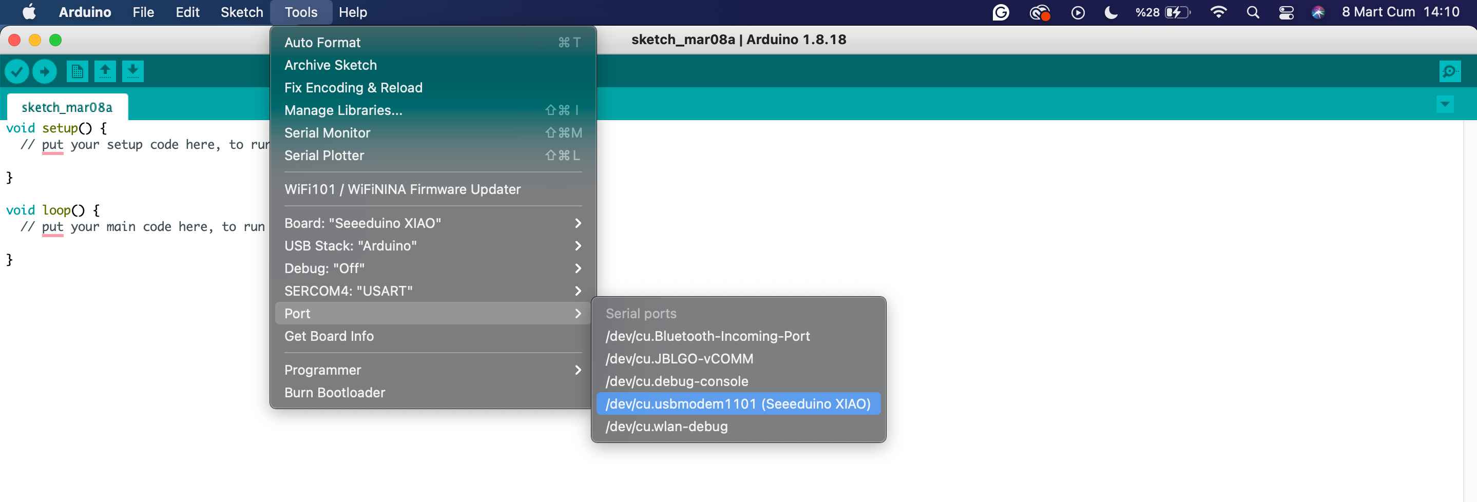
To transfer the codes from Arduino IDE to my PCB, I need to connect them. Thus, I followed this direction; Tools —- Port —- Seeeduino XIAO.
Testing PCB for LED
Before writing and transferring my codes I want to test my PCB with a ready code. Thus, I followed this direction; File —- Examples —-> Basics —-> Blink. I clicked the arrow on the interface on left top corner side to transfer my code. When it is transferred, I saw that my PCB's LED is blinking.
void setup() {
// initialize digital pin LED_BUILTIN as an output.
pinMode(8, OUTPUT);
// My LED connected to pin8. Thus I put 8 as pin number, it can be used to send voltage.
}

// the loop function runs over and over again forever
void loop() {
digitalWrite(8, HIGH);   // turn the LED on (HIGH is the voltage level)
delay(1000);                       // wait for a second
digitalWrite(8, LOW);    // turn the LED off by making the voltage LOW
delay(1000);                       // wait for a second
}
Basically for turning on and off the LED ;
- To control the LED ---- Put pin number which is connected to the LED as an OUTPUT. This must be under "void setup" because it needs to be setup before the main part of the program runs.---- pinMode(8, OUTPUT).
- To turn on and off the LED, define the high and low voltage. These codes must be placed under "void loop ()" because It's called repeatedly. ---- digitalWrite(8, HIGH), digitalWrite(8, LOW).
- To make the turning on and off process sequentially, put the delay code between them. ---- delay(1000); We can change the duration of the delay by putting another value.
Testing PCB for Button
I followed similar process to test my button. File --- examples --- digital --- button. Again, to transfer my code, I clicked the arrow on the interface on left top corner side. When I pressed the button, I saw the LED turns off.
// constants won't change. They're used here to set pin numbers:
const int buttonPin = 0;     // the number of the pushbutton pin
const int ledPin =  8;      // the number of the LED pin

// variables will change:
int buttonState = 0;         // variable for reading the pushbutton status

void setup() {
// initialize the LED pin as an output:
pinMode(ledPin, OUTPUT);
// initialize the pushbutton pin as an input:
pinMode(buttonPin, INPUT);
}

void loop() {
// read the state of the pushbutton value:
buttonState = digitalRead(buttonPin);

// check if the pushbutton is pressed. If it is, the buttonState is HIGH:
if (buttonState == HIGH) {
// turn LED on:
digitalWrite(ledPin, HIGH);
} else {
// turn LED off:
digitalWrite(ledPin, LOW);
}
}
- To control the button --- Put pin number which is connected to the button.--- const int buttonPin = 0
- Defining the button state helps us control the LED status ----- (buttonState == HIGH)
- To associate the button and LED, use "if" and "else" statement.
- To associate the button and LED, use "if" and "else" statement.---- if (buttonState == HIGH); digitalWrite(ledPin, HIGH)---- means, if the button is high, open the LED.
- In any other situation, turn of the LED---- else {digitalWrite(ledPin, LOW)}
Understanding FSR
I decided to use a force sensitive resistor for my assignment. However, my knowledge on electronics almost on level zero :x Nevertheless, I wantted to try force sensitive sensor to create a interactive experience!
FSRs are sensors that allow you to detect physical pressure, squeezing and weight. They are simple to use and low cost. FSRs are basically a resistor that changes its resistive value (in ohms Ω) depending on how much it is pressed.
To build my circuit, firstly I tried understand how I can connect my PCB and the FSR.
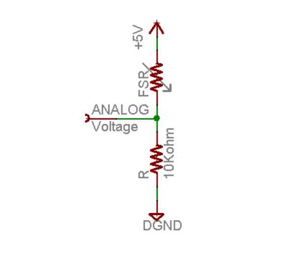
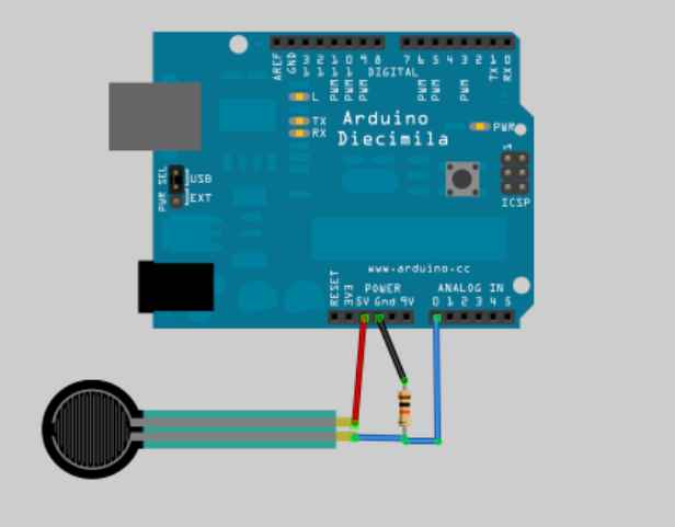
On the schema, I saw I need board, cables and 10 Kohm resistors. When I had all components, I started to try connect all component by help of the schema. I realized that, understand output number of the microcontroller is important to connect the cable right places. Because of that, I used that schema;
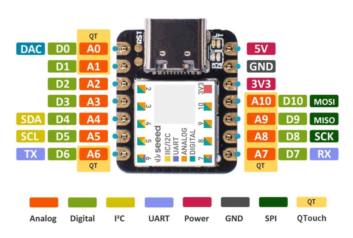
I learned that on the board gaps are connecting vertically and I can use this gaps from top to bottom direction. I found ground and 5V pin output number on the schema then I connected the cable.
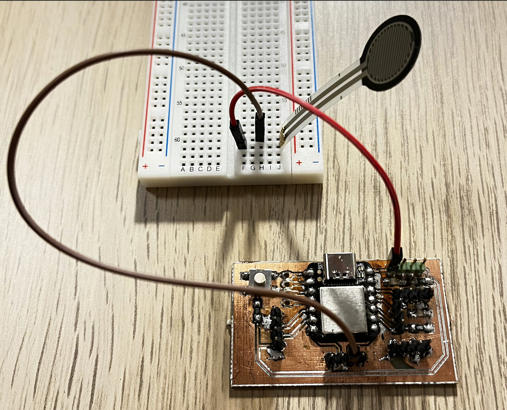
I aimed to change the intensity of the LED brightness with using resistor and the codes. I try to connect the 10K ohm resistors however it didn't work how I expected. Thus, I decided to not use the resistor.
When I couldn't stabilize the LED intensity with the resistors, I changed my aim to use FSR. I planed to use the FSR like button; When I press FSR, LED turns on. However, I needed to change the code according to this aim.
int fsrAnalogPin = A7; // FSR is connected to analog pin A7
int LEDpin = 8;        // Connect LED to digital pin 8 (PWM pin)
int fsrReading;        // Variable to store analog reading from the FSR
int LEDbrightness;     // Variable to store LED brightness level

void setup() {
	Serial.begin(9600);  // Initialize serial communication at 9600 baud rate
	pinMode(LEDpin, OUTPUT); // Set LEDpin as an output
}

void loop() {
	fsrReading = analogRead(fsrAnalogPin); // Read analog value from FSR connected to fsrAnalogPin
	Serial.print("Analog reading = "); // Print message to Serial monitor
	Serial.println(fsrReading); // Print the analog reading to Serial monitor

	// Check if FSR reading is greater than 1022 (threshold value)
	if (fsrReading > 1022) {
	digitalWrite(LEDpin, HIGH); // Turn on LED if FSR reading exceeds threshold
	} else {
	digitalWrite(LEDpin, LOW); // Turn off LED if FSR reading is below threshold
	}

	delay(100); // Delay for 100 milliseconds
}
By opening the Serial Monitor in the Arduino IDE, I can access messages sent from my PCB.
- Similar to the LED, I need to assign pin number for FSR, which is analog 7.
- Similar to the button code, to control the LED. It must be communicated with the sensor. So to turn on the LED, the value of "fsrReading" must be bigger than 1022.
- To turn off the LED, the value of "fsrReading" must be smaller than 1022.
- When I press the sensor, the serial number value increases over the 1022 thus LED turns on.
- I opened the serial monitor screen by clicking on the magnifying glass icon in the upper right corner of the interface.
I am adding the following video to see the use of serial monitor. This video contains the sensor and code I used during the electronics design week. But it visualises the use of serial monitor.