Introduction
This week’s assignment focuses on integrating an output device into our board. For my final project, I want to make controller that allows me to extrude plastic with the Massive Dimension pellet extruder, . For this I need to make a a board that has 3 digital signal outputs, one to control the steps (speed), one for direction, and one to enable the extruder.
Objectives
To control the motor , I referenced the Teknik Motor Clearpath user manual, this manual explains the motor can operate as a regular stepper motor, and the digital signals it expects its from 3v-24v meaning that an arduino or similar can control the motor.
We will need to generate 3 different signals from the arduino:
- Enable: This signal can be 0 or 1. To activate the motor, it must be set to 1.
- Direction: This signal can also be 0 or 1, where 0 rotates the motor clockwise and 1 rotates it counterclockwise.
- Step: This output toggles on and off. Each toggle represents one step, and the motor is configured to require 800 steps to complete a full rotation.
Here is the Diagram from the MDPE2
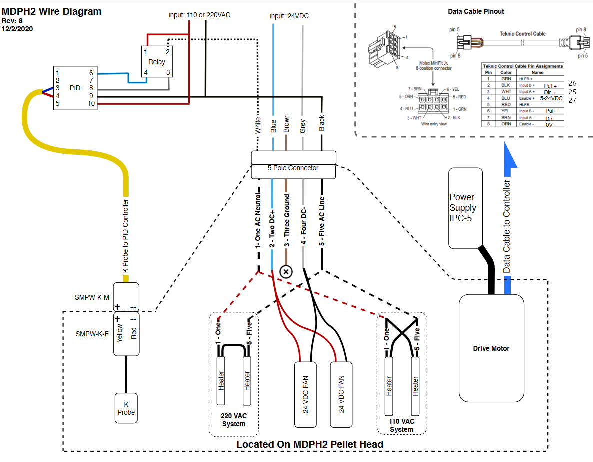
In this case we will use the Digital outputs as follows
- 25 : this Output will generate the steps by turning on and off repeatedly
- 26 : this Output if on will change the rotation direction of the extruder
- 27 : this Output has to be on to enable the extruder.
The goal is to achieve precise control over the motor’s Revolutions Per Minute (RPM) this will make it easier to calculate the flow (volume) on the extruder to calibrate for a toolpath.
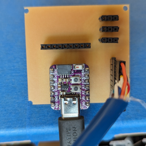
- Custom Board from previous week
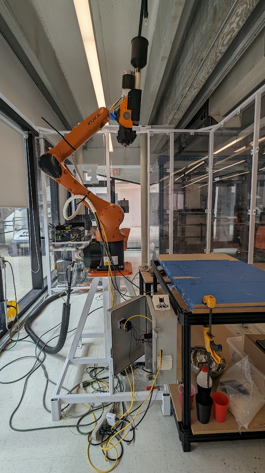
- Massive Dimension Pellet Extruder MDPH2: MDPH2 Pellet Head Extruder System
Process
I tried generating steps through a loop, manually toggling the step output relying on the clock of the microcontroller, also we keed the direction off as we want it to rotate clockwise, finally at the setup fucntion we turn on the enable output to make sure the extruder is enabled.
1
2
3
4
5
6
7
8
9
10
11
12
13
14
15
16
17
18
19
20
21
22
23
24
25
26
27
28
29
30
31
32
33
34
35
36
37
38
39
40
41
42
43
44
45
46
47
48
49
50
51
52
53
54
55
56
57
58
59
60
61
62
63
64
65
66
67
68
69
70
71
72
73
74
75
76
77
78
79
80
81
82
83
84
85
86
87
88
89
90
91
92
93
94
95
96
97
98
99
100
101
102
103
104
105
106
107
108
109
110
111
112
113
114
|
// extrudercontrol.ino
//
//
// Luis Pacheco 3/27/24
//
// This work may be reproduced, modified, distributed,
// performed, and displayed for any purpose, but must
// acknowledge this project. Copyright is retained and
// must be preserved. The work is provided as is; no
// warranty is provided, and users accept all liability.
//
#include <Arduino.h>
// Motor variables
int OutStep = 25;
int OutDir = 26;
int OutEnable = 27;
bool MotorEnable = false;
float MotorRev = 800;
float MotorSpeed = 0; // revolutions per minute
unsigned long LastRunTime = 0;
unsigned long currentMotorTime = 0;
unsigned long previousMotorTime = 0;
long motorInterval = 0.1;
// Rotary encoder variables
#define SPIN_A 2
#define SPIN_B 4
#define SPIN_BUTTON 15
volatile bool sturnedCW = false;
volatile bool sturnedCCW = false;
static int svalue = 0;
int DEBONCE_TO = 150;
unsigned long sdebounceTime = 0;
bool slastWasCW = false;
bool slastWasCCW = false;
void setup() {
Serial.begin(115200);
// MOTOR setup
pinMode(OutDir, OUTPUT);
pinMode(OutStep, OUTPUT);
pinMode(OutEnable, OUTPUT);
digitalWrite(OutEnable, HIGH); // activate extruder motor
digitalWrite(OutDir, HIGH); // Set direction
Serial.println("Motor setup OK");
currentMotorTime = millis();
previousMotorTime = millis();
// Motor Encoder setup
pinMode(SPIN_A, INPUT_PULLUP);
pinMode(SPIN_B, INPUT_PULLUP);
pinMode(SPIN_BUTTON, INPUT_PULLUP);
attachInterrupt(digitalPinToInterrupt(SPIN_B), scheckEncoder, CHANGE);
Serial.println("Reading from encoder: MOTOR ");
}
void loop() {
// motor control logic here
if (MotorEnable && MotorSpeed != 0) {
currentMotorTime = millis();
float StepPerMillis = MotorRev * MotorSpeed / 30000000;
float MillisPerStep = 1 / StepPerMillis;
digitalWrite(OutStep, HIGH);
delayMicroseconds(MillisPerStep);
digitalWrite(OutStep, LOW);
delayMicroseconds(MillisPerStep);
}
// Rotary encoder logic for motor speed control
if (sturnedCW) {
svalue++;
MotorSpeed = svalue * 25; // Example: Adjusting speed with each CW turn
sturnedCW = false;
slastWasCW = true;
sdebounceTime = millis();
}
if (sturnedCCW) {
if (MotorSpeed > 0) {
svalue--;
MotorSpeed = svalue * 25; // Example: Decreasing speed with each CCW turn
}
sturnedCCW = false;
slastWasCCW = true;
sdebounceTime = millis();
}
// Reset motor speed to zero if encoder button is pressed
int sbtnState = digitalRead(SPIN_BUTTON);
if (sbtnState == LOW && millis() - sdebounceTime > DEBONCE_TO) {
MotorSpeed = 0;
sdebounceTime = millis();
}
}
void scheckEncoder() {
if ((!sturnedCW) && (!sturnedCCW)) {
int spinA = digitalRead(SPIN_A);
delayMicroseconds(1500); // Debounce delay
int spinB = digitalRead(SPIN_B);
if (spinA == spinB) {
sturnedCW = !slastWasCCW;
sturnedCCW = slastWasCCW;
} else {
sturnedCW = slastWasCW;
sturnedCCW = !slastWasCW;
}
}
}
|
This method, however, led to several issues:
- Introducing delays in the loop affected step timing and, consequently, RPM accuracy.
- As code complexity increases and depending on the microprocessor’s speed, loop execution may slow down, further impacting RPM precision. This method of manual step generation is known as “Bit Banging.”
After exploring PWM (Pulse Width Modulation) and encountering limitations related to its fixed frequency, I discovered the ESP32 allows for PWM frequency adjustment. This capability enables consistent RPM control, regardless of main loop execution time or added delays, as the frequency can be dynamically altered. Ill imlement this on the final project.
Conclusion
Utilizing the ESP32’s hardware features for step control, as opposed to bit banging, significantly can improve the project. It allows for the addition of various inputs, outputs, networking features, etc., without compromising the precision or consistency of the extruder’s RPM. This board will later be useed on week 10 and the final project
Files:
Files