Introduction
This week’s task was to design our own PCB using an EDA (Electronic Design Automation) software. My choice was Fritzing for its beginner-friendly interface and Kicad, influenced by this week’s support video. While I’m impressed with Kicad’s capabilities and see benefits in migrating from Fritzing, Fritzing’s breadboard view offers substantial advantages for beginners in prototyping.
Objectives
- Design the same board in both Fritzing and Kicad, mill them, and compare the experiences.
- Fritzing
- Kicad
- Bantam Tools Desktop CNC (formerly Othermill)
- 1/64” flat end mill
- Mods for G-code generation
- Inkscape for file editing
Fritzing Process
Starting in Fritzing was straightforward. I planned my inputs and outputs using the breadboard view for a clear visual prototype, which aids in later assembly:

Moving to the PCB view, I connected components as if solving a puzzle, inspired by interactive games like Virtual Circuit Board:
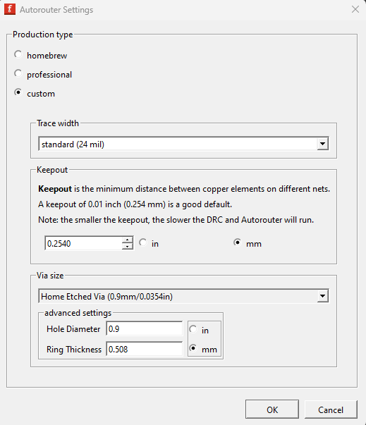
Some key things to consider are to use 24 mil traces, also I try to keep .25 mm at minimim of clearance between copper traces.
Here is a more detailed post
also here are the auto tracer settings:
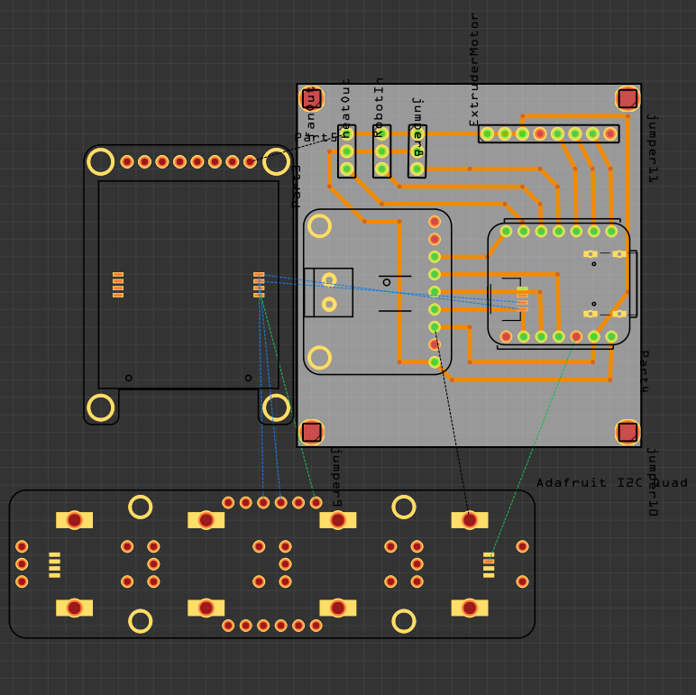
Then I can run the rule checker
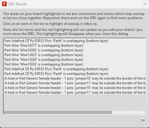
As some of this parts are not standard some issues came up on the rule checker but nothing to worry about.
For creating drill files and adjusting parameters, I edited the designs in Inkscape, notably inverting the file for correct trace orientation:
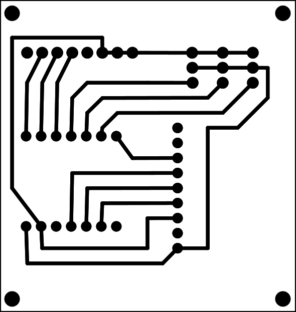
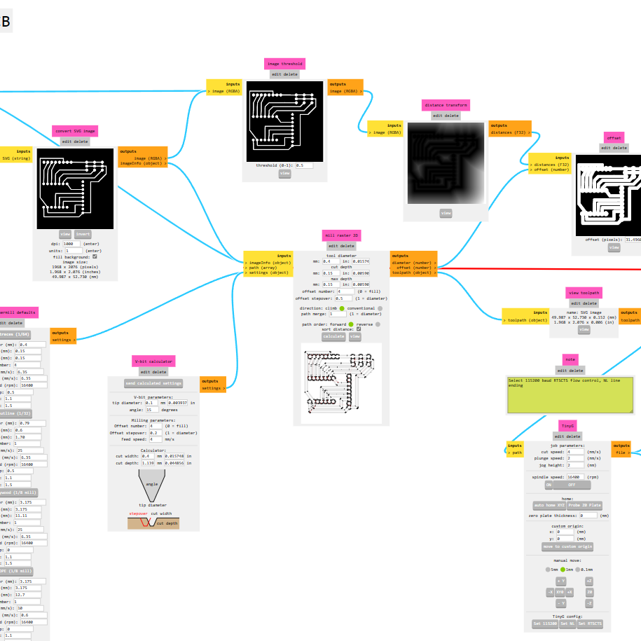
Using Mods, I generated the G-code tailored for the Bantam Tools CNC:
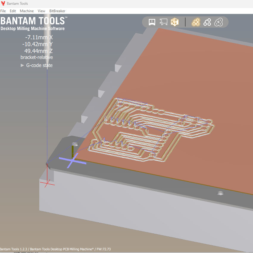
The board was then milled using the Bantam Tools software:

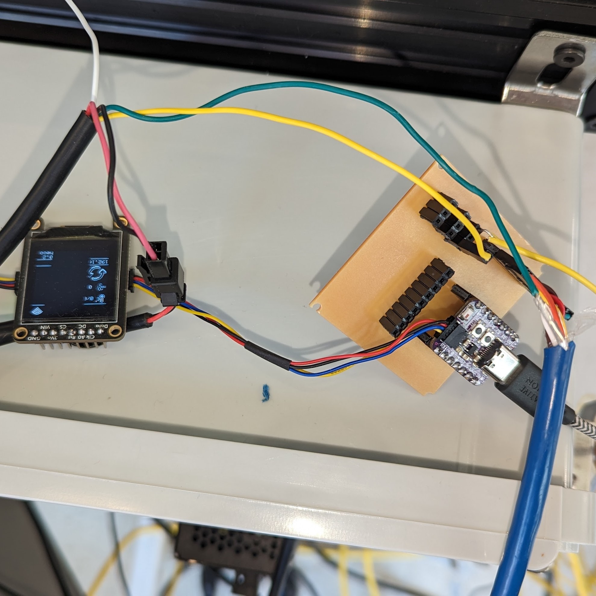
Soldered and tested
Fritzing Conclusion
Fritzing’s limitations include handling complex circuits and requiring Inkscape for file adjustments. However, its integration with Adafruit libraries and the bidirectional update feature between PCB and breadboard views simplifies the prototyping process.
Kicad Process
I began by following a helpful tutorial and used the Quentorres Kicad file as a starting point. Initially, Kicad felt more daunting, especially the schematic editor. After cleaning the design by removing unused elements and adding the same connectors I’m using in Fritzing, I proceeded to the PCB editor for tracing
I used the default rule settings:
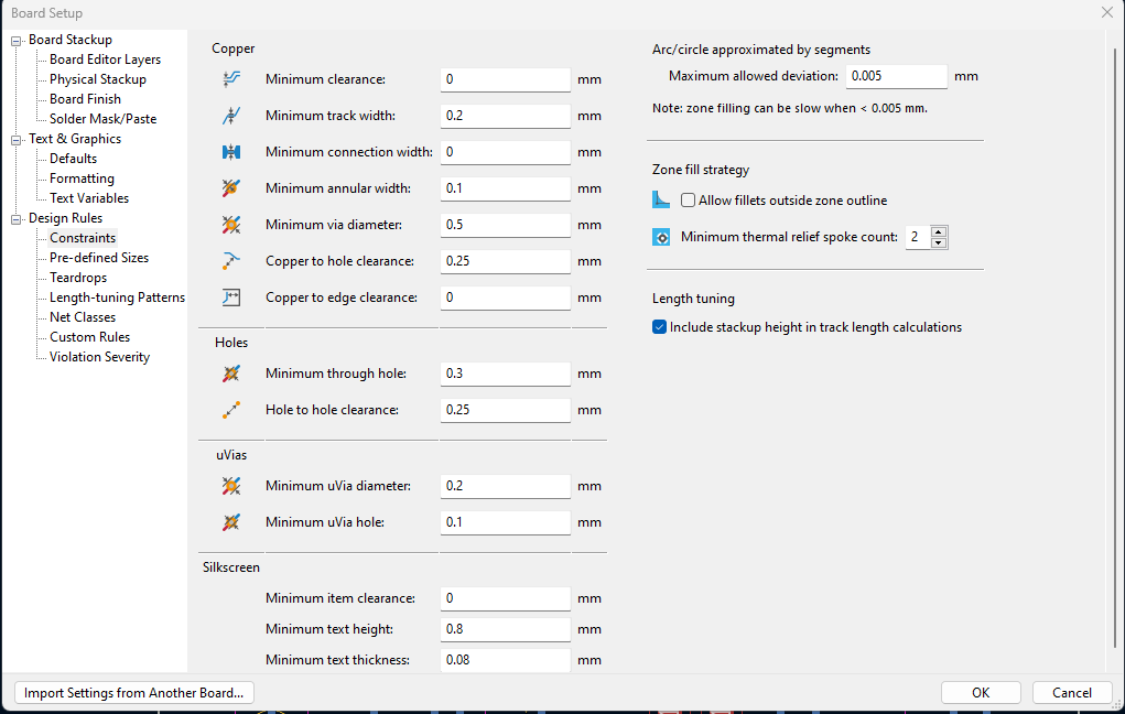

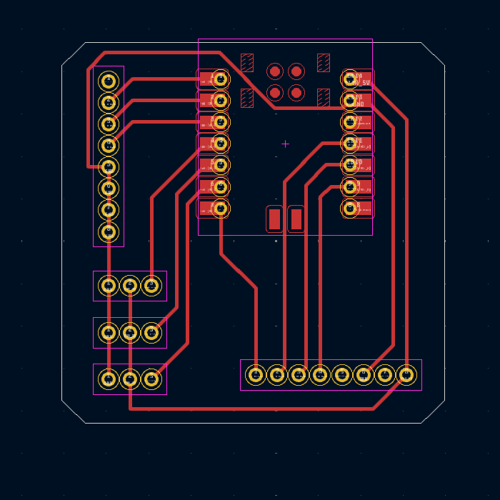
after that you can check your traces with the design rule checker:
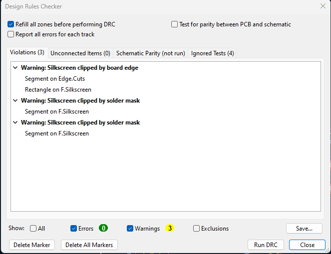
As you can see I had some warnings but nothing to be worried about.
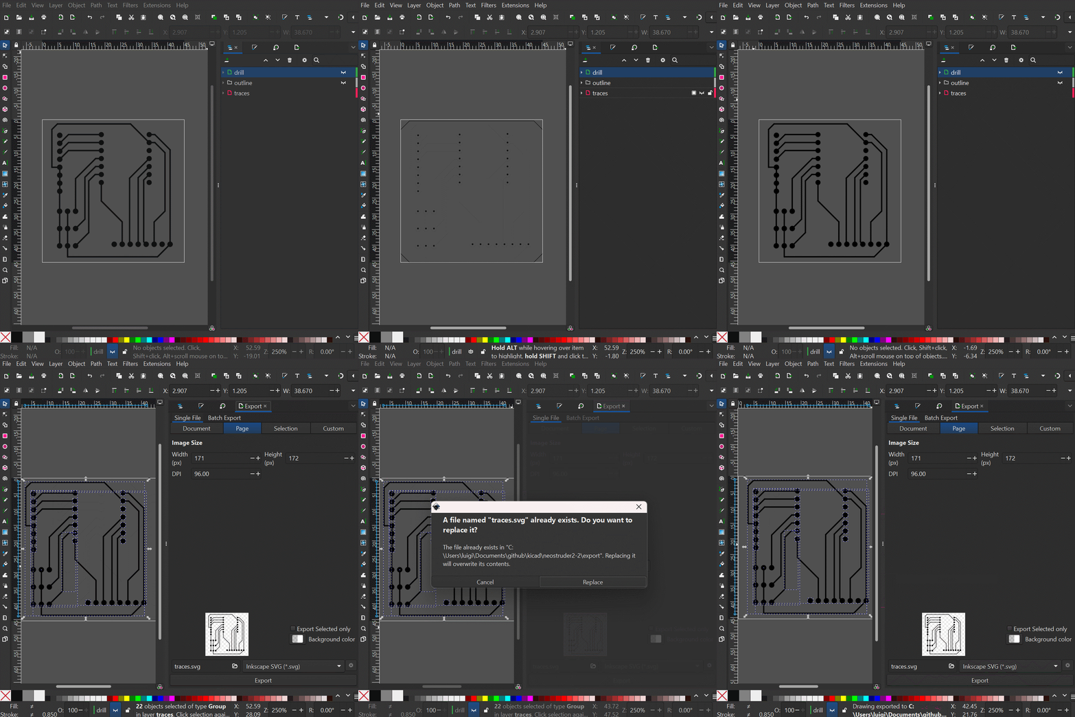
I exported the design to SVG and edited it on Inkscape:
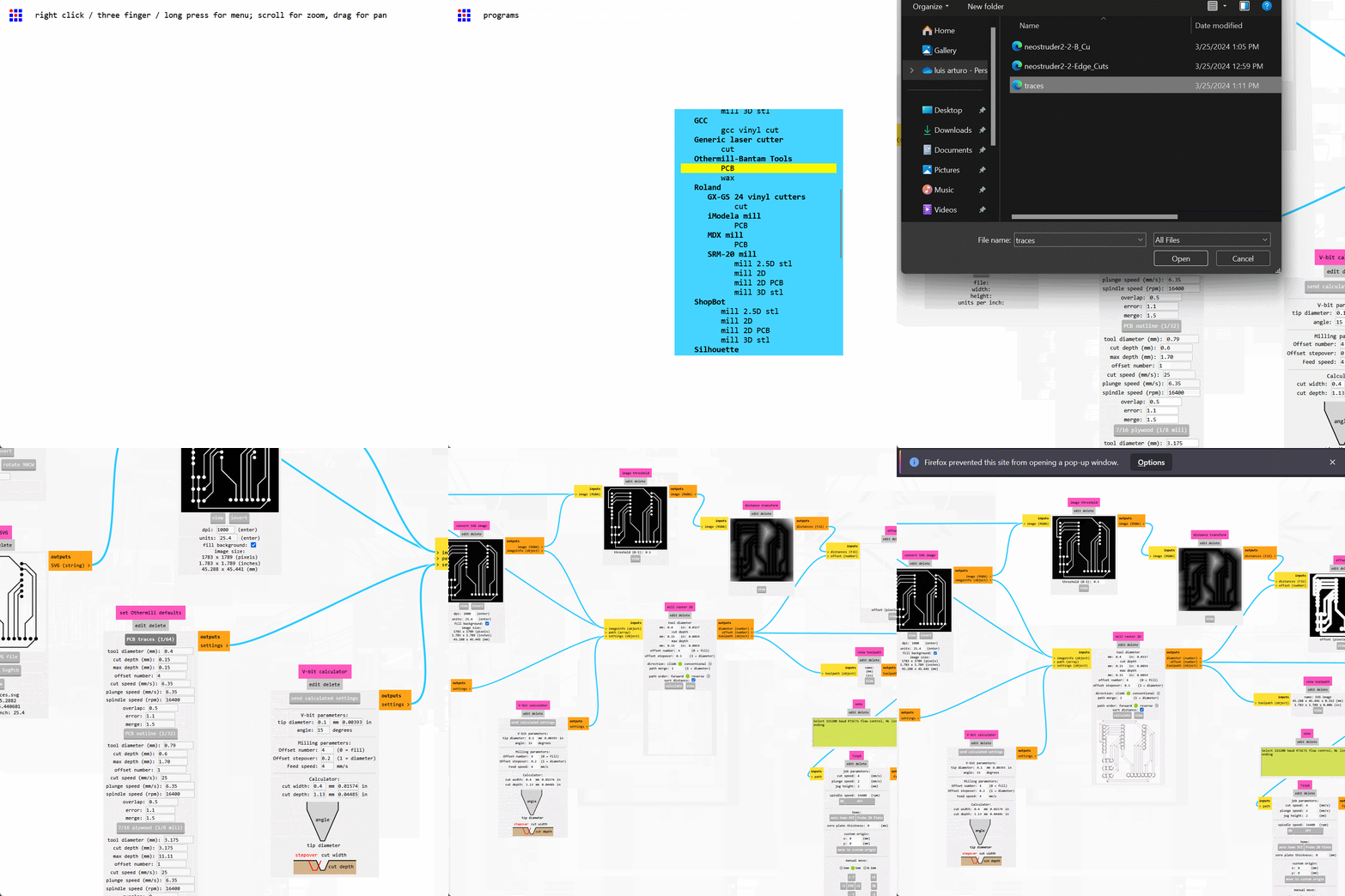
Finally, generated G-code on Mods:
Finally, the board was milled:

Kicad Conclusion
Kicad is powerful, though incorporating a workflow from PCB back to the schematic would better suit my process. Being able to import Adafruit footprints from Fritzing or Eagle would be really helpful; I still need to test this. Starting with Fritzing for breadboard prototyping and moving to Kicad for production seems like a good approach. Both of them seem to require some preprocessing and cleaning in Inkscape before being able to make the drill files. Kicad does, however, make it easier to add customized components, text, etc. Having used Fritzing for a couple of years now, I think it’s worth it to give Kicad a shot.