Week06 Group Assignmnet - Compare Various Microcontrollers
micro:bit
The micro:bit is an easily programmable Single Board Computer (SBC) that contains an application processor with a variety of on-chip peripherals. Detailed information can be found at the hardware introduction page.
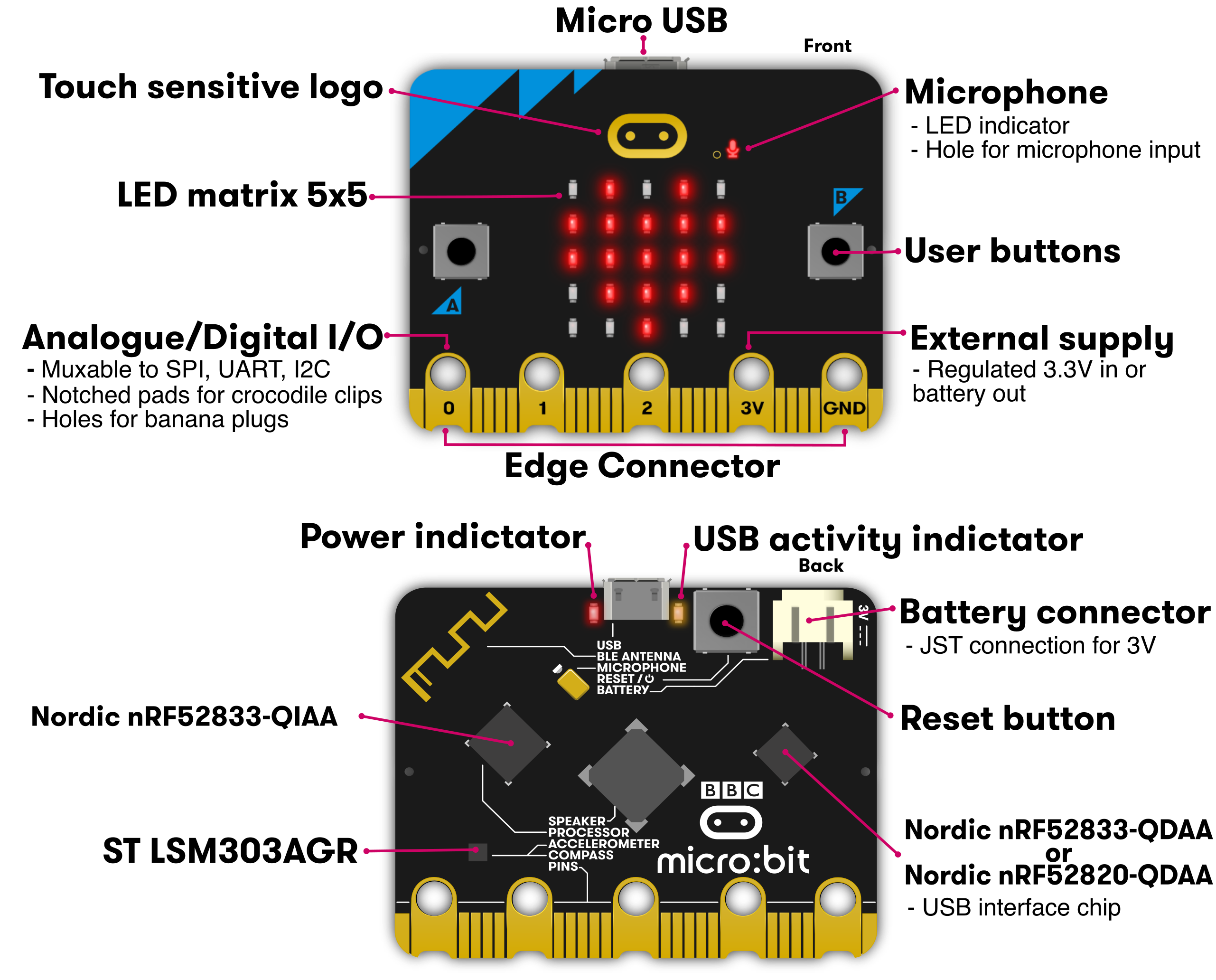
Basic specs of the micro:bit hardware
-
nRF52 Application Processor
- Model: Nordic nRF52833
- Core variant: Arm Cortex-M4 32 bit processor with FPU
- Flash ROM: 512KB
- RAM: 128KB
- Speed: 64MHz
- Debug: SWD, J-Link/OB
-
Buttons:
- 2 tactile user buttons, 1 tacktile system buttom
-
GPIO Pins:
- 19 GPIO pins
- 2 for I2C interface
- 6 for display/light sensoing
- 2 for button
- 3 simultaneous PWM channels
- 1 serial TX/RX channel
- 6 for analog input
- 3 for optional SPI interface
- 3 simultaneous touch sensing inputs
-
Accelerometer and Magnetometer:
- Model: LSM303AGR
- 3 magnetic field and 3 acceleration axes, 2/4/8/16g ranges
-
Temperature Sensor:
- Type: on-core nRF52
- Sensing range: -40℃ .. 105℃
-
LED Matrix:
- Type: minature surface mount red LED
- Physical structure: 5x5 matrix
- Intensity control: Software controlled up to 255 steps
- Sensing: ambient light estimation via software algorithm
- Sensing Range: TBC, 10 levels from off to full on
-
Bluetooth:
- Stack: Bluetooth 5.1 with Bluetooth Low Energy(BLE)
- Band: 2.4GHz ISM (Industrial, Scientific and Medical) 2.4GHz..2.41GHz
- Channels: 50 2MHz channels, only 40 used (0 to 39), 3 advertising channels (37,38,39)
- Sensitivity: -93dBm in Bluetooth low energy mode
- Tx Power: -40dBm to 4dBm
- Role: GAP Peripheral & GAP Central
- Congestion avoidance: Adaptive Frequency Hopping
- Profiles: BBC micro:bit profile
-
Power:
- Operating range: 1.8V .. 3.6V
- Operating current (USB and battery): 300mA max
- On-board Peripherals budget: 90mA
- Battery connector: JST S2D-PH-SM4-TB
- Max current provided via edge connector: 190mA
Programming micro:bit
Micro:bit can be programmed by using the online editor(MakeCode), Mu Editor and some other editors.
The beginner friendly Web based visual block programming environment is developed by Microsoft. There're lots of examples and tutorials provided for studing and exploring the functionality of the board.
We did a little interaction program using MakeCode, the steps are documented below:
-
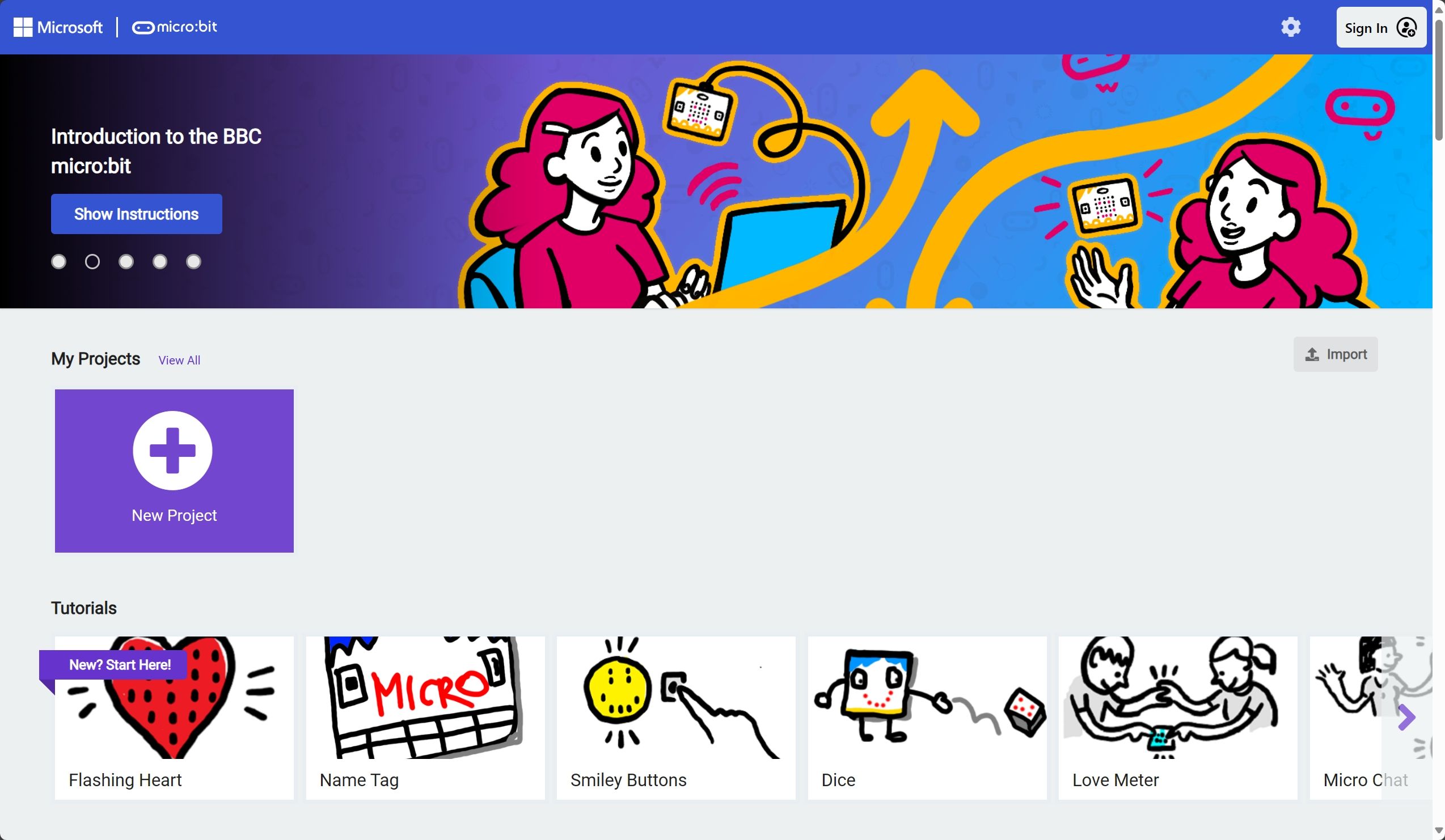
Go to https://makecode.microbit.org/, click
Open New Projectand select the programming language, here we chosed block programming.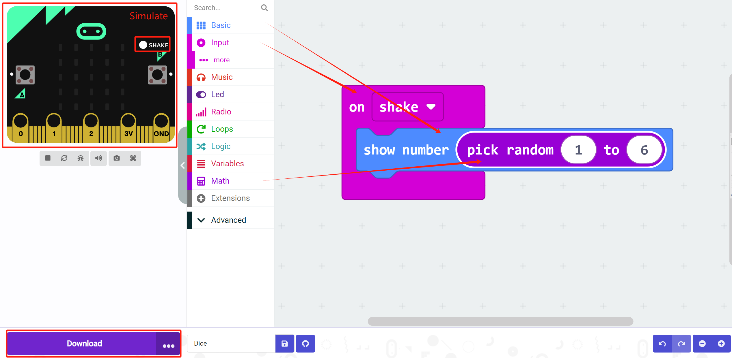
-
The
on shakeblock runs code when you shake the micro:bit. From theBasiccategory, get ashow numberblock and place it inside theon shakeblock to display a number. -
Press the white
SHAKEbutton on the micro:bit on-screen simulator, or move your cursor quickly back and forth over the simulator. -
But we don't want to show 0 on our dice all the time. From the
Math Toolboxcategory, drag apick randomblock and drop it into theshow numberblock replacing the 0. -
A typical dice shows values from 1 to 6 dots. So, in the
pick randomblock, change the minimum value to 1 and the maximum value to 6. -
Press the white
SHAKEbutton again on the micro:bit simulator. -
Download!
ATmega328p
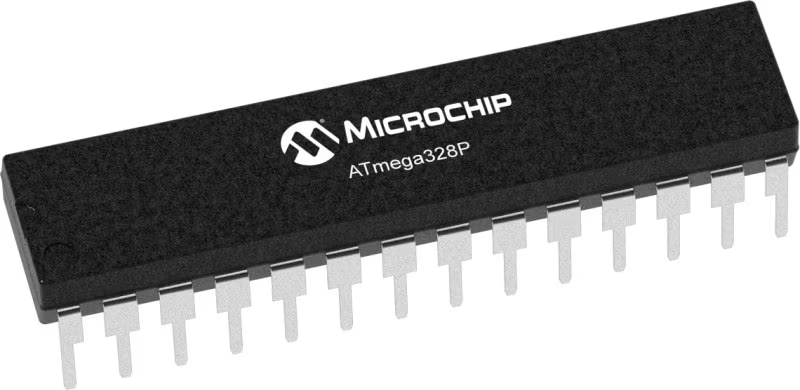
The ATmega328p is a high performance, low power AVR® 8-bit microcontroller, it is used as the core of the widely used Arduino Uno development borad. Some basic specs are listed below, more information can be found on the Microchip product page and its datasheet.
Specs
- High performance, low power AVR® 8-bit microcontroller
- 32KB ISP Flash memory
- 1024B EEPROM
- 2KB SRAM
- 23 general purpose I/O lines
- serial programmalble USART
- byte-oriented Two-Wire serial interface (I2C)
- SPI serial port
- 6-channel 10-bit A/D converter (8-channels in TQFP and QFN/MLF packages)
- Operating voltage:
- 2.7V - 5.5V
- Temperature range:
- Automotive temperature range: -40℃ to +125℃
- Speed grade:
- 0 to 8MHz at 2.7 to 5.5V (automotive temperature range: -40℃ to +125℃)
- 0 to 16MHz at 4.5 to 5.5V (automotive temperature range: -40℃ to +125℃)
- Low power consumption
- Active mode: 1.5mA at 3V - 4MHz
- Power-down mode: 1μA at 3V
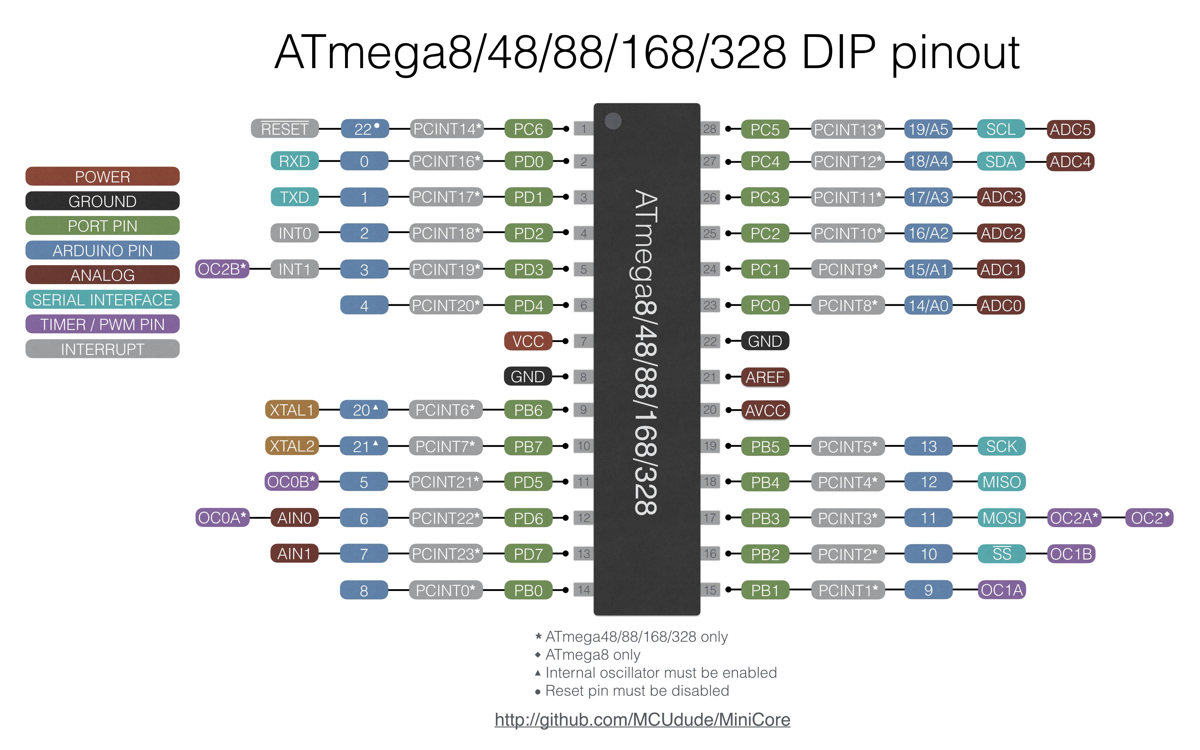
Pinout reference of ATmega328p DIP package from an alternative Arduino Core Minicore
Programming ATmega328p
The Arduino Uno comes with the USB serial interface that can be use to upload program from the computer. But the ATmega328p chip itself doesn't have that, and it needs a programmer to upload the program to the board.
Since the Arduino Uno uses the ATmega328p as its microcontroller, the Arduino IDE and its library can be used to write ATmega328p compatible code. The only difference is that the Arduino Uno has a 16MHz external crystall oscillator connected to the chip and the chip is running at a different speed if we only use the 8MHz internal oscillator of the ATmega328p itself.
According to the documentation from Arduino, we can load a diffrent board configuration for the ATmega328p to write code for the ATmega328p without the external oscillator, and we can use another Arduino Uno to act as the programmer to upload code to the chip, as some of us tried on week04 and this week's personal assignment.
Arduino Uno
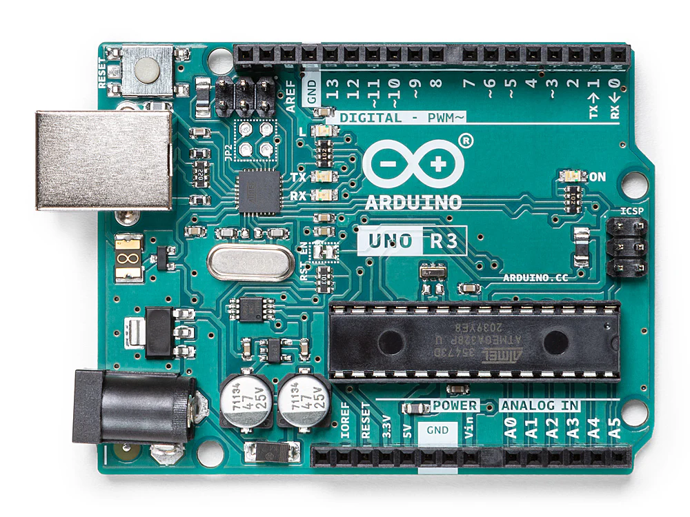
Arduino Uno is a microcontroller board based on the ATmega328P (datasheet). It has 14 digital input/output pins (of which 6 can be used as PWM outputs), 6 analog inputs, a 16 MHz ceramic resonator (CSTCE16M0V53-R0), a USB connection, a power jack, an ICSP header and a reset button. It contains everything needed to support the microcontroller; simply connect it to a computer with a USB cable or power it with a AC-to-DC adapter or battery to get started.
Below is the pin definition for the board:
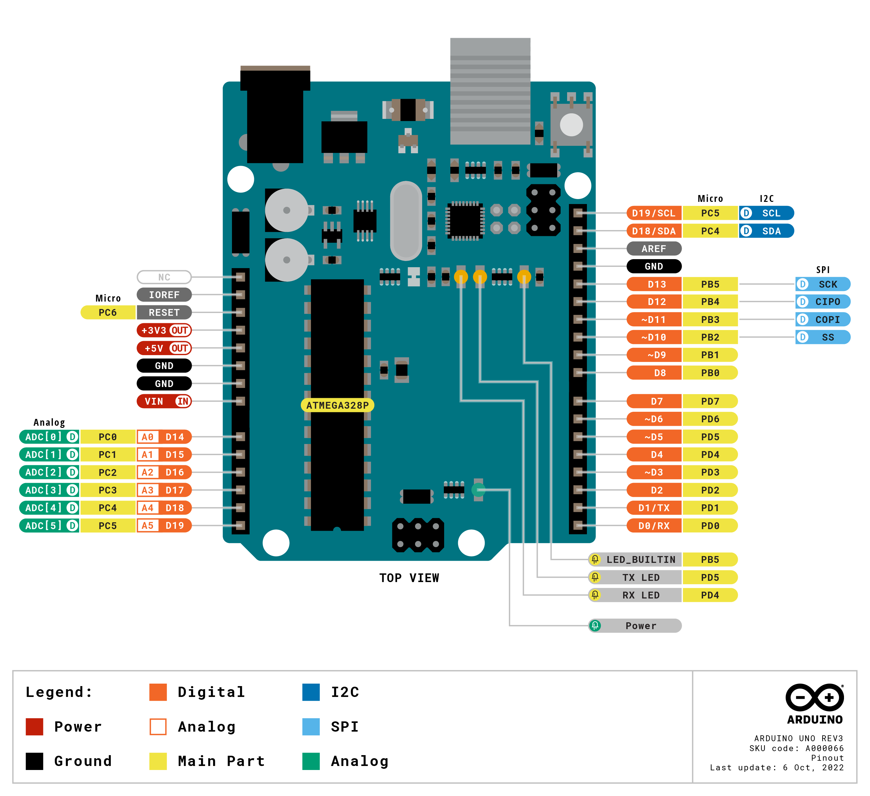
The PDF of the full pinout the board can be found here.
The PCB schematics can be found here.
The datasheet can be downloaded here.
Tech specs of the Arduino Uno
- Microcontroller: ATmega328P
- Operating Voltage: 5V
- Input Voltage (recommended): 7-12V
- Input Voltage (limit): 6-20V
- Digital I/O Pins: 14 (of which 6 provide PWM output)
- PWM Digital I/O Pins: 6
- Analog Input Pins: 6
- DC Current per I/O Pin: 20 mA
- DC Current for 3.3V Pin: 50 mA
- Flash Memory: 32 KB (ATmega328P) of which 0.5 KB used by bootloader
- SRAM: 2 KB (ATmega328P)
- EEPROM: 1 KB (ATmega328P)
- Clock Speed: 16 MHz
- LED_BUILTIN: 13
- Software: Arduino IDE, Arduino CLI, Web Editor
Programming the Arduino Uno
Below we tried to use the Arduino Uno to make a flashing LED, the steps are:
-
Download the latest version of the Arduino IDE, from https://www.arduino.cc/en/software.
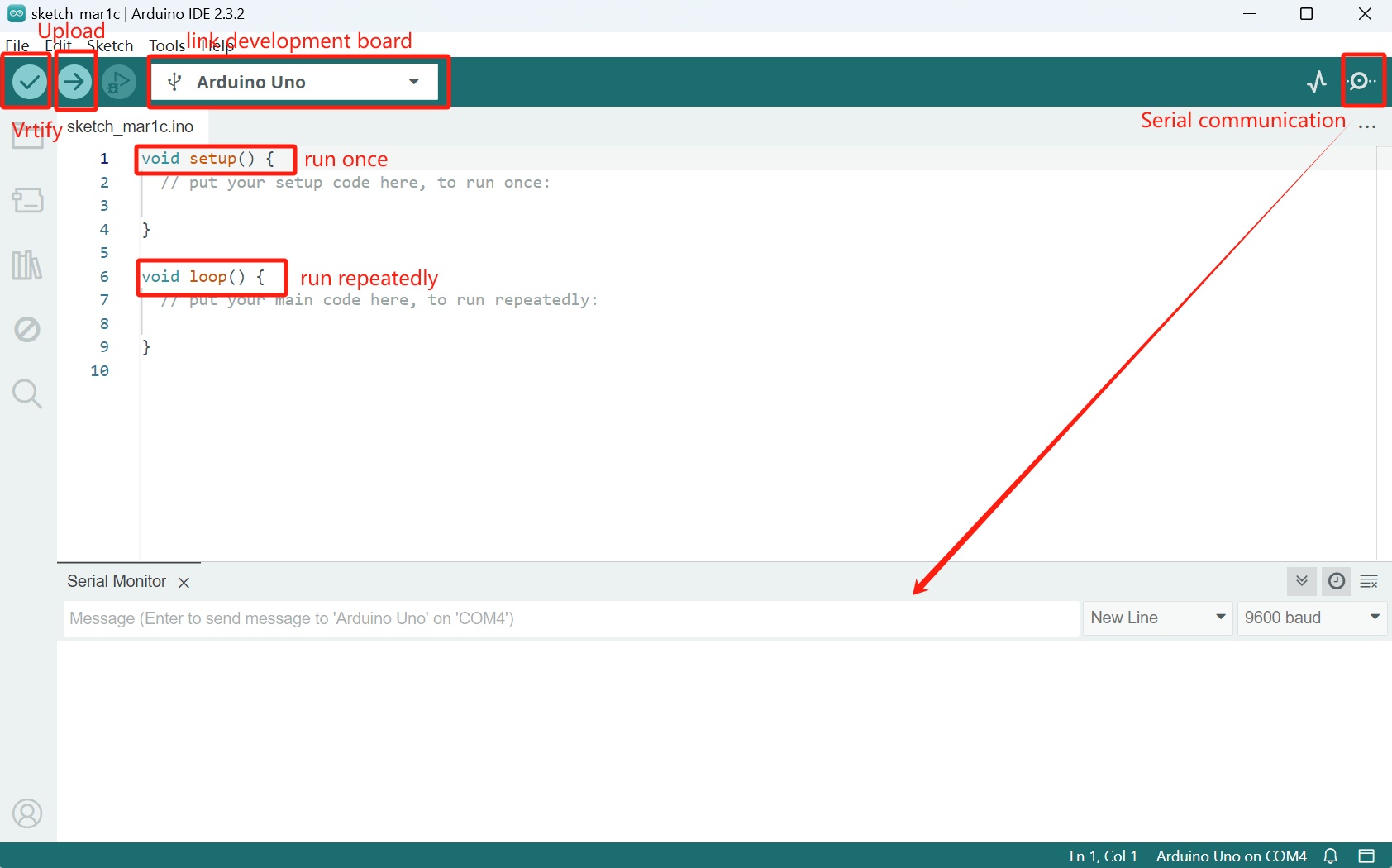
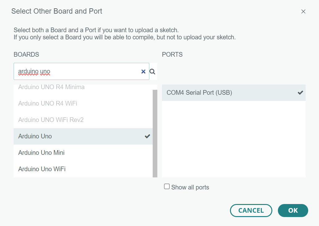
After installing, choose
Arduino Unoin the top selection box.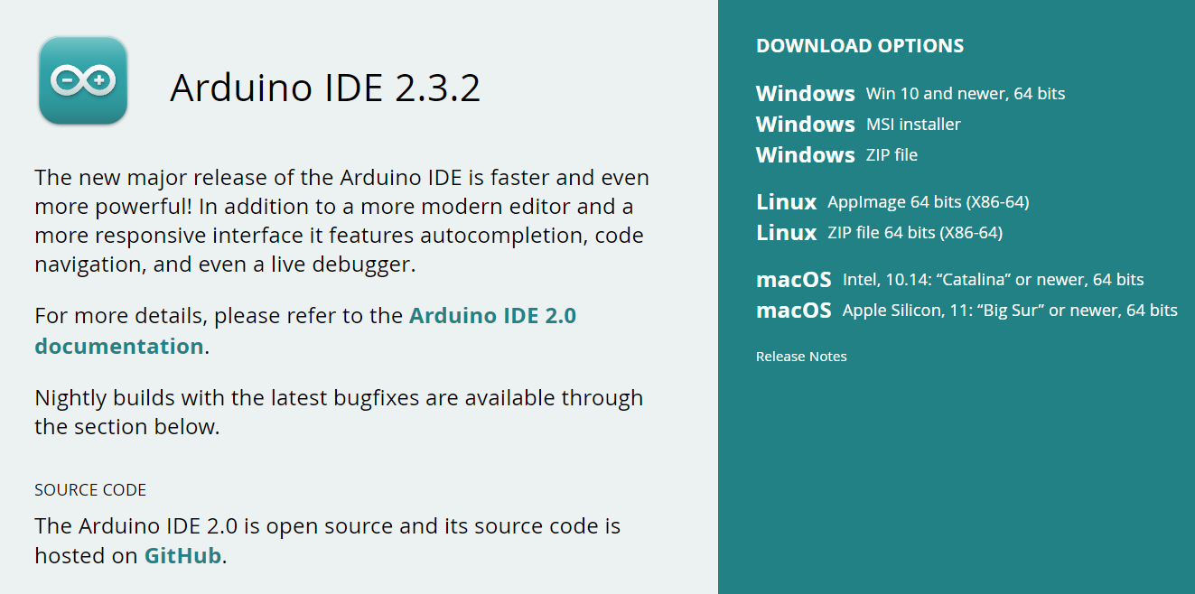
-
Write the code in the text editing area, (texts after
//are comments).int ledPin = 10; void setup() { // put your setup code here, to run once: pinMode(ledPin, OUTPUT); } void loop() { // put your main code here, to run repeatedly: digitalWrite(ledPin, HIGH); // turn the LED on (HIGH is the voltage level) delay(1000); // wait for a second digitalWrite(ledPin, LOW); // turn the LED off by making the voltage LOW delay(1000); // wait for a second } -
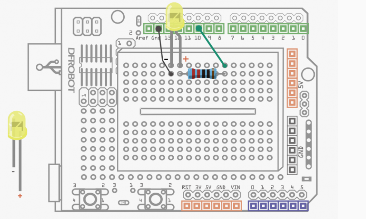
Hardware connection, Note: the two pins of the LED have different length, the longer one is
+, the shorter one is-.The connection is shown below (1 x DFduino UNO R3, with USB cable, 1 x Prototype Shiled + breadboard, 2 x cables, 1 x 5mm LED, 1 x 200Ohm resistor):
-
Look!
RP2040

The RP2040 is a microcontroller is designed by Raspberry Pi, product page and datasheet.
Basic specs
- Dual ARM Cortex-M0+ @ 133MHz
- 264kB on-chip SRAM in six independent banks
- Support for up to 16MB of off-chip Flash memory via dedicated QSPI bus
- DMA controller
- Fully-connected AHB crossbar
- Interpolator and integer divider peripherals
- On-chip programmable LDO to generate core voltage
- 2 on-chip PLLs to generate USB and core clocks
- 30 GPIO pins, 4 of which can be used as analogue inputs
- Peripherals
- 2 UARTs
- 2 SPI controllers
- 2 I2C controllers
- 16 PWM channels
- USB 1.1 controller and PHY, with host and device support
- 8 PIO state machines
Seeed Xiao RP2040
The RP2040 microcontroller can also be programmed by the Arduino platform. We are using the Seeed Studio Xiao RP2040 as the develpment board for RP2040, and Seeed Studio has official documentation for programm the Xiao RP2040 via Arduino IDE.
Follow the instruction and installed the Arduino core for RP2040 to Arduino IDE, we can write code for the RP2040 microcontroller using the same set of API to control the board.
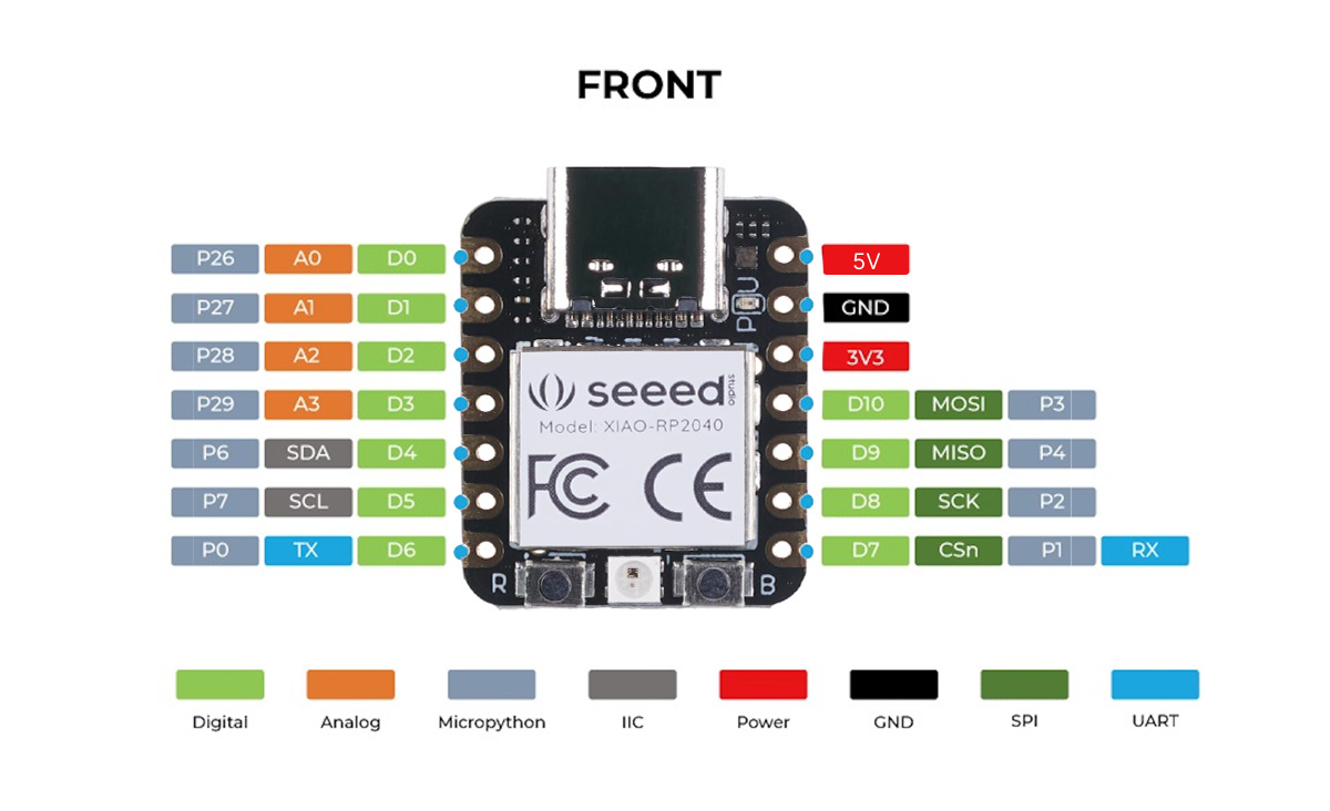
As the product page stated, the Xiao RP2040 has the following specs:
- Flash Memory: 2MB
- SRAM: 264KB
- Digital I/O Pins: 11
- Analog I/O Pins: 4
- PWM Pins: 11
- I2C interface: 1
- SPI interface: 1
- UART interface: 1
- Power and downloading interface: Type-C
- Power: 3.3V/5V DC
- Dimensions: 20×17.5×3.5mm
Due to its small formfactor, the Xiao RP2040 doesn't expose all the peripheral capabilities of the RP2040, and an error in the documentation led to some confusion when we were testing the board. (See Findings about the RP2040 Serial situation)
Seeed Studio Xiao RP2040 Schematic
ESP32
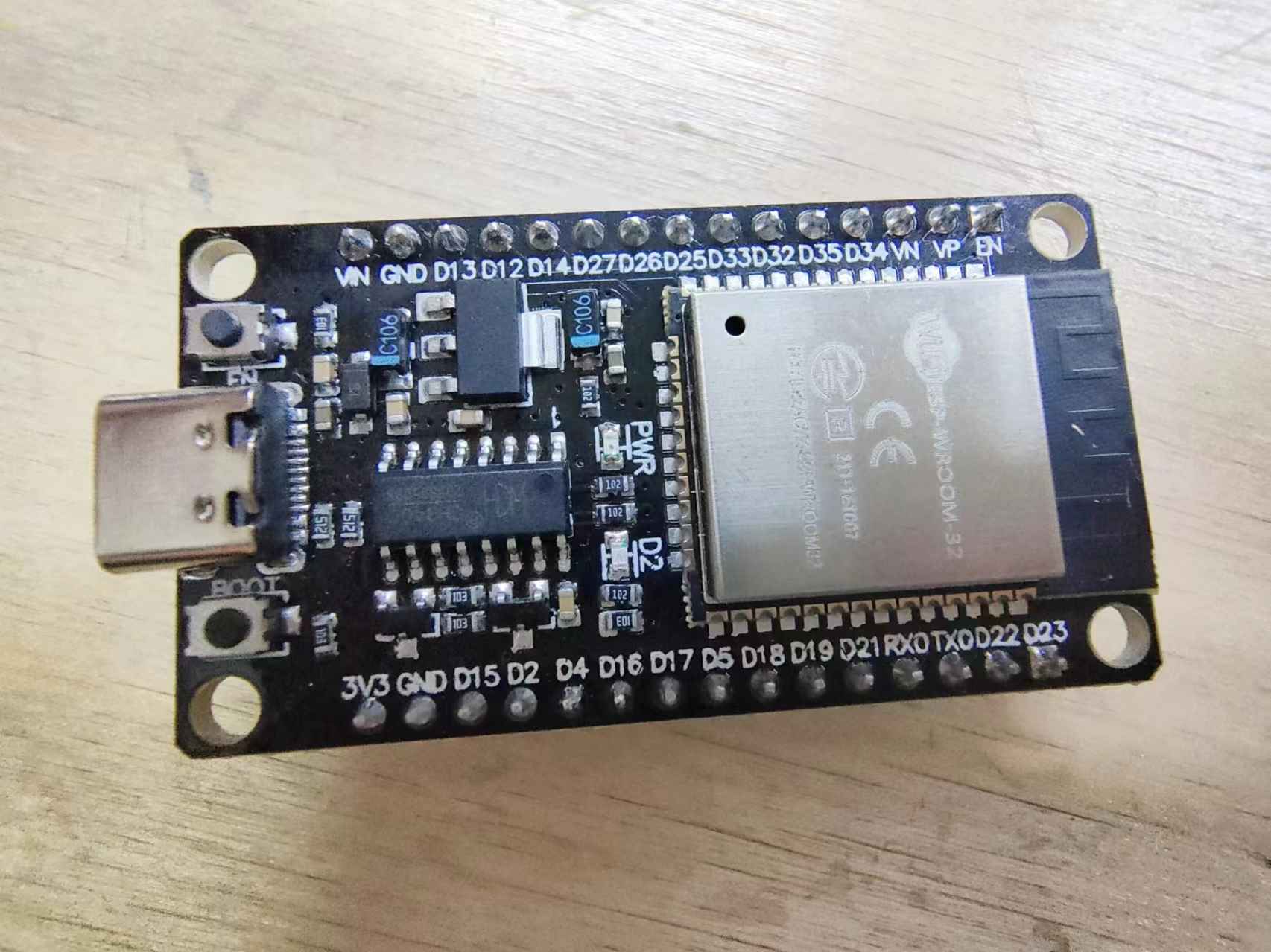
The development board we have for the ESP32 chip is similiar to the official ESP32-DevKitC dev board from Espressif but with a USB Type-C connector. It has a ESP32-WROOM-32 at its core.
Use Arduino IDE to program ESP32 Dev Board
The latest version of the Arduino IDE has ESP32 platform support directly, meaning we don't have to install some other board definition file to uset the ESP32 boards.
-
Open Arduino IDE, open the
Board Managerpane, search for "esp32", and install theesp32platform.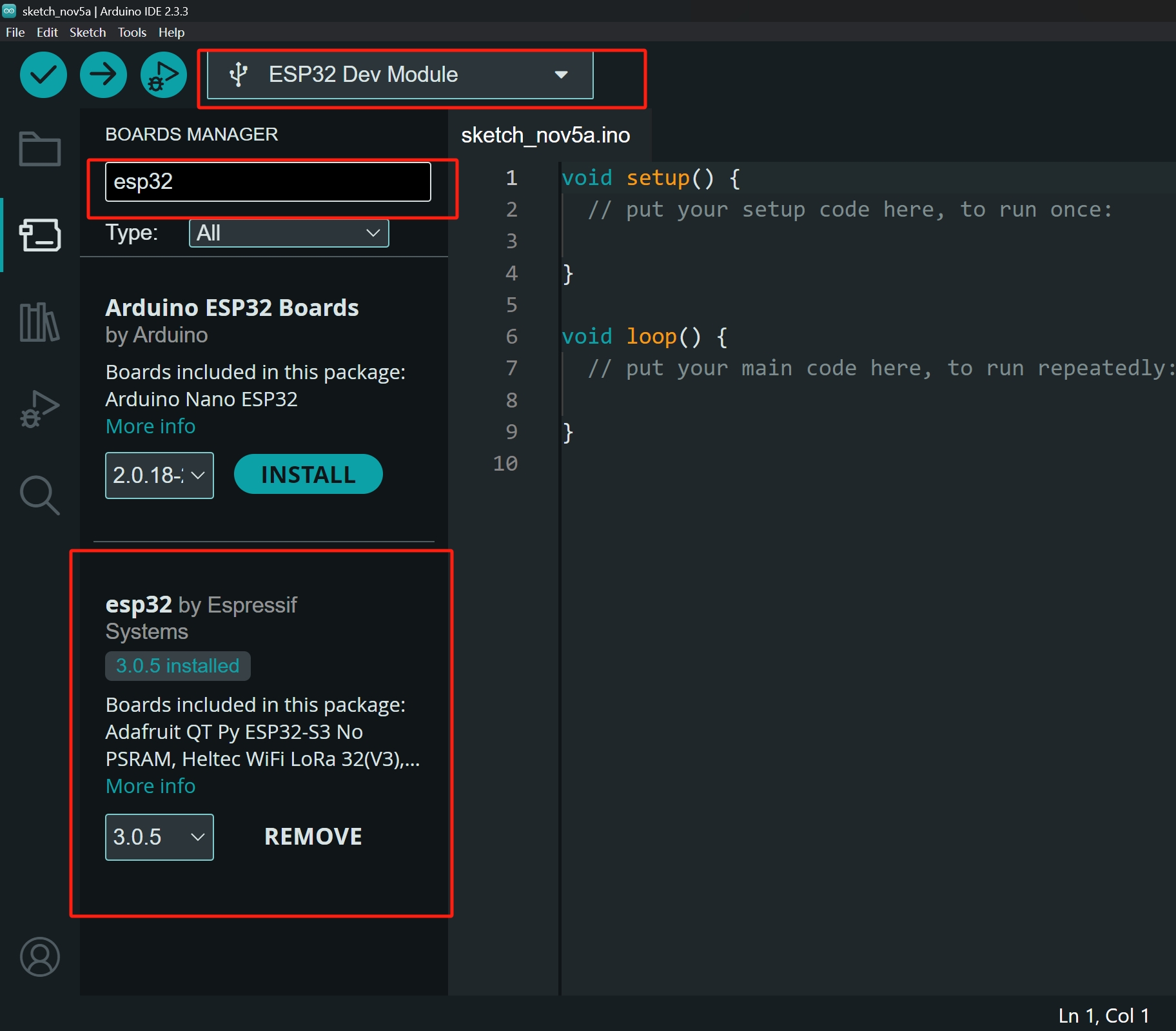
-
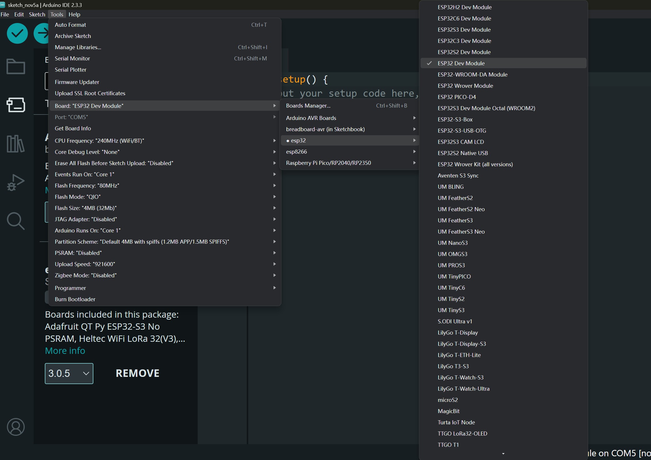
After installing the platform, in menu select:
Tools -> Board -> esp32 -> ESP32 Dev Module, then we can write code and upload to the ESP32 dev board.The API documentation for the ESP32 Arduino Core can be found here.
