WEEK 9
Output devices
Group Assignment:
- Measure the power consumption of an output device
Individual Assignment:
- Add an output device to a microcontroller board you've designed, and program it to do something
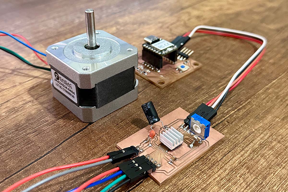
This week, I made a stepper motor controller board based on the DRV8428 driver. With this board, and the board I designed during the electronics production week, I tested a stepper motor and was able to observe its current consumption. I also learned to use some basic functions of the OLED display SSD1306. In the group part, we measured the current consumption of a stepper motor using another card.
Group Assignment
This week, I worked with Naldi to develop the group section. You can find our work here.
Individual Assignment
DRV8428 MOTOR DRIVER
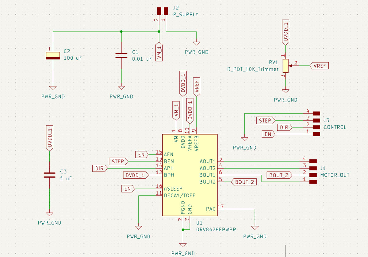
To made the driver, I attempted to replicate the example from the datasheet, which is a basic configuration for 1/8 microstepping. I had to replace the 0.47 uF capacitor with a 1 uF one because we currently don't have 0.47 uF capacitors in the lab. According to the datasheet, the capacitor I replaced can be in the range of 0.47 uF to 1 uF.
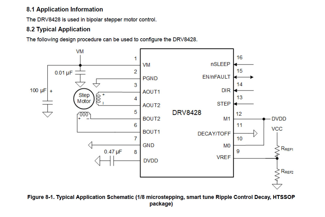
In the schematic design, I added connectors for the control that will be connected to the main board, a 4-pin connector for the motor inputs, and a two-pin connector for the motor power supply.
The DRV8428 driver is very small, so for this reason, I increased the width of the pads at the ends to make it easier to solder after, and also to prevent the tracks from lifting due they are too thin.
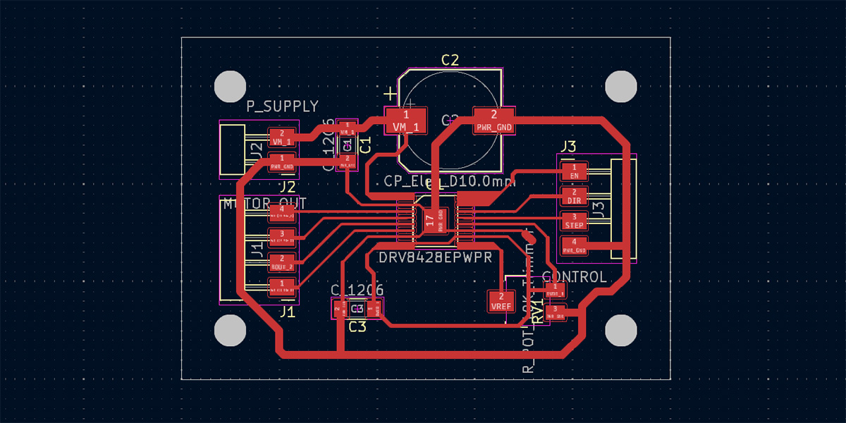
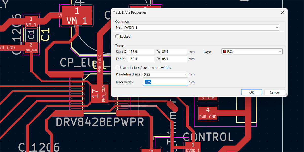
I also had to edit the footprint of the DRV8428 driver to use a 1/64” end mill. For this reason, I had to change the width of the pads to 0.25 mm, with this chamge I achieve a clearance of 0.40 mm between pads.
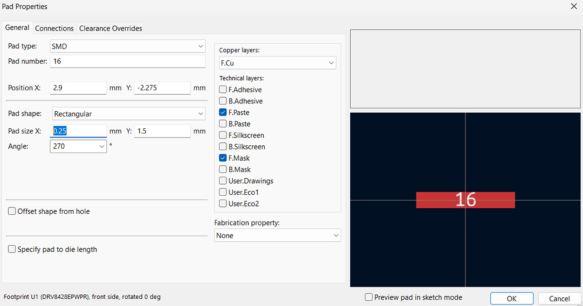
Due to the change in the pads, I also changed the width of the tracks to the same value of 0.25 mm. Since this is a very small value, there's a risk of the tracks breaking or lifting, so wherever possible, I increased the width to 0.4 mm.
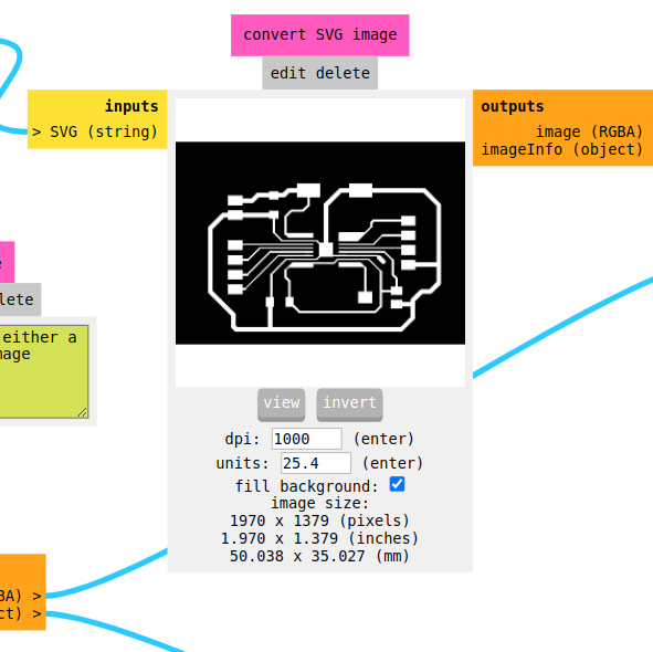
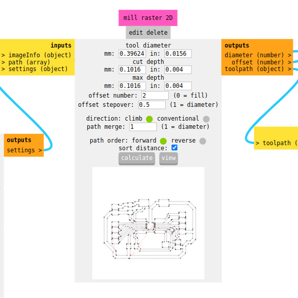
With the that considerations, I obtained the traces and the holes for the board. Then, I exported them in SVG format.
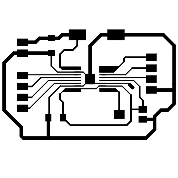
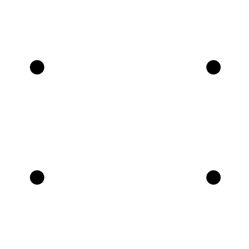
It was necessary to invert the image so that the background would be black and also set the DPI to 1000. I chose 1/64" mill for the tracks and 1/32" mill to cut the board edge.
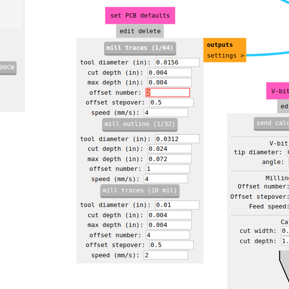
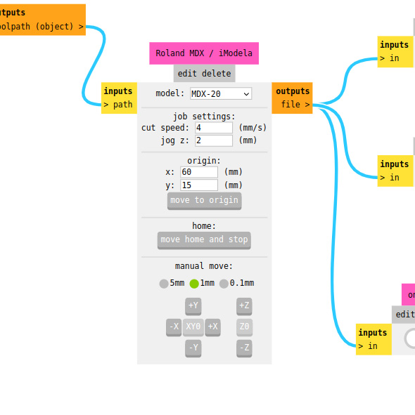
I calculated the toolpaths, repositioned the milling cutter at a new origin, I calibrated the Z-axis and proceed to send the cut.
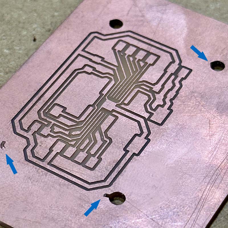
In the following images, you can see the milling of the board.
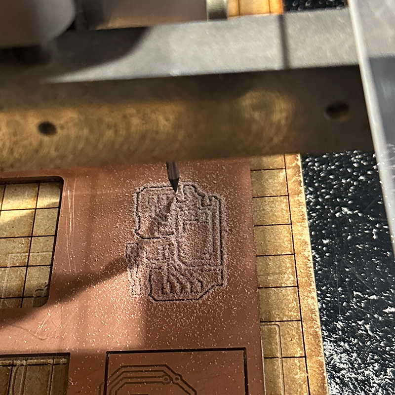
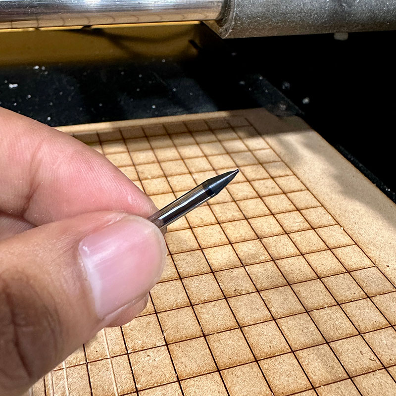
I tried to use the same procedure to make the holes, but it seems I didn't adjust the milling cutter properly, and unfortunately, the 1/32" cutter broke. It's also possible that while cutting the holes, the cutter got stuck with the leftover central part of the hole. For this reason, I had to mill the board again.
After the entire milling process, I proceeded to solder the components. In this case, I used some surface-mount components as well as the common ones. To solder the DRV8428, I used FLUX, which made it easier.
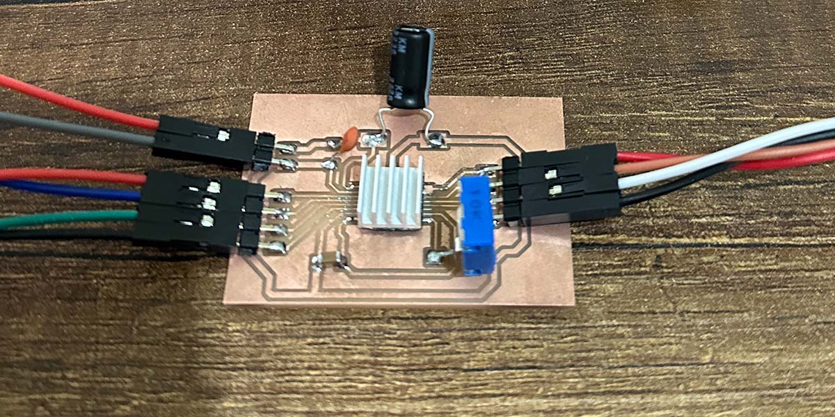
I used the board I made during the electronic production week to control the stepper motor. From this board, the STEP and DIRECTION signals are emitted, and also 3.3 V for the ENABLE of the controller. I also used a variable power supply that was set to 12V and 1A of current.
I used the following Arduino program to test the motor's operation. The program is quite simple; it rotates the motor one turn and then another turn in the opposite direction.
#define DIR 3
#define STEP 4
#define NSTEPS 1600
#define DELAYHIGH 2000
#define DELAYLOW 2000

void setup() {
pinMode(STEP,OUTPUT);
digitalWrite(STEP,LOW);
pinMode(DIR,OUTPUT);
digitalWrite(DIR,LOW);
}

void loop() {
digitalWrite(DIR,HIGH);
for (int i = 0; i < NSTEPS; ++i) {
digitalWrite(STEP,HIGH);
delayMicroseconds(DELAYHIGH);
digitalWrite(STEP,LOW);
delayMicroseconds(DELAYLOW);
}
digitalWrite(DIR,LOW);
for (int i = 0; i < NSTEPS; ++i) {
digitalWrite(STEP,HIGH);
delayMicroseconds(DELAYHIGH);
digitalWrite(STEP,LOW);
delayMicroseconds(DELAYLOW);
}
}
In the following video, you can see the operation of the stepper motor. We can also observe that the current consumption is approximately 200 mA with 12 V.
SSD1306 dISPLAY
This week, I also tested this small SSD1306 display, which uses the I2C protocol to communicate with the controller.
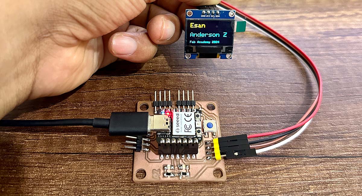
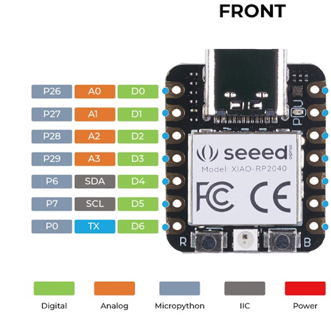
The communication with the I2C protocol uses only 4 pins: one forground (GND), one for power (VCC) , a clock line (SCL), and a data line (SDA). The Xiao RP 2040 microcontroller and the display have these pins and are connected directly.
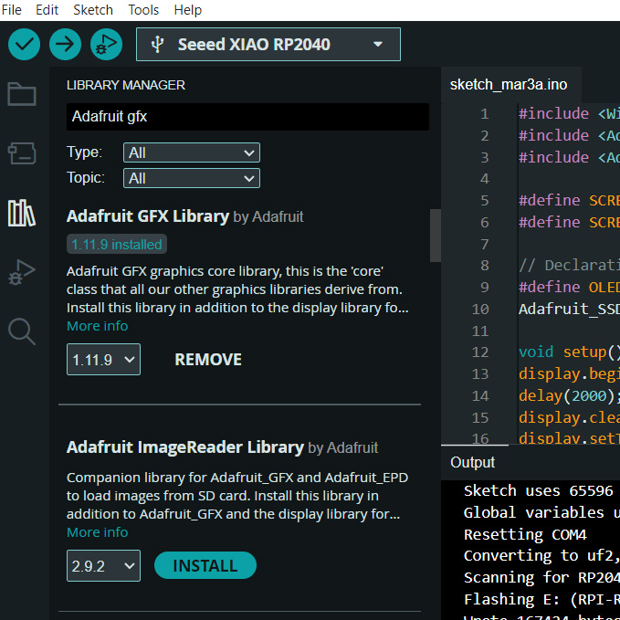
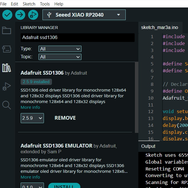
The first thing I did was to add the Adafruit GFX and Adafruit SSD1306 libraries from the library manager.
I also used the following Arduino code to test the display, which is a modified version of Picaio's work where they use an ultrasonic sensor to measure and display distances on the display.
#include <Wire.h>
#include <Adafruit_GFX.h>
#include <Adafruit_SSD1306.h>
#define SCREEN_WIDTH 128 // OLED display width, in pixels
#define SCREEN_HEIGHT 64 // OLED display height, in pixels
// Declaration for an SSD1306 display connected to I2C (SDA, SCL pins)
#define OLED_RESET -1 // Reset pin # (or -1 if sharing Arduino reset pin)
Adafruit_SSD1306 display(SCREEN_WIDTH, SCREEN_HEIGHT, &Wire, OLED_RESET);
void setup() {
display.begin(SSD1306_SWITCHCAPVCC, 0x3C);
delay(2000);
display.clearDisplay();
display.setTextColor(WHITE);
}
void loop() {
display.clearDisplay();
// display R G B Values
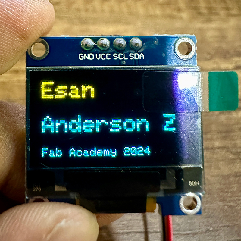
display.setTextSize(2);
display.setCursor(0,0);
display.print("Esan");
display.setTextSize(2);
display.setCursor(0, 28);
display.print("Anderson Z");
display.setTextSize(1);
display.setCursor(0, 56);
display.print("Fab Academy 2024");
display.display();
delay(500);
}
Download:
Here you can download de files of milling in SVG format:
References:
- Stepper motor board by JVA
- Oled display example of Picaio
- Wiki seeedstudio