WEEK 7
Computer-controlled machining
Group Assignment:
- Do your lab's safety training
- test runout, alignment, fixturing, speeds, feeds, materials and toolpaths for your machine
Individual Assignment:
- Make (design+mill+assemble) something big (~meter-scale)
- Extra credit: Don't use fasteners or glue
- extra credit: Include curved surfaces
This week, I learned to use the CNC milling machine that we have in the lab. It was a week I enjoyed a lot because I felt there was a lot of work to be done, like conducting tests, designing the tests, designing a piece of furniture, cutting, and assembling.
Group Assignment
This week, I worked with Naldi to develop the group section. You can find our work here.
Individual Assignment
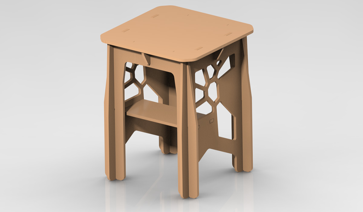
For the individual part of the week, I designed a piece of furniture similar to a table or desk that will be used to place my 3D printer on. The first thing I did was search for some references of furniture made with a CNC milling machine to gather some ideas. I also took measurements of my printer to determine the size of the table. The following image shows the final design rendered in Creo.
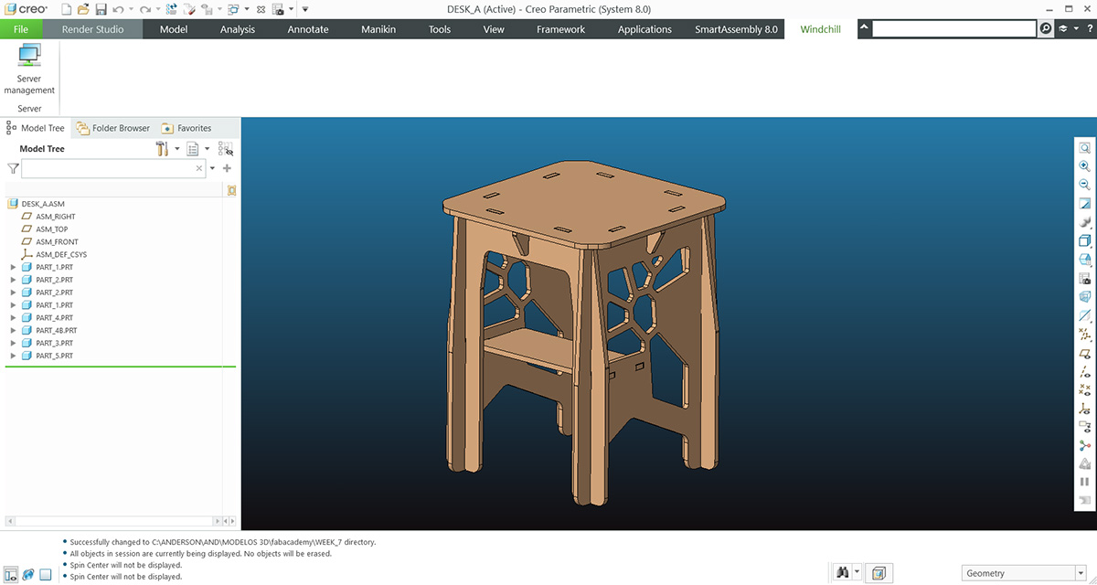
I used Creo to design the parts and the overall assembly, as well as to create the drawing which I then exported in DXF format that can be read by Vcarve Pro 7, which is the program I used to generate the G-codes of the cuts.
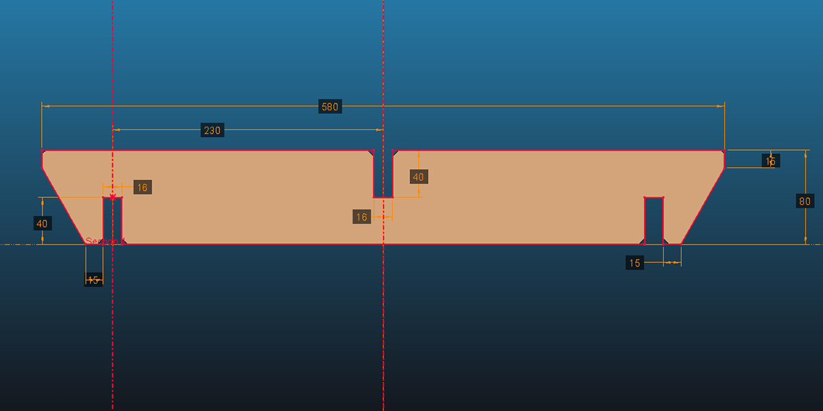
Some special considerations that should be kept in mind for the design are the following.
- In the joints, was used a tolerance of 1mm, which was determined through testing to achieve a proper fit. Therefore, since the MDF material is 15mm thick, the slots were designed to be 16mm wide.
- Chamfers should be added to all the slots to facilitate assembly.
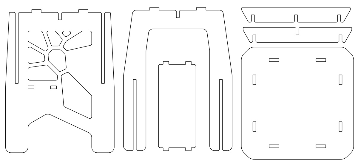
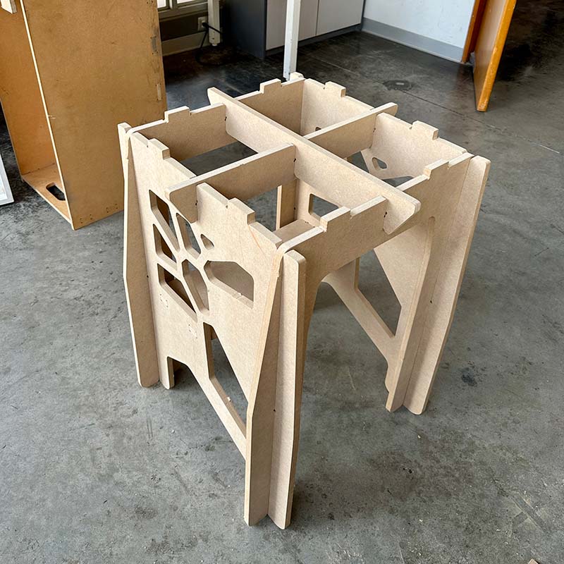
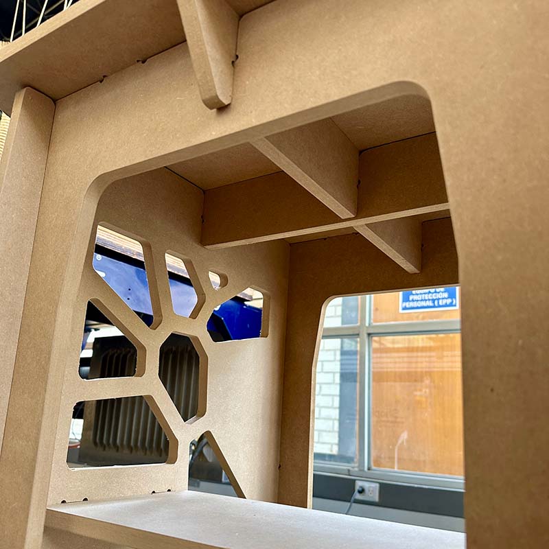
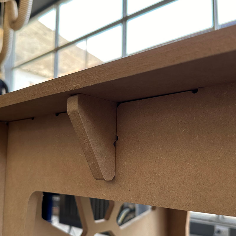
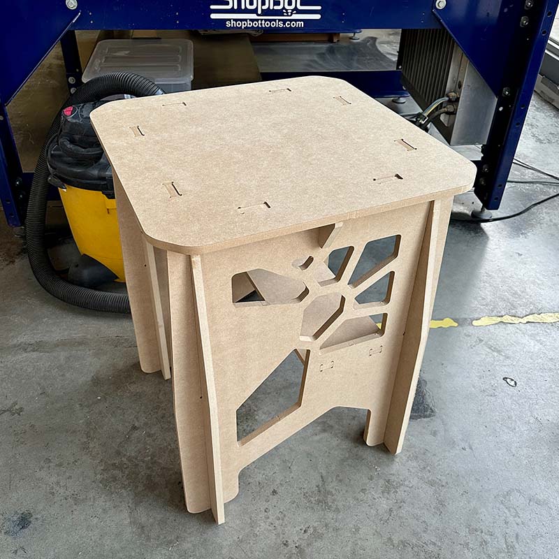
The table I designed consists of eight pieces, as shown in the following image. The legs need to be cut twice. To avoid it being a flat panel, I made some cuts in the side panels and also added a small surface to support some items and to provide greater stability to the structure. After creating the drawings of the parts, I exported them in DXF format, version 2010, since this is the format recognized by Vcarve.
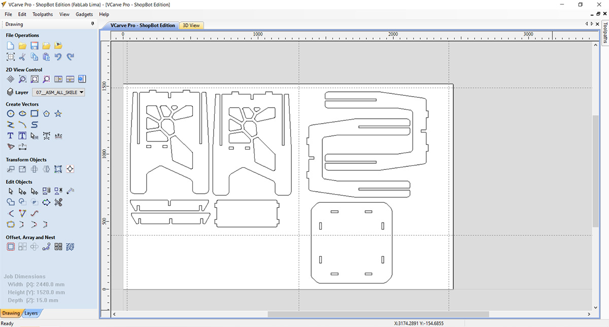
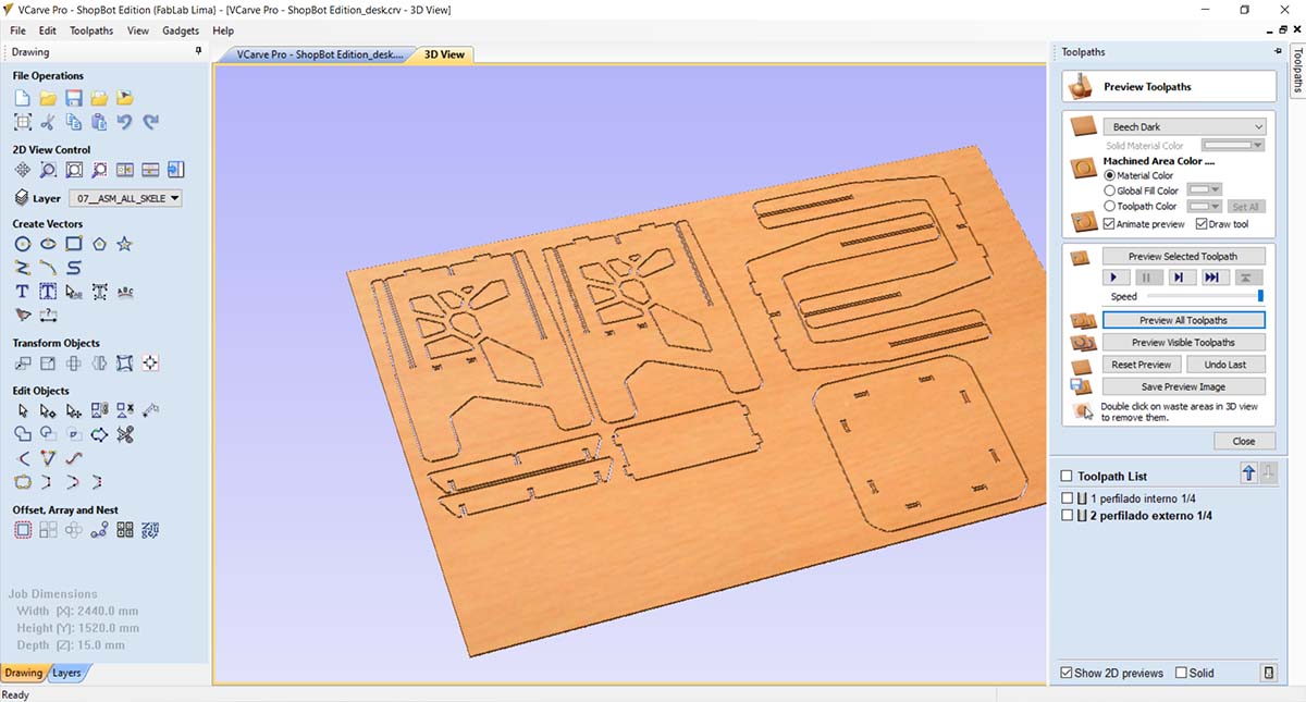
The software I used to perform the cuts, simulation, time calculation, and obtaining the G-codes was Vcarve Pro 7. I opened a new project and imported the DXF file of my design. Then, I duplicated the necessary parts and arranged them so they would fit within the CNC milling machine's work area. Before this, I defined an area with the help of the rulers in the bottom left, which is where I cut the pieces for the group part tests since I used the same MDF board.
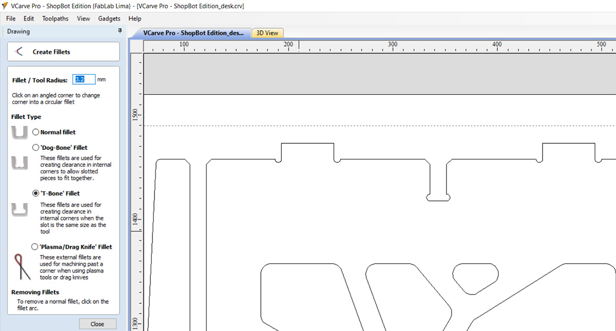
After placing all the elements, I added fillets to the design at all the joints. The fillets were added to ensure that all the pieces can be assembled correctly. Vcarve has a very user-friendly tool that allows you to choose from various types. In this case, I used the T-bone type. Since I had to use a ¼ inch mill, the radius for the fillets was set to 3.2 mm.
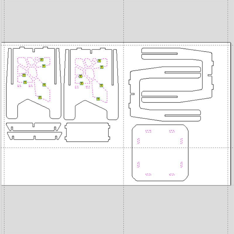
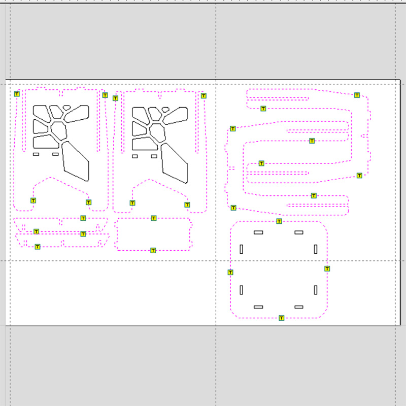
Then I started with the simulation of the cuts. For this table, only two types of machining were necessary: an internal cut for the decorative pattern on the side panels and for the assembly slots; and an external cut for the outlines. It was also necessary to add pads, which serve to prevent the piece from moving while cutting. In the internal cut, it was only necessary to add pads to the larger parts.
Both cuts were made with a ¼ inch mill, so it wasn't necessary to change the tool.
After running the simulation of the cuts, I exported the trajectories in SBP format, which is used by the CNC cutter.
To start the cutting process, follow these steps:
- The first thing I did was to install/change the mill. In this case, I'll be using the ¼ inch mill for all the cuts.
- Then, turn on the machine and press the RESET button.
- Next, open the program. The software that controls the CNC milling machine is called Shopbot 3.
- Proceed with the Z-axis calibration
- Proceed with the XY-axis calibration
- Turn on the dust collector
- Load the SBP files, and start.
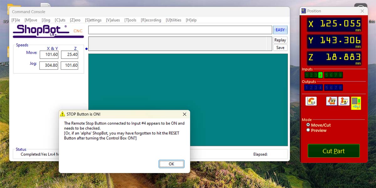
It's important to press the RESET button before starting the program. If we don't do this, we will get the following message upon starting:
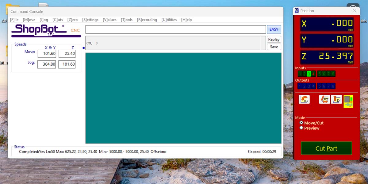
The software that controls the CNC has shortcuts for performing calibrations and for moving the head.
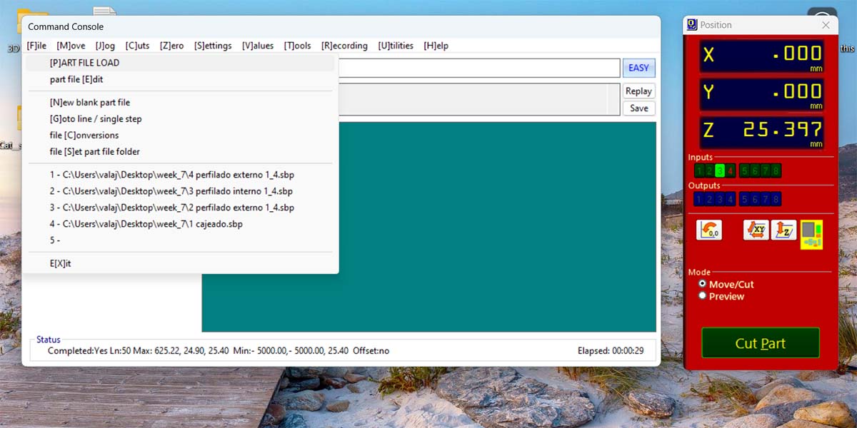
To load the cutting files, you should go to File > [P]ART FILE LOAD and select the SBP that corresponds to the cut you want to make.
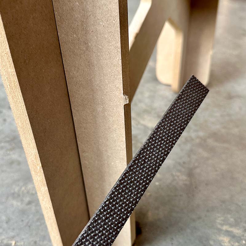
Make both internal and external cuts took about 30 minutes. After the machine finished, I removed the remaining dust with a vacuum cleaner, and then I removed the parts using a rubber hammer and a chisel to cut the pads. Next, I sanded the edges of the pieces with sandpaper and proceeded with the assembly.
I also needed to use a file to remove the pads. I noticed that in some parts, the assemblies didn't fit completely, so I also filed the edges of the slots a bit to improve the fit.
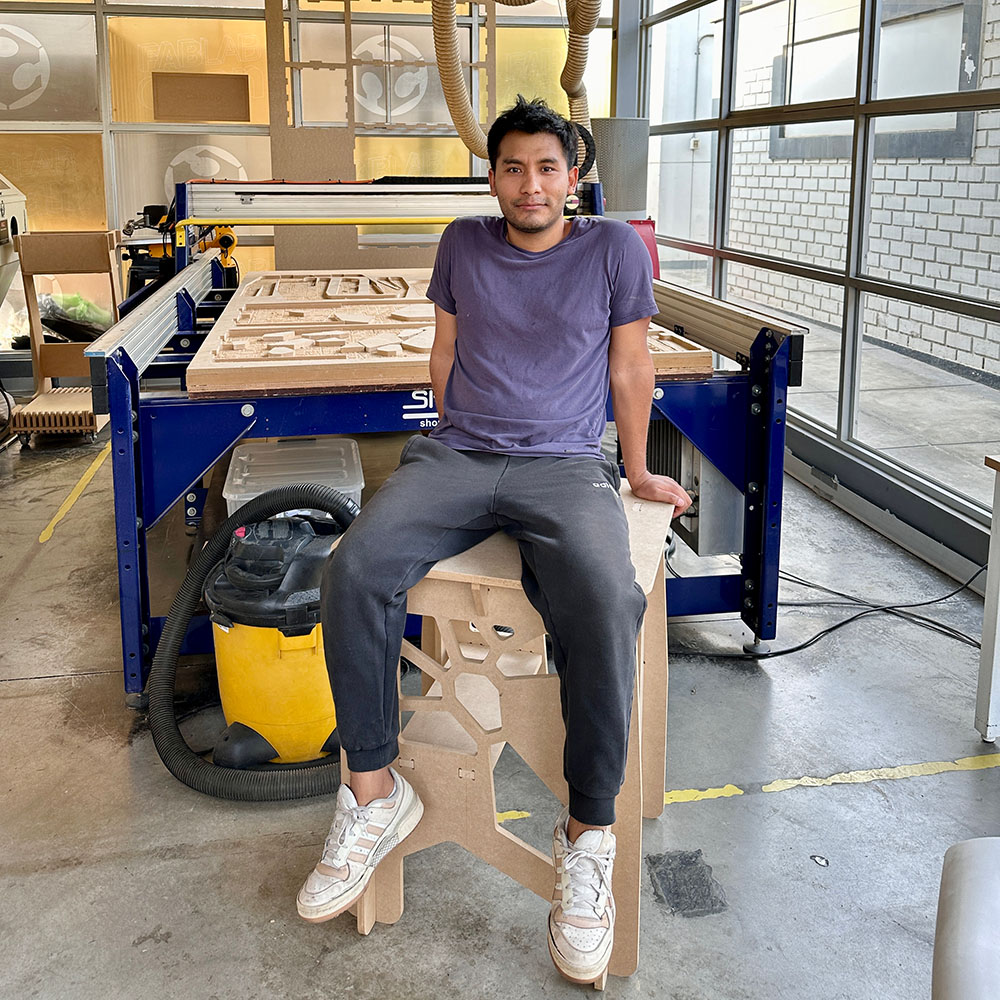
I really liked the final result; it's a very stable table, and I also really like the design.
Download:
Here you can download de files of the desk/table: